1988 PONTIAC FIERO ignition
[x] Cancel search: ignitionPage 1322 of 1825
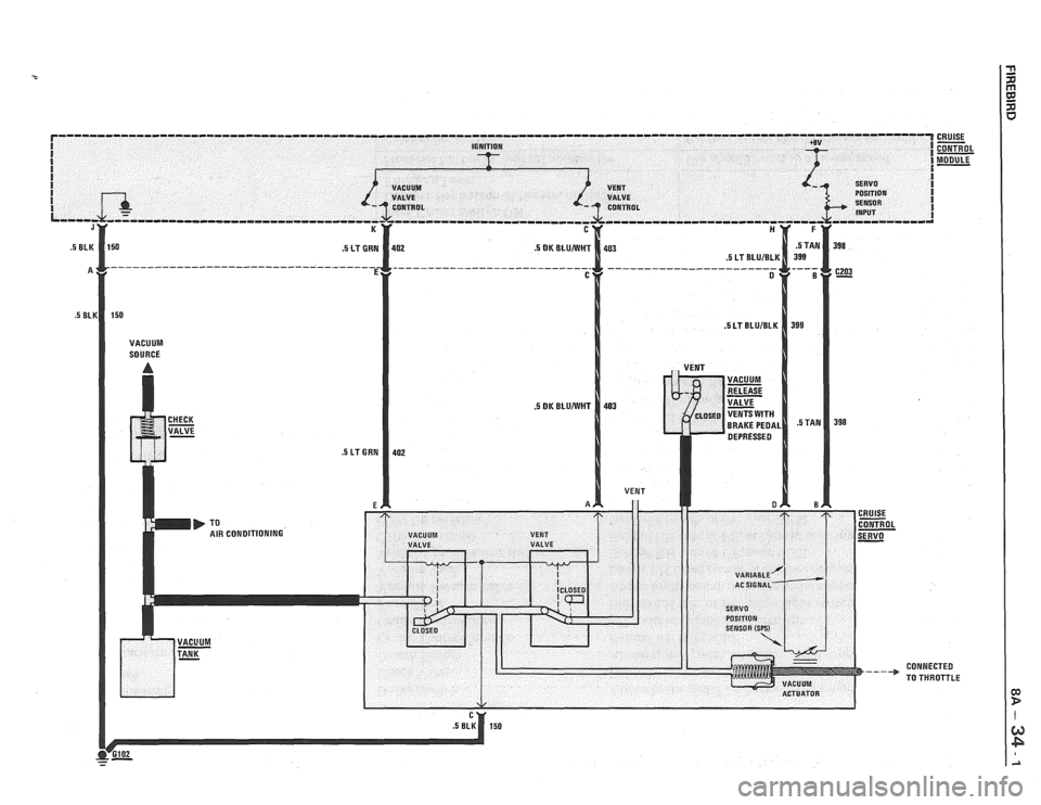
r--------------------------------------------------------------------------------------------------------------- I I IGNITION
I I I I SERVO I VACUUM I
I POSITION I
I SENSOR I INPUT I
CONNECTED
TO THROTTLE
Page 1324 of 1825
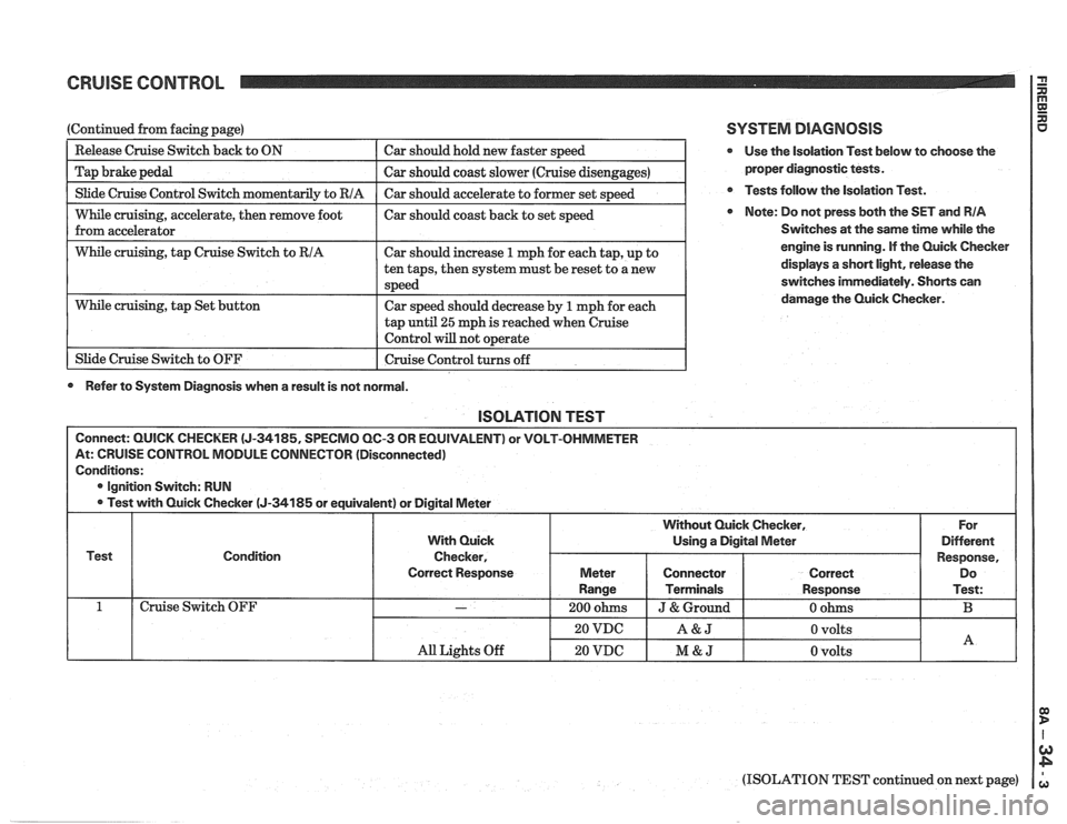
CRUISE CONTROL 2
I Slide Cruise Control Switch momentaril~ to RIA I Car should accelerate to former set s~eed I
(Continued from facing page)
--
While cruising, accelerate, then remove foot I car should coast back to set speed
from accelerator
Release Cruise Switch
back to ON
Tap brake pedal
I While cruising, tap Cruise Switch to RIA I Car should increase 1 mph for each tap, up to I
Car should hold new faster speed
Car should coast slower (Cruise disengages)
tap
until 25 mph is reached when cruise
Control will not o~erate I
While cruising, tap Set button
1 Slide Cruise Switch to OFF ten
taps, then system must be reset to a new
speed
Car speed should decrease by
1 mph for each
I Cruise Control turns off 1
0 Refer to System Diagnosis when a result is not normal.
SYSTEM DIAGNOSIS
@ Use the isolation Test below to choose the
proper diagnostic tests.
@ Tests follow the Isolation Test.
Note: Do not press both the SET and RIA
Switches at the same time while the
engine is running. If the Quick Checker
displays
a short light, release the
switches immediately. Shorts can
damage the Quick Checker.
lSOLATlON TEST
Connect: QUICK CHECKER (J-34185, SPECMO QC-3 OR EQUIVALENT) or VOLT-OHMMETER
At: CRUISE CONTROL MODULE CONNECTOR (Disconnected)
Conditions:
@ Ignition Switch: RUN
Test with Quick Checker
(J-34185 or equivalent) or Digital Meter
Test Condition
Cruise Switch OFF
(ISOLATION TEST continued on next page)
All Lights Off
With Quick
Checker,
Correct Response
-
20 VDC
20 VDC
For
Different
Response, Do
Test:
B
Without Quick Checker,
Using a Digital Meter
A&J
M&J
Meter
Range
200 ohms
0 volts
0 volts
Connector
Terminals
J & Ground
A
Correct
Response
0 ohms
Page 1325 of 1825
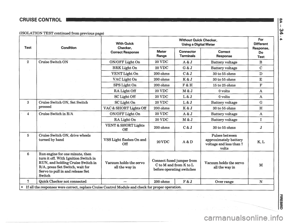
CRUISE CONTROL
(ISOLATION
Test
2 3
4
5
6
7
If all
TEST continued from previous page)
Condition
Cruise Switch ON
Cruise Switch ON, Set Switch
pressed
Cruise Switch
in RIA
Cruise Switch ON, drive wheels
turned by hand
Run engine for one minute, then
turn it off. With Ignition Switch in
RUN, and holding Cruise Switch
in
RIA, press Set Switch, wait for
Servo to pull
in and release Set
Switch
Quick Checker not connected
the responses were correct, replace Cruise
With Quick
Checker,
Correct Response
ONIOFF Light On
BRK Light On
VENT Light On
VAC Light On
SPS Light On
RA Light Off
SC Light Off
SC Light On
VAC
& SNORT Lights Off
ONIOFF Light On
RA Light On
VENT & SNORT Lights
Off
VSS Light flashes On and
Off
Vacuum holds the servo
all theway in
-
Control Module and check
Without Quick Checker, For
Using
a Digital Meter Different
Meter
Range
20 VDG
20 VDC
200 ohms
200 ohms
200 ohms
20 VDC
20 VDC
20 VDC
200 ohms
20 VDC
20 VDC
200 ohms
20VDC
Connector Terminals
A&J
G&J
C&J
K&J
F&N
M&J
L&J
L&J
K&J
A&J
M&J
C&J
A&D
Response,
Correct Do
Response Test
Battery voltage B
Battery voltage C
30 to 55 ohms D
30 to 55 ohms E
15 to 25 ohms F
0 volts A
0 volts
A
Battery voltage G
30 to 55 ohms N
Battery voltage A
Battery voltage
I
30 to 55 ohms J
Pulses between
approximately battery
voltage and less than
7 K, L
volts
Connect fused jumper from
CtoMandfromKtoL
before operating switches
200ohms 1 F&J
for proper operation.
Vacuum holds the servo
all the way in M
Over range N
Page 1326 of 1825
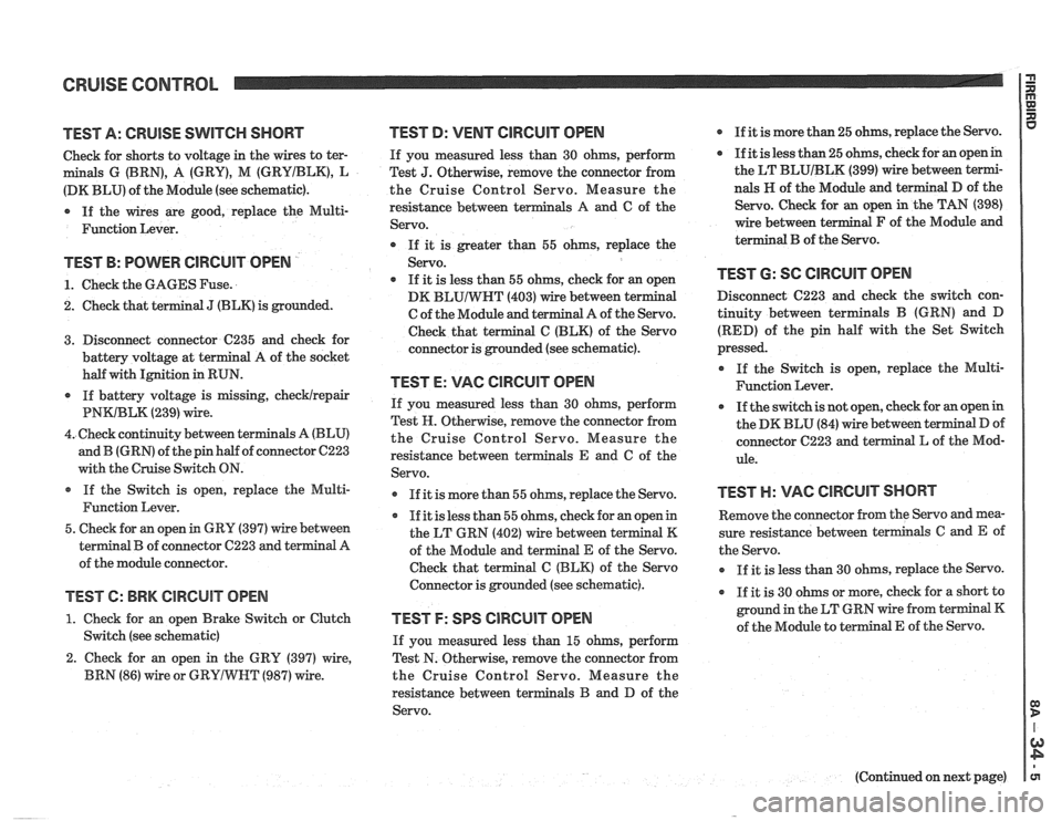
CRUISE CONTROL 13 rn E
TEST A: CRUISE SWITCH SHORT
Check for shorts to voltage in the wires to ter-
m als G (BRN), A (GRY), M (GRYIBLK), L
(DK BLU) of the Module (see schematic).
* If the wires are good, replace the Multi-
Function Lever.
TEST B: POWER ClRCUlT OPEN
1. Check the GAGES Fuse.
2. Check that terminal
J (BLK) is grounded.
3. Disconnect connector
C235 and check for
battery voltage at terminal A of the socket
half with Ignition
in RUN.
* If battery voltage is missing, checklrepair
PNWBLK (239) wire.
4. Check continuity between t
and B (GRN) of the pin half of connector C223
with the Cruise Switch ON.
If the Switch is open, replace the Multi-
Function Lever.
5. Check for an open in GRY (397) wire between
al
B of connector C223 and terminal A
of the module connector.
TEST 6: BRK CIRCUIT OPEN
1. Check for an open Brake Switch or Clutch
Switch (see schematic)
2. Check for an open in the
GRY (397) wire,
BRN
(86) wire or GRYIWNT (987) wire.
TEST D: VENT ClRCUlT OPEN
If you measured less than 30 ohms, perform
Test
J. Otherwise, remove the connector from
the Cruise Control Servo. Measure the
resistance between
terminals A and C of the
Servo.
If
it is greater than 55 ohms, replace the
Servo.
* If it is less than 55 ohms, check for an open
DK
BLUIWHT (403) wire between te
C of the Module and
t
Check that terminal C (BLK) of the Servo
connector is grounded (see schematic).
TEST E: VAC ClRCUlT OPEN
If you measured less than 30 ohms, perform
Test
IF. Otherwise, remove the connector from
the Cruise Control Servo. Measure the
resistance between
t als E and C of the
Servo.
If it is more than 55 ohms, replace the Servo.
If it is less than 55 ohms, check for an open in
the LT GRN (402) wire between t
of the Module and terminal E of the Servo.
Check that terminal C (BLK) of the Servo
Connector is grounded (see schematic).
TEST F: SPS CIRCUIT OPEN
If you measured less than 15 ohms, perform
Test N. Otherwise, remove the connector from
the Cruise Control Servo. Measure the
resistance between terminals
B and D of the
Servo.
r If it is more than 25 ohms, replace the Servo.
* If it is less than 25 ohms, check for an open in
the LT
BLUIBLK (399) wire between termi-
nals
H of the Module and
Servo. Check for an open
wire between
t al F of the Module and
terminal B of the Servo.
TEST 6: SC ClRGUlT OPEN
Disconnect C223 and check the switch con-
tinuity between terminals B (GRN) and D
(RED) of the pin half with the Set Switch
pressed.
* If the Switch is open, replace the Multi-
Function Lever.
If the switch is not open, check for an open in
the DK BLU (84) wire between terminal
D of
connector C223 and te al
L of the
Mod-
ule.
TEST H: VAC CIRCUIT SHORT
Remove the connector from the Servo and mea-
sure resistance between terminals
C and E of
the Servo.
r If it is less than 30 ohms, replace the Servo.
If it is 30 ohms or more, check for a short to
ground in the LT GRN wire from terminal K
of the Module to terminal
E of the Servo.
(Continued on next page)
Page 1334 of 1825
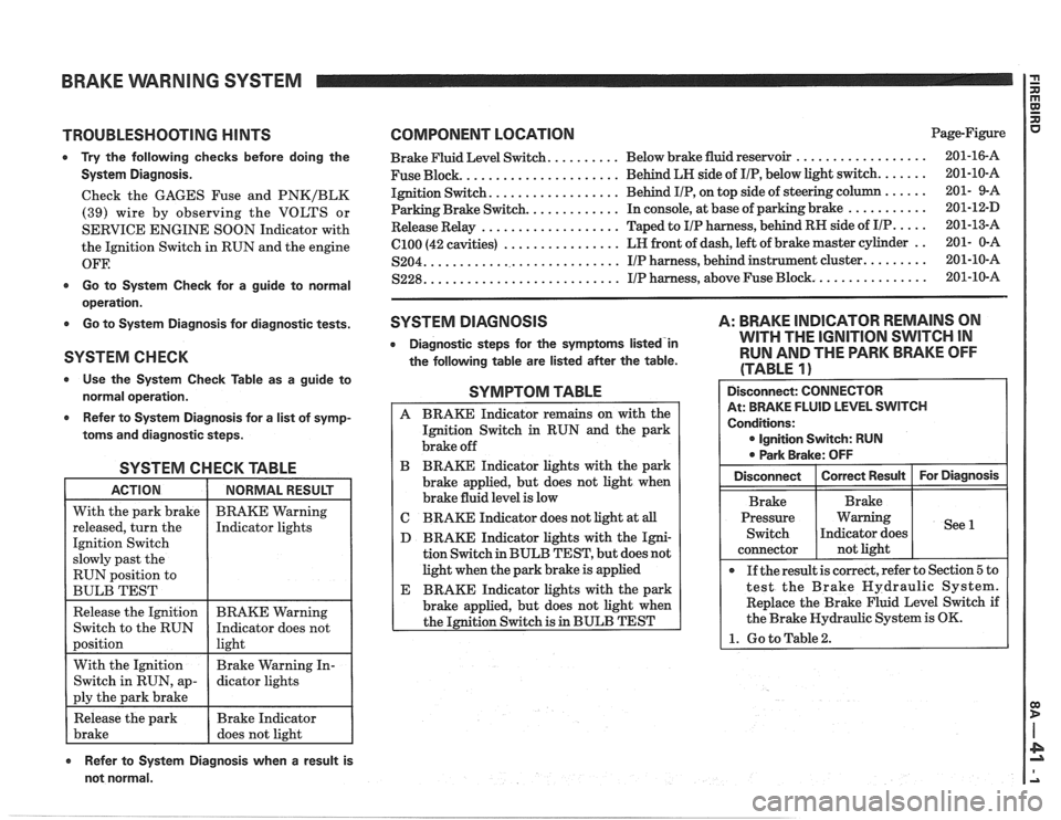
BRAKE VVARNlNG SYSTEM
TROUBLESHOOTING HINTS
0 Try the following checks before doing the
System Diagnosis.
Check the GAGES Fuse and PNKIBLK
(39) wire by observing the VOLTS or
SERVICE ENGINE SOON Indicator with
the Ignition Switch in RUN and the engine
OFF.
0 Go to System Check for a guide to normal
operation.
0 Go to System Diagnosis for diagnostic tests.
SYSTEM CHECK
Use the System Check Table as a guide to
normal operation.
e Refer to System Diagnosis for a list of symp-
toms and diagnostic steps.
SYSTEM CHECK TABLE
RUN position to
BULB TEST
COMPONENT LOCATION Page-Figure
.................. Brake Fluid Level Switch. ......... Below brake fluid reservoir 201-16-A
..................... Fuse Block. Behind
LH side of IIP, below light switch. ...... 201-10-A
................. Ignition Switch. Behind IIP, on
top side of steering column ...... 201- 9-A
Parking Brake Switch.
............ In console, at base of parking brake ........... 201-12-D
................... Release Relay Taped
to IIP harness, behind RH side of IIP. .... 201-13-A
................ (2100 (42 cavities) LR
front of dash, left of brake master cylinder .. 201- 0-A
........................... S204. IIP harness, behind instrument cluster. ........ 201-10-A
.......................... ............... S228. IIP harness, above Fuse Block. 201-10-A
SYSTEM DIAGNOSIS
0 Diagnostic steps for the symptorns listed'in
the following table are listed after the table.
A: BRAKE INDICATOR REMAINS ON
WITH THE
IGNITION SWITCH IN
RUN AND THE PARK BRAKE OFF
(TABLE
1)
SYMPTOM TABLE
A BRAKE Indicator remains on with the
Ignition Switch
in RUN and the park
brake off
B BRAKE Indicator lights with the park
brake applied, but does not light when
brake fluid level is low
C BRAKE Indicator does not light at all
D BRAKE Indicator lights with the Igni-
tion Switch in BULB TEST, but does not
light when the park brake is applied
E BRAKE Indicator lights with the park
brake applied, but does not light when
the Ignition Switch is in BULB TEST
Refer to System Diagnosis when a result is
not normal. Disconnect:
CONNECTOR
At: BRAKE FLUID LEVEL SWITCH
Conditions:
0 Ignition Switch: RUN
0 Park Brake: OFF
Pressure Warning
If the result is correct, refer to Section
5 to
test the Brake Hydraulic System.
Replace the Brake Fluid Level Switch if
the Brake Hydraulic System is OK.
1. Go to Table2.
Page 1335 of 1825
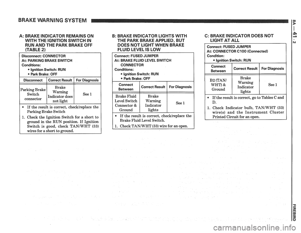
BRAKE WARNING SYSTEM I:
A: BRAKE INDICATOR REMAlNS ON
WITH THE lGNlTlON SWITCH IN
RUN AND THE PARK BRAKE OFF
(TABLE
2)
Disconnect: CONNECTOR I
At: PARKING BRAKE SWITCH
Conditions:
0 lgnition Switch: RUN
0 Park Brake: OFF
Disconnect
I Correct Result I For Diagnosis
Parking Brake
connector not light
If the result is correct, checklreplace the
Parking Brake Switch
1. Check the Ignition Switch for a short to
ground in the RUN position. If Ignition
Switch is good, check TANIWHT
(33)
wires for a short to mound.
B: BRAKE INDICATOR LIGHTS WITH 6: BRAKE INDICATOR DOES NOT
THE PARK BRAKE APPLIED, BUT
LIGHT AT ALL
DOES NOT
LIGHT WHEN BRAKE
FLUID LEVEL IS LOW
1. Check Indicator bulb, TANIWHT (33)
Connect: FUSED JUMPER
At: BRAKE FLUID LEVEL SWITCH
CONNECTOR
Conditions:
lgnition Switch: RUN
0 Park Brake: OFF
Connect
Between
Brake Fluid
Level Switch
Connector
&
Ground
If the result is correct, checklreplace the
Brake Fluid Level Switch.
1. Check TANIWHT (33) wire for an open.
Correct Result
Brake
Warning
Indicator lights
For Diagnosis
See 1
Page 1336 of 1825
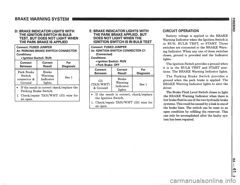
BRAKE WARNING SYSTEM
H CONNECTOR
epair TAN/WHT (33) wire for
D: BRAKE INDICATOR LIGHTS WITH E: BRAKE INDICATOR LlGHTS WITH
THE IGNITION SWITCH IN BULB THE
PARK BRAKE APPLIED, BUT
TEST, BUT DOES NOT
LIGHT WHEN DOES
NOT LIGHT WHEN THE
THE PARK BRAKE IS
APPLIED IGNITION SWITCH IS IN BULB TEST
At: IGNITION SWITCH CONNECTOR 61
If the result is correct, check/replace
the Ignition Switch.
1. Checklrepair TAN/WHT (33) wire for
ClRCUlT OPERATION
Battery voltage is applied to the BRAKE
Warning Indicator when the Ignition Switch is
in RUN, BULB TEST, or START. Three
switches are connected to the BRAKE Warn-
ing Indicator. When any one of these switches
closes, ground is provided and the Indicator
lights.
The Ignition Switch provides a ground when
it is in the BULB TEST and START posi-
tions. The BRAKE Warning Indicator lights.
The Parking Brake Switch provides a
ground when the park brake is applied. The
BRAKE Warning Indicator lights to alert the
driver.
The Brake Fluid Level Switch closes to light
the
BRAKE Warning Indicator when there is
low brake fluid in one of the two hydraulic brake
systems. This could be caused by a leak in one of
the brake lines. The switch can be reset to
an
open condition by refilling the reservoir. This
can only be accomplished after the faulty sys-
tem has been repaired.
Page 1338 of 1825
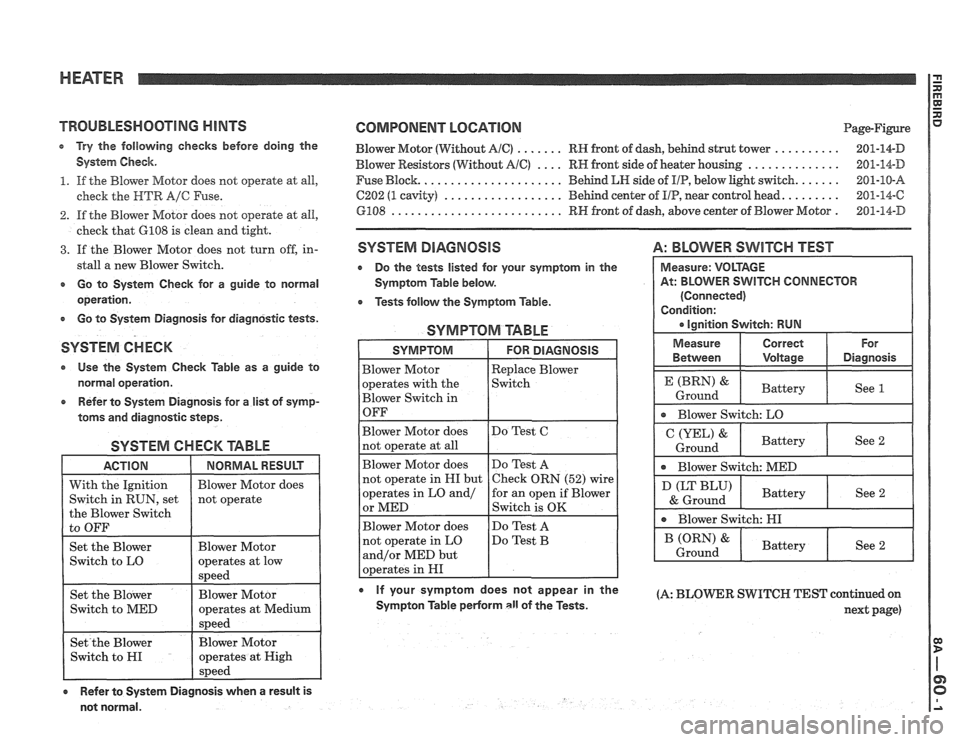
HEATER
TROUBLESMOOTlNG HINTS
e Try the following checlcs before doing the
System Check.
1. If the Blower Motor does not operate at all,
check the
HTR A/C Fuse.
2. If the Blower Motor does not operate at all,
check that
GI08 is clean and tight.
3. If the Blower Motor does not turn off, in-
stall
a new Blower Switch.
r Go to System Check for a guide to normal
operation.
r Go to System Diagnosis for diagnostic tests.
SYSTEM CHECK
Use the System Check Table as a guide to
normal operation.
e Refer to System Diagnosis for a list of symp-
toms and diagnostic steps.
SYSTEM CHECK TABLE
ACTION 1 NORMALRESUU 1
COMPONENT LOCATION Page-Figure
Blower Motor (Without
AlC) ....... RH front of dash, behind strut tower .......... 201-14-D
Blower Resistors (Without AIC) .... RH front side of heater housing .............. 201-14-D
Fuse Block.
..................... Behind LH side of IIP, below light switch. ...... 201-10-8
C202 (1 cavity) .................. Behind center of UP, near control head. ........ 201-14-C
GPO8 .......................... RH front of dash, above center of Blower Motor . 201-14-D
SYSTEM DIAGNOSIS
Do the tests listed for your symptom in the
Symptom Table below.
Tests follow the Symptom Table.
SYMPTOM TABLE
A: BLOWER SWITCH TEST
0 If your symptom does not appear in the (A: BLOmR SWITCH TEST continued on Sympton Table perForm all of the Tests. next page)
not normal. Measure:
VOLTAGE
At: BLOWER
SWITCH CONNECTOR
(Connected)
Condition:
a ignition Switch: RUN
Measure Correct For
Between Voltage Diagnosis
P P
See 1
Blower Switch: LO
&
Ground Battery
See 2
* Blower
Switch: MED
(LT BLU)
& Ground
* Blower Switch: HI
Battery
See 2