1988 PONTIAC FIERO ignition
[x] Cancel search: ignitionPage 1304 of 1825
STARTER AND CHARGING SYSTEM
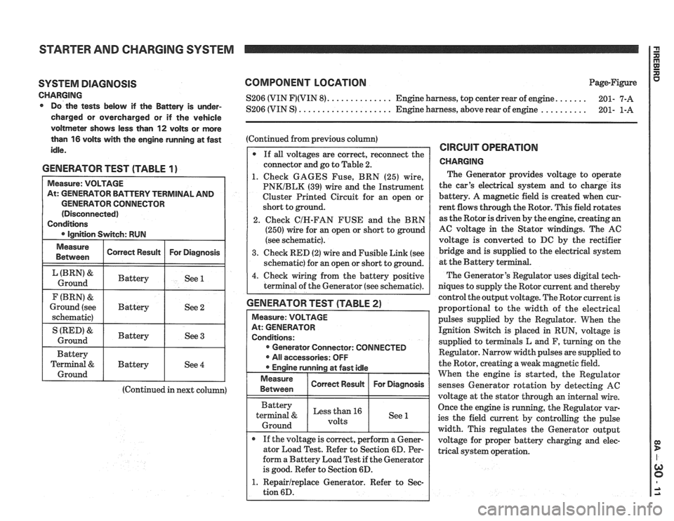
SYSTEM DIAGNOSIS
CHARGING Do the tests below if the Battery is under-
charged or overcharged or if the vehicle
voltmeter shows less than
12 volts or more
than
16 volts with the engine running at fast
idle.
GENERATOR TEST (TABLE 1)
GENERATOR CONNECTOR
(Continued in next column)
COMPONENT LOCATION Page-Figure
...... S206 (VIN F)(VIN 8). ............. Engine harness, top center rear of engine.
201- 7-A
.......... S206 (VIN S) .................... Engine harness, above rear of engine
201- 1-A
(Continued from previous column)
If
all voltages are correct, reconnect the
connector and go to Table 2.
1. Check GAGES Fuse, BRN (25) wire,
PNKIBLK (39) wire and the Instrument
Cluster Printed Circuit for an open or
short to ground.
2. Check
CIH-FAN FUSE and the BRN
(250) wire for an open or short to ground
(see schematic).
3. Check RED (2) wire and Fusible Link (see
schematic) for an open or short to ground.
4. Check wiring from the battery positive
terminal of the Generator (see schematic).
GENERATOR TEST (TABLE 2)
Measure: VOLTAGE
At: GENERATOR
Conditions: Generator Connector: CONNECTED
All accessories: OFF
Engine running at fast idle
Measure I Correct Resuk I For Diagnosis / 1 Between
Battery
terminal
& Less than 16
1 Ground 1 1 See 1
If the voltage is correct, perform a Gener-
ator Load Test. Refer to Section 6D. Per-
form a Battery Load Test if the Generator
is good. Refer to Section 6D.
1. Repairlreplace Generator. Refer to Sec-
tion 6D.
CIRCUIT OPERATION
CHARGING
The Generator provides voltage to operate
the car's electrical system and to charge its
battery. A magnetic field is created when cur-
rent flows through the Rotor. This field rotates
as the Rotor is driven by the engine, creating an
AC voltage in the Stator windings. The AC
voltage is converted to DC by the rectifier
bridge and is supplied to the electrical system
at the Battery ter
The Generator's Regulator uses digital tech-
niques to supply the Rotor current and thereby
control the output voltage. The Rotor current is
proportional to the width of the electrical
pulses supplied by the Regulator. When the
Ignition Switch is placed in RUN, voltage is
supplied to terminals L and F, turning on the
Regulator. Narrow width pulses are supplied to
the Rotor, creating a weak magnetic field.
When the engine is started, the Regulator
senses Generator rotation by detecting
AC
voltage at the stator through an internal wire.
Once the engine is running, the Regulator var-
ies the field current by controlling the pulse
width. This regulates the Generator output
voltage for proper battery charging and elec-
trical system operation.
Page 1309 of 1825
COOLANT FAN I g
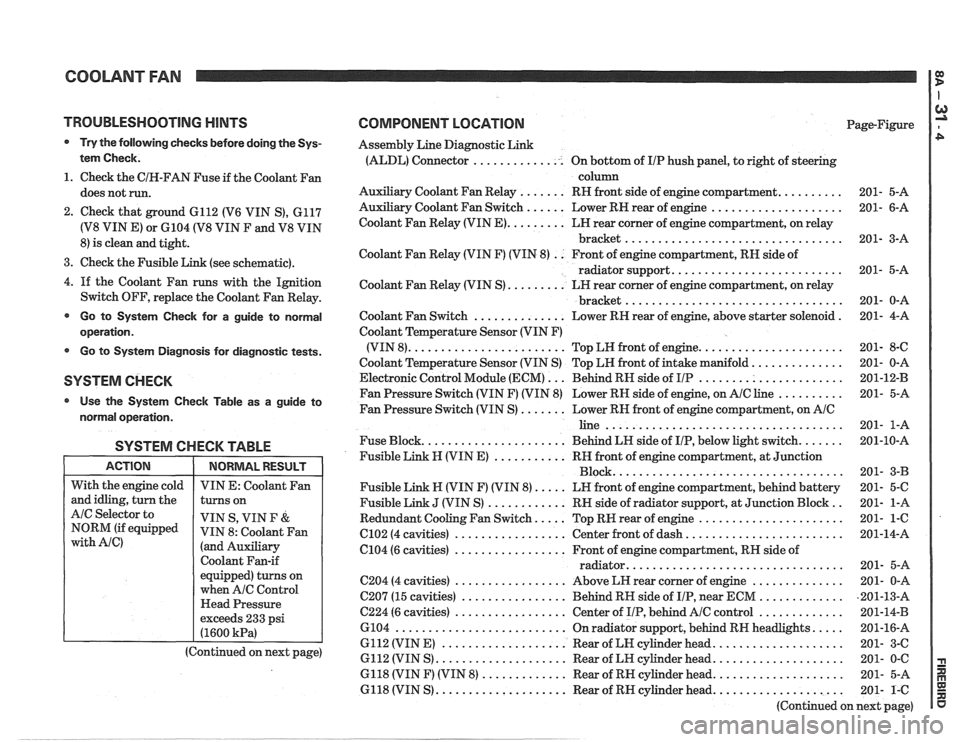
TROUBLESHOOTING HINTS
@ Try the following checks before doing the Sys-
tem Check.
1. Check the CIH-FAN Fuse if the Coolant Fan
does not run.
2. Check that ground 6112 (V6 VIN S), 6117
(V8 VIN E) or 6104 (V8 VIN F and V8 VIN
8) is clean and tight.
3. Check the Fusible Link (see schematic).
4.
If the Coolant Fan runs with the Ignition
Switch OFF, replace the Coolant Fan Relay.
@ Go to System Check for a guide to normal
operation.
Go to System Diagnosis for diagnostic tests.
SYSTEM CHECK
Use the System Checlc Table as a guide to
normal operation.
SYSTEM CHECK TABLE
I ACTION I NORMALRESULT 1
COMPONENT LOCATION Page-Figure
Assembly Line Diagnostic Link
(ALDL) Connector .............. On bottom of IIP hush panel, to right of steering
column
Auxiliary Coolant Fan Relay
....... RH front side of engine compartment. ......... 201- 5-A
Auxiliary Coolant Fan Switch
...... Lower RN rear of engine .................... 201- 6-A
Coolant Fan Relay (VIN
E). ........ LH rear corner of engine compartment, on relay
bracket
................................. 201- 3-A
Coolant Fan Relay (VIN F) (VIN 8)
. . Front of engine compartment, RN side of
radiator support.
......................... 201- 5-A
Coolant Fan Relay (VIN S)
......... LH rear corner of engine compartment, on relay
................................. bracket 201- 0-A
Coolant Fan Switch
.............. Lower RH rear of engine, above starter solenoid . 201- 4-A
Coolant Temperature Sensor (VIN F)
(VIN 8).
....................... Top LW front of engine. ..................... 201- 8-C
Coolant Temperature Sensor (VIN S) Top LH front of intake manifold.
............. 201- 0-A
Electronic Control Module (ECM)
... Behind RN side of IIP ...................... 201-12-B
Fan Pressure Switch (VIN F) (VIN 8) Lower RH side of engine, on
AIC line .......... 201- 5-A
Fan Pressure Switch (VIN S)
....... Lower RN front of engine compartment, on AIC
line .................................... 201- 1-A
Fuse Block.
..................... Behind LN side of IIP, below light switch. ...... 201-10-A
Fusible Link
N (VIN E) ........... RH front of engine compartment, at Junction
Block ................................... 201- 3-B
Fusible Link N (VIN F) (VIN 8).
.... LN front of engine compartment, behind battery 201- 5-C
Fusible Link
J (VIN S) ............ RN side of radiator support, at Junction Block .. 201- 1-A
Redundant Cooling Fan Switch.
.... Top RW rear of engine ...................... 201- 1-6
C102 (4 cavities) ................. Center front of dash. ....................... 201-14-A
6104 (6 cavities)
................. Front of engine compartment, RH side of
................................ radiator. 201- 5-A
C204 (4 cavities) ................. Above LH rear corner of engine .............. 201- 0-A
C207 (15 cavities)
................ Behind RH side of IIP, near ECM ............. ,201-13-A
C224 (6 cavities) ................. Center of IIP, behind AIC control ............. 201-14-B
6104
.......................... On radiator support, behind RN headlights. .... 201-16-A
6112 (VIN E)
................... Rear of LN cylinder head. ................... 201- 3-C
6112 (VIN S)
.................... Rear of LH cylinder head. ................... 201- 0-C
6118 (VIN F) (VIN 8)
............. Rear of RH cylinder head. ................... 201- 5-A
6118 (VIN S)
.................... Rear of RH cylinder head. ................... 201- 1-C
(Continued on next page)
With
the engine cold
and idling, turn the
AIC Selector to
NORM (if equipped
with Ale)
VIN E: Coolant Fan
turns on
VIN S, VIN
F &
VIN 8: Coolant Fan
(and Auxiliary
Coolant Fan-if
equipped) turns on
when
A/C Control
Head Pressure
exceeds 233 psi
(1600
kPa)
(Continued on next page)
Page 1312 of 1825
COOLANT FAN rn
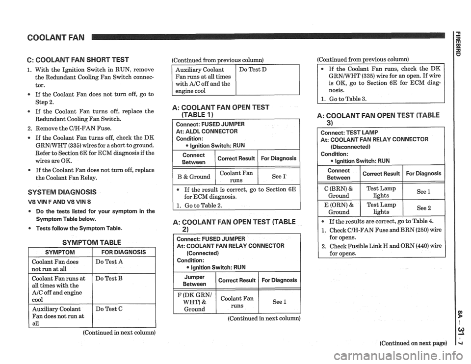
6: COOLANT FAN SHORT TEST
1. With the Ignition Switch in RUN, remove
the Redundant Cooling Fan Switch connec-
tor.
If the Coolant Fan does not turn off, go to
Step
2.
If the Coolant Fan turns off, replace the
Redundant Cooling Fan Switch.
2. Remove the CIR-FAN Fuse.
If the Coolant Fan turns off, check the DK
GRNIWHT
(335) wires for a short to ground.
Refer to Section 6E for ECM diagnosis if the
wires are OK.
a If the Coolant Fan does not turn off, replace
the Coolant Fan Relay.
SYSTEM DlAGNOSlS
V8 VIN F AND V8 VIN 8
Do the tests listed for your symptom in the
Symptom Table below.
Tests follow the Symptom Table.
SYMPTOM TABLE
I SYMPTOM I FORDIAGNOSIS I
I Do Test A I
I not run at aB I I
Coolant Fan runs at
all times with the
A/C off and engine
cool
(Continued in next column)
Do
Test
B
Auxiliary Coolant
Fan does not run at
all
:Continued from previous column)
Fan runs at
all times
with
AIC off and the
Do Test C (Continued
from previous column)
GRNIWNT
(335) wire for an open. If wire
is OK, go to Section 6E for ECM diag-
nosis.
1. Go to Table 3.
A: COOLANT FAN OPEN TEST
(TABLE
1)
At: ALDL CONNECTOR
Condition:
I B &Ground I I See l' I
Connect
Between
If the result is correct, go to Section 6E
for ECM diagnosis.
A: COOLANT FAN OPEN TEST (TABLE
2)
Correct Result
I
Connect: FUSED JUMPER
At: COOLANT FAN RELAY CONNECTOR For
Diagnosis
(Connected)
Condition: lgnition Switch: RUN
Jumper
I Correct Result I For Diagnosis I Between
(DK GRN1 Coolant Fan
WHT) & See 1
1 Ground 1 runs 1 1
A: COOLANT FAN OPEN TEST (TABLE
3) I
Connect: TEST LAMP
At: COOLANT FAN RELAY CONNECTOR
(Disconnected)
Condition:
Connect I Correct Rewn I For Diagnosis I I Between
C (BRN) &
Ground
If the results are correct, go to Table
4.
1. Check CIH-FAN Fuse and BRN (250) wire
for opens.
2. Check Fusible Link H and ORN (440) wire
for opens.
E (ORN)
&
Ground
(Continued in next column)
(Continued on next page)
Test Lamp
lights See
1
Test
Lamp
lights See 2
Page 1313 of 1825
COOLANT FAN
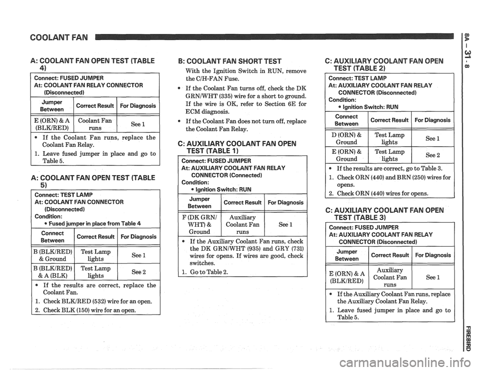
0 If the Coolant Fan runs, replace the
Coolant Fan Relay.
A: COOLANT FAN OPEN TEST (TABLE
4)
Connect: FUSED JUMPER
At: COOLANT FAN RELAY CONNECTOR
(Disconnected)
1. Leave fused jumper in place and go to
Table
5.
A: COOLANT FAN OPEN TEST (TABLE
5 1
Connect: TEST LAMP
At: COOLANT FAN CONNECTOR
(Disconnected)
Condition:
0 Fused jurnper in place from Table 4
For Diagnosis
See 1
Jumper
Between
E (ORN) & A
(BLKIRED)
Connect Correct Result For Diagnosis
Betvveen Correct
Result
coolant an
runs
B (BLKIRED) Test Lamp
1 & Ground 1 lights I See1
B (BLKIRED) Test Lamp
& A (BLK) I lights
If the results are correct, replace the
Coolant Fan.
1. Check BLKIRED (532) wire for an open.
2. Check BLK (150) wire for an open.
B: COOLANT FAN SHORT TEST 6: AUXILIARY COOLANT FAN OPEN
With the Ignition Switch in RUN, remove TEST (TABLE 2)
the CIH-FAN Fuse.
0 If the Coolant Fan turns off, check the DK
GRNIWNT (335) wire for a short to ground.
If the wire is OK, refer to Section 6E for
ECM diagnosis.
If the Coolant Fan does not turn off, replace
the Coolant Fan Relay.
6: AUXILIARY COOLANT FAN OPEN
TEST (TABLE
1)
Connect: FUSED JUMPER
At: AUXILIARY COOLANT FAN RELAY
CONNECTOR (Connected)
Condition:
0 Ianition Switch: RUN Connect:
TEST LAMP
At: AUXILIARY COOLANT
FAN RELAY
CONNECTOR (Disconnected)
Condition: Ignition Switch: RUN
Connect
Between
D (ORN) &
Ground
E (ORN)
&
Ground
Jumper
Between
If the Auxiliary Coolant Fan runs, check
the DK
GRNlWNT (935) and GRY (731)
wires for opens. If wires are good, check
switches.
1. Go to Table 2.
F (DK GRNl
WHT) &
Ground If
the results are correct, go to Table
3.
1. Check ORN (440) and BRN (250) wires for
opens.
2. Check ORN
(440) wires for opens.
Correct Result
Test Lamp
lights
Test Lamp lights
Correct Result For
Diagnosis
See 1
See 2
Auxiliary
Coolant Fan
runs
Connect: FUSED JUMPER
At: AUXILIARY COOLANT FAN RELAY
CONNECTOR (Disconnected)
For
Diagnosis See 1
Jumper
Between
(ORN' & A
(BLKIRED)
6: AUXILIARY COOLANT FAN OPEN
0 If the Auxiliary Coolant Fan runs, replace
the Auxiliary Coolant Fan Relay.
1. Leave fused jumper in place and go to
Table
5.
Correct Result
Auxiliary
Coolant Fan
runs
For Diagnosis
See 1
Page 1314 of 1825
COOLANT FAN
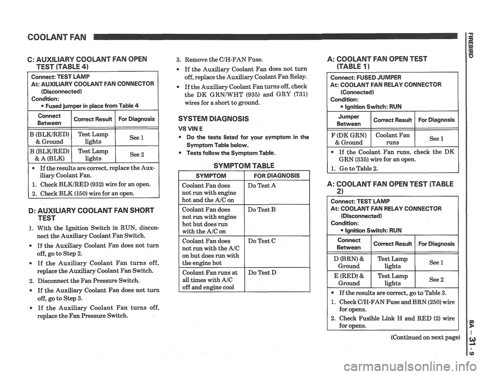
C: AUXILIARY COOLANT FAN OPEN
TEST (TABLE
41
At: AUXILIARY COOLANT FAN CONNECTOR
(Disconnected)
iliary Coolant Fan.
1. Check BLKIRED (932) wire for an open.
2. Check BLK (150) wire for an open.
D: AUXILIARY COOLANT FAN SHORT
TEST
1. With the Ignition Switch in RUN, discon-
nect the Auxiliary Coolant Fan Switch.
If the Auxiliary Coolant Fan does not turn
off, go to Step
2.
If the Auxiliary Coolant Fan turns off,
replace the Auxiliary Coolant Fan Switch.
2. Disconnect the Fan Pressure Switch.
If the Auxiliary Coolant Fan does not turn
off, go to Step
3.
* If the Auxiliary Coolant Fan turns off,
replace the Fan Pressure Switch.
3. Remove the CIN-FAN Fuse. A: COOLANT FAN OPEN TEST
y Coolant Fan does not turn (TABLE 1 )
Auxiliary Coolant Fan Relay.
Coolant Fan turns off, check
the DK
GRNIWRT (935) and GRY (731)
wires for a short to ground.
SYSTEM DIAGNOSIS
V8 VIN E
Do the tests listed for your symptom in the
Symptom Table below.
* Tests follow the Symptom Table.
SYMPTOM TABLE
but does run with
At: COOLANT FAN RELAY CONNECTOR
A: COOLANT FAN OPEN TEST (TABLE
2)
Connect: TEST LAMP
At: COOLANT FAN RELAY CONNECTOR
(Disconnected)
Condition:
Ignition Switch: RUN
Connect
Between
I Conen Resun I For Diagnosis I
Ground lights
* If the results are correct, go to Table 3.
1. Check CIK-FAN Fuse and BRN (250) wire
for opens.
2. Check Fusible Link H and RED (2) wire
(Continued on next page)
Page 1315 of 1825
COOLANT FAN I $
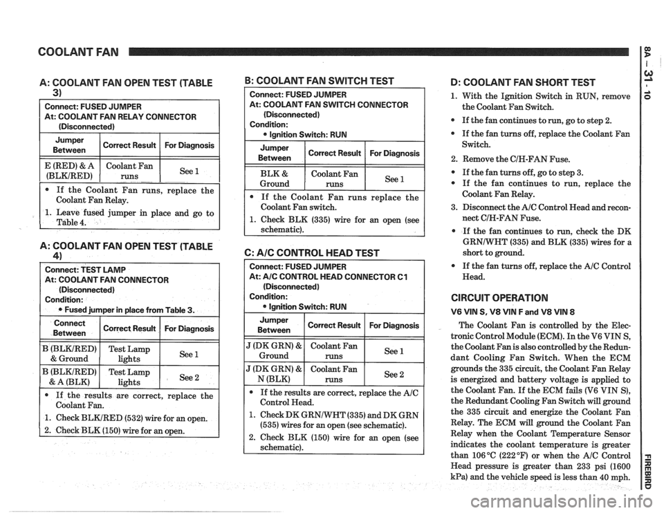
A: COOLANT FAN OPEN TEST (TABLE
3)
Connect: FUSED JUMPER
At: COOLANT FAN RELAY CONNECTOR
(Disconnected)
Jumper Correct Result For Diagnosis
Between
1. Leave fused jumper in place and go to
Table
4.
E (RED) & A
(BLKIRED)
A: COOLANT FAN OPEN TEST (TABLE
41
Connect: TEST LAMP
At: COOLANT FAN CONNECTOR
(Disconnected)
Condition:
Fused jumper in place from Table
3.
If the Coolant Fan runs, replace the
Coolant Fan Relay. Coolant
Fan
runs
-. -. See --
B: COOLANT FAN SWITCH TEST
Connect
Between
B (BLKtRED)
& Ground
B (BLKIRED)
& A (BLK)
Connect: FUSED JUlVlPER
At: COOLANT FAN SWITCH CONNECTOR
(Disconnected)
Condition: lgnition Switch: RUN
Jumper
Between Correct
Result For Diagnosis
Coolant Fan
Ground
runs
If the Coolant Fan runs replace the
Coolant Fan switch.
1. Check BLK (335) wire for an open (see
schematic).
6: AIC CONTROL HEAD TEST
If the results are correct, replace the
Coolant Fan.
1. Check BLKIRED (532) wire for an open.
2. Check BLK (150) wire for an open.
Correct Result
Test Lamp
lights
Test Lamp
lights
Connect: FUSED JUMPER
At:
A/C CONTROL HEAD CONNECTOR Cl
(Disconnected)
Condition:
lgnition Switch: RUN
For Diagnosis
See 1
See 2
Jumper
Between I Correct Result I For Diagnosis I
".' Ground
J (DK GRN) & Coolant Fan See N (BLK) runs
If the results are correct, replace the
AIC
Control Head.
1. Check DK GRNIWHT (335) and DK GRN
(535) wires for an open (see schematic).
2. Check BLK (150) wire for an open (see
schematic).
D: COOLANT FAN SHORT TEST
1. With the Ignition Switch in RUN, remove
the Coolant Fan Switch.
If the fan continues to
run, go to step 2.
If the fan turns off, replace the Coolant Fan
Switch.
2. Remove the CIH-FAN Fuse.
If the fan turns off, go to step 3.
If the fan continues to run, replace the
Coolant Fan Relay.
3. Disconnect the
AIC Control Head and recon-
nect CIH-FAN Fuse.
If the fan continues to run,
check the DK
GRNIWHT (335) and BLK (335) wires for a
short to ground.
If the fan turns off, replace the
AIC Control
Head.
CIRCUIT OPERATION
V6 VIN S, V8 VIN F and V8 VIN 8
The Coolant Fan is controlled by the Elec-
tronic Control Module (ECM). In the V6 VIN S,
the Coolant Fan is also controlled by the Redun-
dant Cooling Fan Switch. When the ECM
grounds the 335 circuit, the Coolant Fan Relay
is energized and battery voltage is applied to
the Coolant Fan.
If the ECM fails (V6 VIN S),
the Redundant Cooling Fan Switch will ground
the 335 circuit and energize the Coolant Fan
Relay. The ECM will ground the Coolant Fan
Relay when the Coolant Temperature Sensor
indicates the coolant temperature is greater
than 106
OC (222 OF) or when the AIC Control
Head pressure is greater than 233 psi (1600
kPa) and the vehicle speed is less than 40 mph.
Page 1318 of 1825
VEHICLE SPEED SENSOR
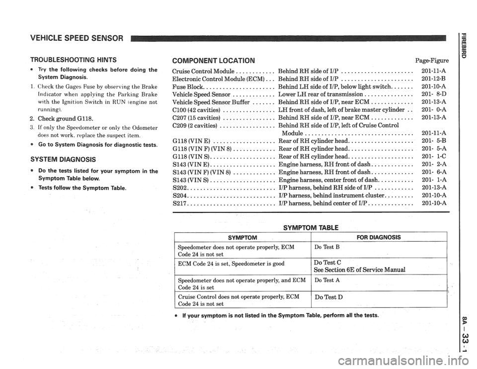
TROUBLESHOOTING HINTS
0 Try the following checks before doing the
System Diagnosis
.
1
. Check the Gages Fuse by observing the Brake
Indicator when applying the Parking Brake
wrth the Ignition Switch in RUN (engine not
running)
.
2 . Check ground 6118 .
3 . If only the Speedometer or only the Odometer
does not work. replace the suspect item
.
Go to System Diagnosis for diagnostic tests .
SYSTEM DlAGNOSlS
Do the tests listed for your symptom in the
Symptom Table below
.
Tests follow the Syrnptom Table .
COMPONENT LOCATION Page-Figure
Cruise Control Module
............ Behind RN side of IlP ...................... 201-11-A
Electronic Control Module (ECM)
... Behind RN side of IIP ...................... 201-12-B
Fuse Block
...................... Behind LN side of IIP. below light switch ....... 201-10-A
Vehicle Speed Sensor
............. Lower LEI rear of transmission ............... 201- 8-D
Vehicle Speed Sensor Buffer
....... Behind RH side of IIP. near ECM ............. 201-13-A
ClOO (42 cavities) ................ LN front of dash. left of brake master cylinder .. 201- 0-A
C207 (15 cavities) ................ Behind RH side of IIP. near ECM ............. 201-13-A
C209 (2 cavities)
................. Behind RN side of IIP. left of Cruise Control
................................. Module 201-11-A
6118 (VIN E)
................... Rear of RH cylinder head .................... 201- 5-B
6118 (VIN F) (VIN 8) ............. Rear of RN cylinder head .................... 201- 5-A
6118 (VIN S)
.................... Rear of RN cylinder head .................... 201- 1-C
S143 (VINE)
.................... Engine harness. RH front of dash ............. 201- 2-A
S143 (VIN F) (VIN
8) ............. Engine harness. RN front of dash ............. 201- 6-A
S143 (VIN S)
.................... Engine harness. center front of dash ........... 201- 1-A
S202
........................... IIP harness. behind RH side of IIP ............ 201-13-A
S204
........................... IIP harness. behind instrument cluster ......... 201-10-A
S217 ........................... IIP harness. behind center of IIP .............. 201-10-A
SYMPTOM TABLE
I SYMPTOM I FOR DIAGNOSIS I
=liter does not operate properly. ECM I Do Test B
code 24 is not set
ECM Code
24 is set. Speedometer is good
e If your symptom is not listed in the Symptom Table. pedorm all the tests .
Do Test C
See Section 6E of Service Manual
Speedometer does not operate properly. and ECM
Code
24 is set
Cruise Control does not operate properly. ECM
Code
24 is not set Do
Test
A
Do Test D
Page 1319 of 1825
VEHICLE SPEED SENSOR
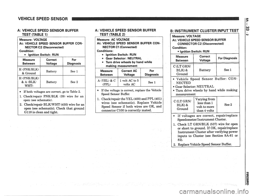
A: VEHICLE SPEED SENSOR BUFFER
TEST (TABLE
1)
At: VEHICLE SPEED SENSOR BUFFER CON-
NECTOR
62 (Disconnected)
Condition:
I e lnnition Switch: RUN I
I ztmz) I Battery I See 1 /
Measure
Between
A: VEHICLE SPEED SENSOR BUFFER
TEST (TABLE
2)
Measure: AC VOLTAGE
At: VEHICLE SPEED SENSOR BUFFER CON-
NECTOR Cl (Connected)
Conditions:
e Ignition Switch: RUN
e Gear Selector: NEUTRAL
e Turn drive wheels by hand while
making measurement
Measure
I Correct AC 1 For
Correct
Voltage
H (PNKJBLK)
& A (BLKJ
WNT)
B: INSTRUMENT CLUSTER INPUT TEST I
For
Diagnosis Measure:
VOLTAGE
At: VEHICLE SPEED SENSOR BUFFER
CONNECTOR C2 (Disconnected)
Condition: lgnition Switch: RUN
* If both voltages are correct, go to Table 2.
1. Checklrepair PNKJBLK (39) wire for an
open (see schematic).
2.
ChecWrepair BLKIWHT (450) wire for an
open (see schematic). Check that ground
6118 is clean and tight. Battery
See
2
Measure
Between Correct I For Diagnosis I I Voltage
Between
A (YEL) & C
(PPL)
( CgEg?' I Battery I See 1
e If the voltage is correct, replace the Vehicle
Speed Sensor Buffer.
1.
ChecWrepair the UEL (400) and PPL (401)
wires (see schematic). Replace Vehicle
Speed Sensor if both wires are OK, and
connector
C100 is correctly mated.
Voltage
1 volt AC to 5
volts
AC
Ground I
Vehicle Speed Sensor Buffer: CON-
NECTED
Gear Selector: NEUTRAL
Diagnosis
See
I 0 Turn drive wheels by hand while making I
measurement
I
If voltages are correct, repairlreplace
SpeedometerIInstrument Cluster.
1. Check LT GRNIBLK (537) wire for open
or short to ground. If OK,
repairireplace
Instrument Cluster after verifying power
inputs to Cluster (see Section
8A-81 or
82).
2. Replace Vehicle Speed Sensor Buffer.
(LT GRN1
BLK' &
Ground
Varying from
less than
5.
volt to more
than 4 volts See 2