1988 PONTIAC FIERO ignition
[x] Cancel search: ignitionPage 1277 of 1825
THROTTLE BODY INJECTION: V8 VIN E
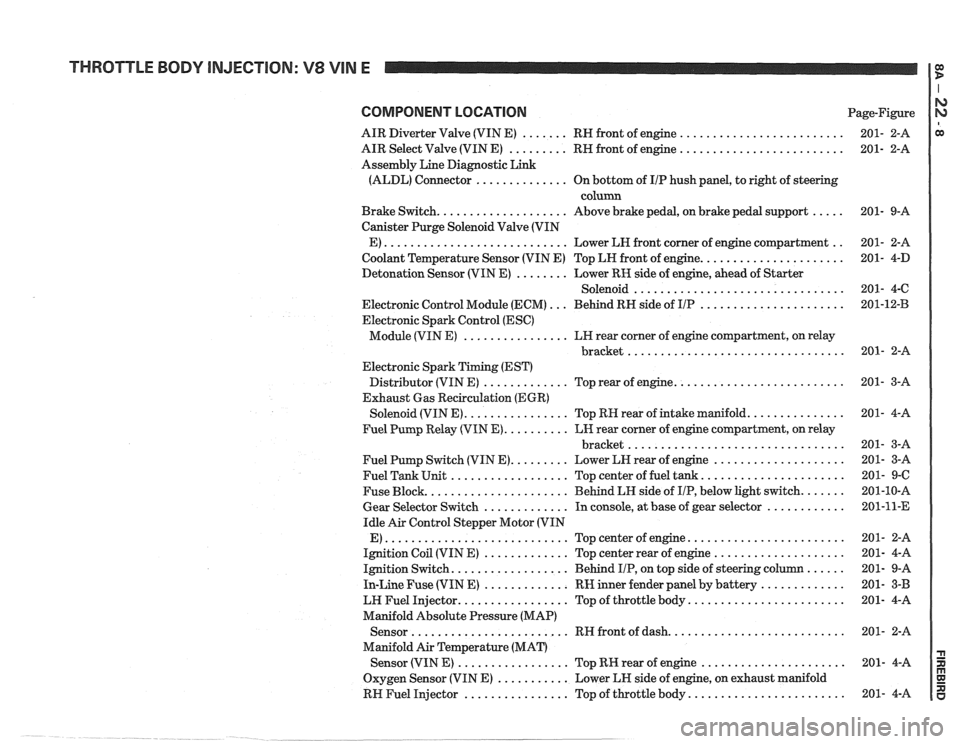
COMPONENT LOCATION Page-Figure
AIR Diverter Valve (VIN E)
....... RH front of engine .........................
AIR Select Valve (VIN E) ......... RH front of engine .........................
Assembly Line Diagnostic Link
(ALDL) Connector
.............. On bottom of IIP hush panel, to right of steering
column
Brake Switch.
................... Above brake pedal, on brake pedal support .....
Canister Purge Solenoid Valve (VIN
E)
............................ Lower LH front corner of engine compartment ..
Coolant Temperature Sensor (VIN E) Top LH front of engine. .....................
Detonation Sensor (VIN E) ........ Lower RK side of engine, ahead of Starter
Solenoid
................................
Electronic Control Module (ECM) ... Behind RH side of IIP ......................
Electronic Spark Control (ESC)
Module (VIN E)
................ LH rear corner of engine compartment, on relay
................................. bracket
Electronic Spark Timing (EST)
Distributor (VIN E)
............. Top rear of engine. .........................
Exhaust Gas Recirculation (EGR)
Solenoid (VIN E).
............... Top RH rear of intake manifold. ..............
Fuel Pump Relay (VIN E). ......... LH rear corner of engine compartment, on relay
................................. bracket
Fuel Pump Switch (VIN E).
........ Lower LH rear of engine ....................
Fuel Tank Unit .................. Top center of fuel tank. .....................
Fuse Block. ..................... Behind LH side of IIP, below light switch. ......
Gear Selector Switch ............. In console, at base of gear selector ............
Idle Air Control Stepper Motor (VIN
E)
............................ Topcenterofengine ........................
Ignition Coil (VIN E) ............. Top center rear of engine ....................
Ignition Switch. ................. Behind IIP, on top side of steering column ......
In-Line Fuse (VIN E) ............. RW inner fender panel by battery .............
LW Fuel Injector. ................ Top of throttle body. .......................
Manifold Absolute Pressure (MAP)
Sensor
........................ RH front of dash. ..........................
Manifold Air Temperature (MAT)
Sensor (VIN
E) ................. Top RK rear of engine ......................
Oxygen Sensor (VIN E) ........... Lower LH side of engine, on exhaust manifold
RH Fuel Injector
................ Top of throttle body. .......................
Page 1283 of 1825
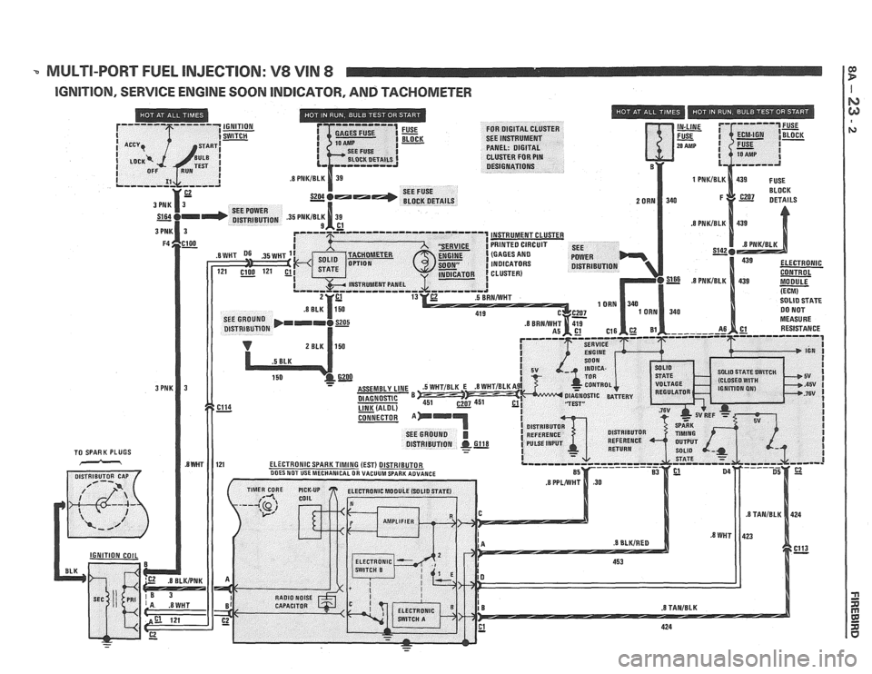
-. MULTI-PORT FUEL INJECTION: V8 VIN 8 I F w
IGNITION, SERVICE ENGINE SOON INDICATOR, AND TACHOMETER I
Page 1289 of 1825
MULTI-PORT FUEL INJECTION: V8 VIN 8 It
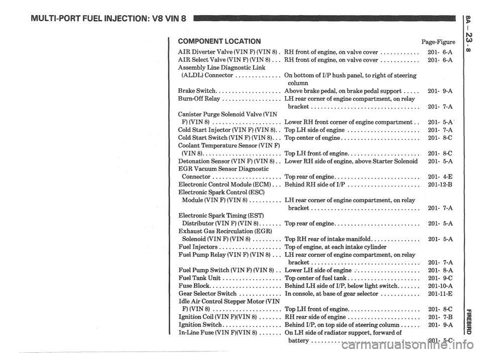
COMPONENT LOCATION Page-Figure
. ............ AIR Diverter Valve (VIN F) (VIN 8)
RN front of engine. on valve cover 201- 6-A
............ AIR Select Valve (VIN F) (VIN 8) ... RW front of engine. on valve cover 201- 6-A
Assembly Line Diagnostic Link
(ALDL) Connector
.............. On bottom of I/P hush panel. to right of steering
column
..... Brake Switch .................... Above brake pedal. on brake pedal support 201- 9-A
Burn-Off Relay
.................. LH rear corner of engine compartment. on relay
bracket
................................. 201- 7-A
Canister Purge Solenoid Valve (VIN
.. F) (VIN 8) ..................... Lower RH front corner of engine compartment 201- 5-A'
.. ...................... Cold Start Injector (VIN F) (VIN 8) Top LH side of engine 201- 7-A
........................ Cold Start Switch (VIN F) (VIN 8) ... Top center of engine 201- 8-6
Coolant Temperature Sensor (VIN F)
...................... (VIN 8) ........................ Top LN front of engine 201- 8-C
Detonation Sensor (VIN F) (VIN 8)
. . Lower RN side of engine. above Starter Solenoid 201- 5-A
EGR Vacuum Sensor Diagnostic
.......................... Connector ..................... Top rear of engine 201- 4-E
...................... Electronic Control Module (ECM) ... Behind RH side of IIP 201-12-B
Electronic Spark Control (ESC)
Module (VIN F) (VIN 8)
.......... LH rear corner of engine compartment. on relay
bracket
................................. 201- 7-A
Electronic Spark Timing (EST)
.......................... Distributor (VIN F) (VIN 8) ....... Top rear of engine 201- 5-A
Exhaust Gas Recirculation (EGR)
............... Solenoid (VIN F) (VIN 8) ......... Top RN rear of intake manifold 201- 5-A
Fuel Injectors
................... Top of engine. at each intake cylinder
Fuel Pump Relay (VIN F) (VIN 8)
... LH rear corner of engine compartment. on relay
bracket
................................. 201- 7-A
.. ................... Fuel Pump Switch (VIN F) (VIN 8)
Lower LH side of engine : 201- 8-A
...................... Fuel Tank Unit .................. Top center of fuel tank 201- 9-C
....... Fuse Block ...................... Behind LH side of IIP. below light switch 201-10-A
............ Gear Selector Switch ............. In console. at base of gear selector 201-11-E
Idle Air Control Stepper Motor (VIN
...................... F) (VIN 8) ..................... Top LN front of engine 201- 8-C
...................... Ignition Coil (VIN F)(VIN 8) ....... RH rear side of engine 201- 7-B
...... Ignition Switch .................. Behind IIP. on top side of steering column 201- 9-A
In-Line Fuse (VIN F)(VIN 8) ....... On LH side of radiator support. forward of
battery
................................. 201- 5-C
Page 1296 of 1825
TROUBLESHOOTING HINTS
STARTER
Try the following checks before doing
the Sys-
tem Diagnosis
.
1 . Check the hydrometer eye that is built into
the vehicle Battery before troubleshooting
the Starter System
.
. Green eye . Battery is charged .
. Dark eye . Battery is discharged . Recharge
Battery
.
- Clear or yellow eye . Battery fluid is low .
Replace Battery .
2 . Check that the Starter Solenoid te
and B and battery
connections are clean and
tight
.
3 . Check that grounds 6100 and 6103 are
clean and tight
.
Go to System Diagnosis for diagnostic tests .
SYSTEM DIAGNOSIS
STARTER
NOTE:
The following tests are designed for
engines and batteries at normal operat-
ing temperatures and assumes that
there are no engine symptoms which
could cause a no start condition
. To use
the tests under other conditions could
result in misdiagnosis
.
Diagnostic steps for the symptorns listed in
the following table are listed after the table
.
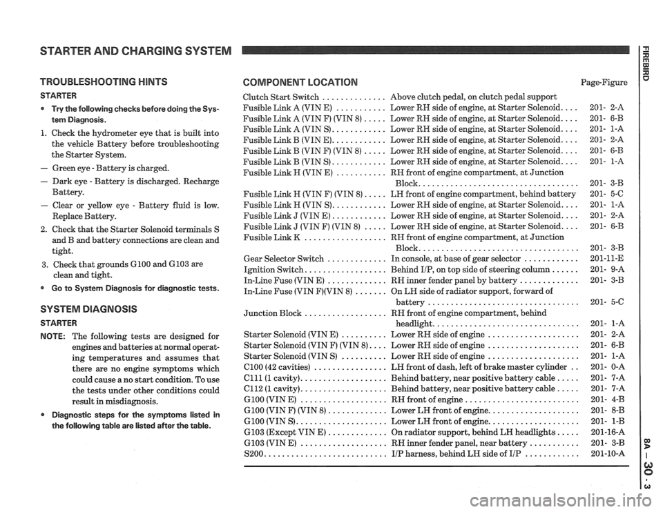
COMPONENT LOCATION Page-Figure
Clutch Start Switch
.............. Above clutch pedal. on clutch pedal support
Fusible Link A (VIN E)
........... Lower RH side of engine. at Starter Solenoid .... 201- 2-A
Fusible Link A (VIN F) (VIN
8) ..... Lower RH side of engine. at Starter Solenoid .... 201- 6-B
Fusible Link A (VIN S)
............ Lower RH side of engine. at Starter Solenoid .... 201- 1-A
Fusible Link B (VIN
E) ............ Lower RH side of engine. at Starter Solenoid .... 201- 2-A
Fusible Link
B (VIN F) (VIN 8) ..... Lower RH side of engine. at Starter Solenoid .... 201- 6-B
Fusible Link B (VIN S)
............ Lower RH side of engine. at Starter Solenoid .... 201- 1-A
Fusible Link
H (VIN E) ........... RN front of engine compartment. at Junction
................................... Block 201- 3-B
Fusible Link
H (VIN F) (VIN 8) ..... LH front of engine compartment. behind battery 201- 5-C
Fusible
Link H (VIN S) ............ Lower RH side of engine. at Starter Solenoid .... 201- 1-A
Fusible Link
J (VIN E) ............ Lower RH side of engine. at Starter Solenoid .... 201- 2-A
Fusible Link
J (VIN F) (VIN 8) ..... Lower RH side of engine. at Starter Solenoid .... 201- 6-B
Fusible Link
K .................. RH front of engine compartment. at Junction
................................... Block 201- 3-B
Gear Selector Switch
............. In console. at base of gear selector ............ 201-11-E
Ignition Switch
.................. Behind IIP. on top side of steering column ...... 201- 9-A
In-Line Fuse (VIN E)
............. RH inner fender panel by battery ............. 201- 3-B
In-Line Fuse (VIN F)(VIN 8) ....... On LN side of radiator support. forward of
battery
................................. 201- 5-C
Junction Block
.................. RH front of engine compartment. behind
headlight
................................ 201- 1-A
Starter Solenoid (VIN
E) .......... Lower RH side of engine .................... 201- 2-A
Starter Solenoid (VIN F) (VIN
8) .... Lower RH side of engine .................... 201- 6-B
Starter Solenoid (VIN S)
.......... Lower RH side of engine .................... 201- 1-A
el00 (42 cavities) ................ LH front of dash. left of brake master cylinder .. 201- 0-A
Clll(1 cavity) ................... Behind battery. near positive battery cable ..... 201- 7-A
el12 (1 cavity) ................... Behind battery. near positive battery cable ..... 201- 7-A
G100 (VIN E) ................... RH front of engine ......................... 201- 4-B
G100 (VIN F) (VIN 8) ............. Lower LH front of engine .................... 201- 8-B
6100 (VIN S) .................... Lower LH front of engine .................... 201- 1-B
6103 (Except VIN
E) ............. On radiator support. behind LH headlights ..... 201-16-A
6103 (VIN
E) ................... RH inner fender panel. near battery ........... 201- 3-B
S200
........................... IIP harness. behind LH side of IIP ............ 201-10-A
Page 1297 of 1825
STARTER AND CHARGING SYSTEM
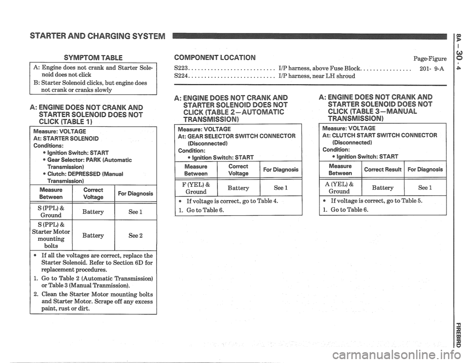
SYMPTOM TABLE
noid does not click
B: Starter Solenoid clicks, but engine does
A: ENGINE DOES MOT CRANK AND
STARTER SOLENOID DOES NOT
Measure: VOLTAGE
At: STARTER
SOLENOID
Conditions:
Ignition Switch: START
Gear Selector: PARK (Automatic
Transmission) Clutch: DEPRESSED
(Manual
Transmission)
Measure
Between
Correct I For Diagnosis I
I (PPL' & I Battery I See 1 I Ground
S (PPL)
& I I
Starter Motor
mounting I Battery I See 2
bolts
If
all the voltages are correct, replace the
Starter Solenoid. Refer to Section
6D for
replacement procedures.
1. Go to Table 2 (Automatic Transmission)
or Table
3 (Manual Tranmission).
2. Clean the Starter Motor mounting bolts
and Starter Motor. Scrape off any excess
paint, rust or dirt.
COMPONENT LOCATION
....... $223. .......................... IIP harness, above Fuse Bbck.
S224. .......................... IIP harness, near LIP shroud Page-Figure
........ 201- 9-A
A: ENGINE DOES MOT CRANK AND
STARTER SOLENOID DOES NOT
CLICK (TABLE 2-AUTOMATlC
TRANSMISSION)
A: ENGINE DOES MOT CRANK AND
STARTER SOLENOID DOES MOT
CLICK (TABLE 3-MANUAL
TRAMSMiSS16N)
Measure:
VOLTAGE
At: GEAR SELECTOR SWITCH CONNECTOR
(Disconnected)
Condition:
Correct 1 For Diagnosis I
If voltage is correct, go to Table 4.
1. Go to Table 6.
(YEL) &
Ground
At: CLUTCH START SWITCH CONNECTOR
(Disconnected)
Battery See 1
Page 1298 of 1825
STARTER AND CHARGING SYSTEM
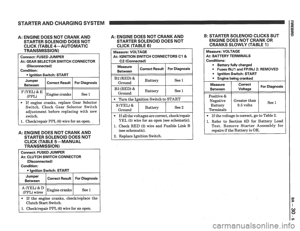
A: ENGINE DOES NOT CRANK AND
STARTER SOLENOID DOES NOT
CLICK (TABLE 4-AUTOMATIC
TRANSMISSION)
Connect: FUSED JUMPER
At: GEAR SELECTOR SWITCH CONNECTOR
(Disconnected)
Condition:
0 Ignition Switch: START
I
Jumper I Corren Resuk I For Diagnosis I Between
I (:::LI& IEngine cranks I See 1 1
If engine cranks, replace Gear Selector
Switch. Check Gear Selector Switch
adjustment before replacing with new
switch.
1. ChecWrepair PPL (6) wire for an open.
A: ENGINE DOES NOT CRANK AND
STARTER SOLENOlD DOES NOT
CLICK (TABLE 5-MANUAL
TRANSMISSION)
Connect: FUSED JUMPER
At: CLUTCH SWITCH CONNECTOR
(Disconnected)
Condition:
I 0 lanition Switch: START I
I :if,",":: 1 Engine cranks I See 1 I
Jumper
Between
If the engine cranks, checklreplace the
Clutch Start Switch.
1. Checklrepair PPL (6) wire for an open.
A: ENGINE DOES NOT CRANK AND B:
STARTER SOLENOID CLICKS BUT
STARTER
SOLENOID DOES NOT ENGINE DOES NOT CRANK OR
CLICK (TABLE 61 CRANKS SLOWLY (TABLE 1)
Correct Result Measure:
VOLTAGE
At: IGNITION SWITCH CONNECTORS
C1 &
C2 (Connected)
For Diagnosis
I Measure ( Correct Result I For Diagnosis 1 Between
I B2 (RED)& I Battery ( See 1 I Ground
I B3 IRED'& I Battery ( See 1 1 Ground
0 Turn the Ignition Switch to START
Measure: VOLTAGE
At: BPirTERV TERMINALS
Conditions: Battery fully charged
0 Fuses lNJ1 and FPIINJ 2: REMOVED
Ignition Switch: START
Engine being cranked
See 2 IYEL' &
Ground
For Diagnosis
See
Measure
Between
Positive &
Negative Battery
Terminals
If
all the voltages are correct, checklrepair
YEL (5) wire for an open (see schematic).
1. Check RED (2) wire and Fusible Link B
(see schematic).
2. Replace Ignition Switch.
Battery
0 If
the voltage is correct, go to Table 2.
1. Refer to Section 6D for Battery Load
Test. Remove Starter Assembly for
repairs if the Battery is
OK.
Correct
Voltage
Greater than
9.5 volts
Page 1299 of 1825
STARTER AND CHARGING SYSTEM
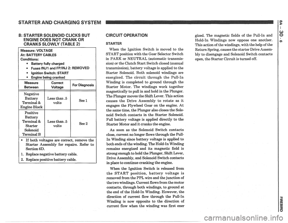
: STARTER SOLENOID CLICKS BUT
ENGINE DOES NOT CRANK OR
CRANKS SLOWLY (TABLE
2)
Battery fully charged
Fuses
lNJl and FPIINJ 2: REMOVED
Starter Assembly for repairs. Refer to
1. Replace negative battery cable.
2. Replace positive battery cable.
CIRCUIT OPERATION
STARTER
Wen the Ignition Switch is moved to the
START position with the Gear Selector Switch
in PARK or NEUTRAL (automatic
transrnis-
sion) or the Clutch Start Switch closed (manual
transmission), battery voltage is applied to the
Starter Solenoid. Both solenoid windings are
energized. The circuit through the Pull-In
Winding is completed to ground through the
Starter Motor. The windings work together
magnetically to pull in and hold in the Plunger.
The Plunger moves the Shift Lever. This action
causes the Drive Assembly to rotate as
it
engages the Flywheel Gear on the engine. At
the same time, the Plunger also closes the Sole-
noid Switch contacts in the Starter Solenoid.
Full battery voltage is applied directly to the
Starter Motor and it cranks the engine.
As soon as the Solenoid Switch contacts
close, current no longer flows through the Pull-
In Winding since battery voltage is applied to
both ends of the winding. The Nold-In Winding
remains energized and its magnetic field is
strong enough to hold the Plunger, Shift Lever,
Drive Assembly, and Solenoid Switch contacts
in place to continue cranking the engine.
When the Ignition Switch is released from
the START position, battery voltage is
removed from the PPL wire and the junction of
the two windings. Current flows from the motor
contacts, through both windings, to ground at
the end of the Hold-In Winding. However, the
direction of current flow through the Pull-In
Winding is now opposite to the direction of
current flow when the winding was first ener
gized. The magnetic fields of the Pull-In and
Hold-In Windings now oppose one another.
This action of the windings, with the help of the
Return Spring, causes the starter Drive Assem-
bly to disengage and Solenoid Switch contacts
open, the Starter Circuit is turned off.
Page 1303 of 1825
STARTER AND CHARGING SYSTEM
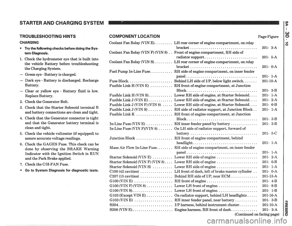
TROUBLESHOOTING HINTS
CHARGING
* Try the following checks before doing the Sys-
tem Diagnosis
.
1 . Check the hydrometer eye that is built into
the vehicle Battery before troubleshooting
the Charging System
.
- Green eye . Battery is charged .
. Dark eye . Battery is discharged . Recharge
Battery
.
- Clear or yellow eye . Battery fluid is low .
Replace Battery .
2 . Check the Generator Belt .
3 . Check that the Starter Solenoid terminal B
and battery connections are clean and tight
.
4 . Check that the Generator connector is tight
and that the Generator battery terminal is
clean and tight
.
5 . Check the vehicle voltmeter (if equipped) to
assure accurate voltage readings
.
6 . Check the GAGES Fuse . This check can be
done by observing the BRAKE Warning
Indicator with the Ignition Switch in RUN
and the Park Brake applied
.
7 . Check the GIN-FAN Fuse .
Go to System Diagnosis for diagnostic tests .
COMPONENT LOCATION Page-Figure
Coolant Fan Relay (VIN
E) ......... LH rear corner of engine compartment. on relay
bracket
................................. 201- 3-A
Coolant Fan Relay (VIN F) (VIN 8)
. . Front of engine compartment. RH side of
radiator support
.......................... 201- 5-A
Coolant Fan Relay (VIN S)
......... LN rear corner of engine compartment. on relay
bracket
................................. 201- 0-A
Fuel Pump In-Line Fuse
........... RH side of engine compartment. on inner fender
panel
................................... 201- 1-A
Fuse Block
...................... Behind LN side of IIP. below light switch ....... 201-10-A
Fusible Link H (VIN E)
........... RH front of engine compartment. at Junction
................................... Block 201- 3-B
Fusible Link
H (VIN S) ............ Lower RN side of engine. at Starter Solenoid .... 201- 1-A
Fusible Link
J (VIN E) ............ Lower RH side of engine. at Starter Solenoid .... 201- 2-A
Fusible Link
J (VIN F) (VIN 8) ..... Lower RH side of engine. at Starter Solenoid .... 201- 6-B
Fusible Link
J (VIN S) ............ RH side of radiator support. at Junction Block .. 201- 1-A
Fusible Link
K .................. RH front of engine compartment. at Junction
................................... Block 201- 3-B
In-Line Fuse (VIN E)
............. RH inner fender panel by battery ............. 201- 3-B
In-Line Fuse (VIN
F)(VIN 8) ....... On LH side of radiator support. forward of
................................. battery 201- 5-6
.................. Junction Block RH
front of engine compartment. behind
................................ headlight 201- 1-A
........ Mass Air Flow In-Line Fuse RR side of engine compartment. on inner fender
................................... panel 201- 1-A
Starter Solenoid (VIN E)
.......... Lower RH side of engine .................... 201- 2-A
Starter Solenoid (VIN F) (VIN
8) .... Lower RH side of engine .................... 201- 6-B
Starter Solenoid (VIN S)
.......... Lower RN side of engine .................... 201- 1-A
el00 (42 cavities) ................ LH front of dash. left of brake master cylinder .. 201- 0-A
C207 (15 cavities)
................ Behind RH side of IIP. near ECM ............. 201-13-A
G100 (VIN E) ................... RH front of engine ......................... 201- 4-B
G100 (VIN F) (VIN 8) ............. Lower LH front of engine .................... 201- 8-B
G100 (VIN S) .................... Lower LH front of engine .................... 201- 1-B
6103 (Except VIN E) ............. On radiator support. behind LH headlights ..... 201-16-A
6.103 (VIN E) ................... RH inner fender panel. near battery ........... 201- 3-B
S204
........................... IIP harness. behind instrument cluster ......... 201-10-A
S206 (VIN
E) .................... Engine harness. RH front of dash ............. 201- 2-A
(Continued on facing page)