1988 PONTIAC FIERO ignition
[x] Cancel search: ignitionPage 1179 of 1825
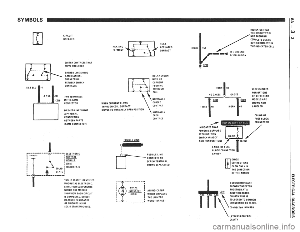
SYMBOLS
CIRCUIT BREAKER
SWITCH CONTACTS THAT
MOVE TOGETHER
DASHED LlNE SHOWS
A MECHANICAL
CONNECTION BETWEEN SWITCH
CONTACTS
~26 IN THE SAME
CONNECTOR
DASHED
LlNE SHOWS
A PHYSICAL
CONNECTION BETWEEN PARTS
(SAME
CONNECTORl
ELECTRONIC
CONTROL
MODULE
(ECM) SOLlO STATE
STATE1 .,, ,,,--=----,-a
"SOLIO STATE" IDENTIFIES
MODULE AS ELECTRONIC.
SIMPLIFIED COMPONENTS
WITHIN THE MOOULE
SHOW HOW EACH CIRCUIT
IS COMPLETED. DO NOT
MEASURE RESISTANCE
OF CIRCUITS
INSIDE SOLlO STATE MODULES. HEAT
HEATING
ACTUATED ELEMENT CONTACT
RELAY SHOWN
WlTH NO
CURRENT FLOWING
THROUGH
COIL
NORMALLY
WHEN CURRENT FLOWS CLOSE0
THROUGH COIL, CONTACT CONTACT
MOVES TO NORMALLY OPEN POSITION
NORMALLY
OPEN
CONTACT
FUSIBLE
LINK
I I
SCREW TERMINAL,
SHOWN SEPARATED
I BAAKE I INDICATOR I AN INDICATOR (RED, ! WHICH DISPLAYS
3 BLK
INDICATES THAT
THE CIRCUITRY IS
NOT SHOWN IN
COMPLETE DETAIL
BUT
IS COMPLETE IN
150 THE INOICATED CELL
SEE GROUND OlSTRlBUTlON
GZOO . -
WlRE CHOICES
FOR OPTIONS
GAGES OR DIFFERENT
SHOWN
AN0 LABELED
COLOR OF
- FUSE BLOCK - - - - - - - . . CONNECTOR
INOICAT / POWER IS SUPPLIED I $ I / WlTH IGNITION SWITCH IN ACCY /' AN0 RUN POSITIONS
LABEL OF FUSE
BLOCK CONNECTOR
CAVITY
DIODE CURRENT CAN
FLOW ONLY IN
N- THE DIRECTION
OF THE ARROW
3 CONNECTORS ARE
SHOWN CONNECTED
TOGETHER AT A
JUNCTION BLOCK.
FOURTH
WIRE IS
SOLDERED TO COMMON
CONNECTION ON BLOCK.
CONNECTOR NUMBER
LETTERS FOR EACH
CAVITY
Page 1186 of 1825
TROUBLESHOOTING TESTS m r rn 0
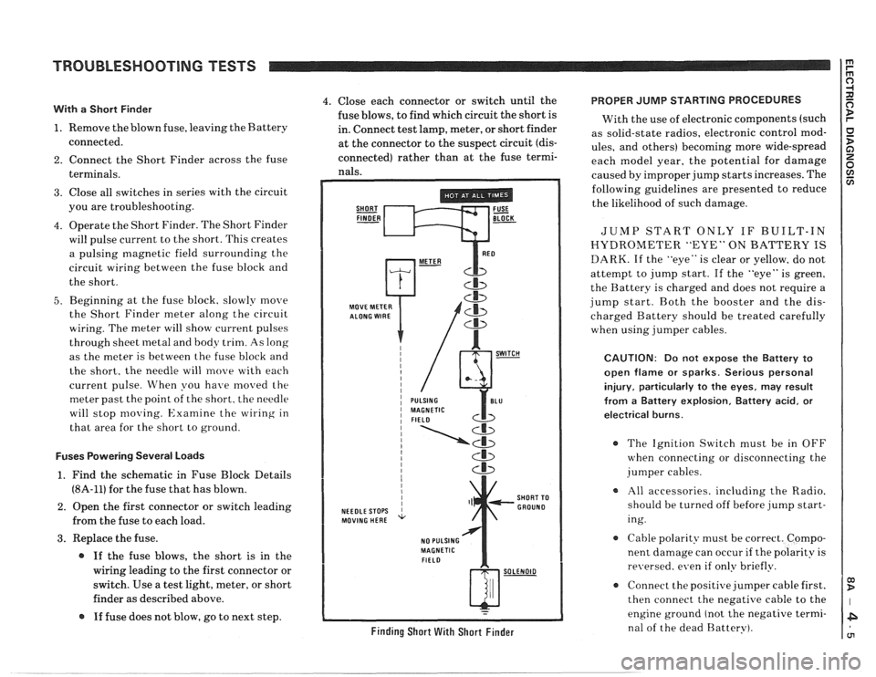
With a Short Finder
1. Remove the blown fuse, leaving the Battery
connected.
2. Connect the Short Finder across the fuse
terminals.
3. Close all switches in series with the circuit
you are troubleshooting.
4. Operate the Short Finder. The Short Finder
will pulse current to the short. This creates
a pulsing magnetic field surrounding the
circuit wiring between the fuse block and
the short.
5. Beginning at the fuse block. slowly move
the Short Finder meter along the circuit
wiring. The meter will show current pulses
through sheet
inetal and body trim. As long
as the meter is between the fuse block and
the short, the needle will move with each
current pulse. When you have
moved the
meter past the point of the short. the needle
will stop
moving. Examine the wiring in
that area for the short to ground.
Fuses Powering Several Loads
1. Find the schematic in Fuse Block Details
(8A-11) for the fuse that has blown.
2. Open the first connector or switch leading
from the fuse to each load.
3. Replace the fuse.
@ If the fuse blows, the short is in the
wiring leading to the first connector or
switch. Use a test light, meter, or short
finder as described above.
@ If fuse does not blow, go to next step.
4. Close each connector or switch until the PROPER JUMP STARTING PROCEDURES
fuse blows, to find which circuit the short is
With the use of electronic components (such
in. Connect test lamp, meter, or short finder
as solid-state radios, electronic control
mod- at the connector to the suspect circuit (dis- ules, and others) becoming more wide-spread
connected) rather than at the fuse termi- each model year, the potential for damage nals. caused by improper jump starts increases. The
SHORT FUSE FINDER - BLOCK -
MOVE METER
NEEDLE STOPS
MOVING HERE
NO PULSING
MAGNETIC
FIELD
Cb
SHORT TO
GROUND
w-
Finding Short With Short Finder
following guidelines are presented to reduce
the likelihood of such damage.
JUMP START ONLY IF BUILT-IN
HYDROMETER "EYE" ON BATTERY IS
DARK. If the "eye" is clear or yellow, do not
attempt to jump start. If the "eye" is green,
the Battery is charged and does not require a
jump start. Both the booster and the dis-
charged Battery should be treated carefully
when using jumper cables.
CAUTION: Do not expose the Battery to
open flame or sparks. Serious personal
injury, particularly
to the eyes, may result
from
a Battery explosion, Battery acid, or
electrical burns.
The Ignition Switch must be in OFF
when connecting or disconnecting the
jumper cables.
All accessories. including the Radio.
should be turned off before jump start-
ing.
Cable polarity must be correct. Compo-
nent damage can occur
if the polarity is
re~~ersed. even if only briefly.
a Connect the positive jumper cable first.
then connect the negative cable to the
engine ground (not the negative termi-
nal of the dead Battery).
Page 1188 of 1825
REPAIR PROCEDURES
Fusible Links
In addition to circuit breakers and fuses,
some circuits use fusible links to protect the
wiring. Like fuses, fusible links are "one time
"
protection devices that will melt and create an
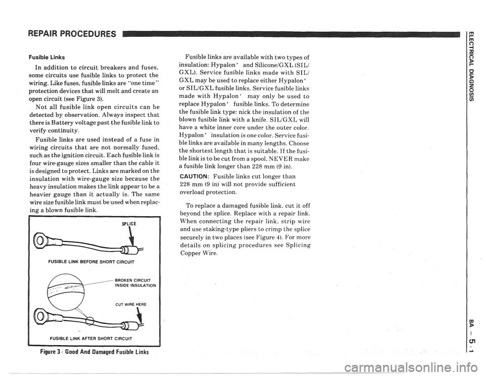
open circuit (see Figure
3).
Not all fusible link open circuits can be
detected by observation. Always inspect that
there is Battery voltage past the fusible link to
verify continuity.
Fusible links are used instead of a fuse in
wiring circuits that are not normally fused,
such as the ignition circuit. Each fusible link is
four wire-gauge sizes smaller than the cable it
is designed to protect. Links are marked on the
insulation with wire-gauge size because the
heavy insulation makes the link appear to be a
heavier gauge than it actually is. The same
wire size fusible link must be used when replac-
ing a blown fusible link.
FUSIBLE LINK BEFORE SHORT CIRCUIT
, BROKEN CIRCUIT INSIDE INSULATION
Fusible links are available with two types of
insulation: Hypalon
bnd SiliconelGXL (SILI
GXL). Service fusible links made with SILI
GXL may be used to replace either Hypalon "
or SILIGXL fusible links. Service fusible links
made with
Hypalonday only be used to
replace Hypalon
"fusible links. To determine
the fusible link type: nick the insulation of the
blown fusible link with a knife.
SILIGXL will
have a white inner core under the outer color.
Hypalon
"nsulation is one color. Service fusi-
ble links are available in many lengths. Choose
the shortest length that is suitable.
If the fusi-
ble link is to be cut from a spool, NEVER make
a fusible link longer than 228 mm
(9 in).
CAUTION: Fusible links cut longer than
228 mm
(9 in) will not provide sufficient
overload protection.
To replace a damaged fusible link, cut it off
beyond the splice. Replace with a repair link.
When connecting the repair link. strip wire
and use staking-type pliers to crimp the splice
securely in two places (see Figure
4). For more
details on splicing procedures see Splicing
Copper Wire.
R SHORT CIRCUIT
Figure 3 - Good And Damaged Fusible Links
-- - - - - -- - - - - -- - - -
Page 1209 of 1825
POWER DISTRIBUTION
CIRCUIT OPERATION
Electrical power for the car is provided by the
Generator when the engine is running. The
schematic diagram shows how each circuit gets
its power. For more details about the Gener-
ator, and connections to the Battery and
Starter, see Starter and Charging System, Sec-
tion
8A-30.
The car's Power Distribution System con-
sists of Fusible Links, Fuses, Circuit Breakers,
the Light Switch and the Ignition Switch. Fusi-
ble Links are short pieces of wire to which they
supply power. They are covered with a special
high-temperature insulation. When conducting
a high current, the Fusible Link will melt and
stop current flow. They are designed to protect
the car's electrical system from electrical
shorts where it is not protected by the Circuit
Breakers and Fuses. See Fuse Block Details
and Light Switch Details for complete wiring to
the first component in each circuit.
The Ignition Switch has six positions, five of
which have detents. The BULB TEST position
is after the RUN position and just before the
START position. BULB TEST does not have a
detent. As shown in the schematic, circuits
which are supplied from the Ignition Switch are
On (Hot) for different switch positions. Indi-
vidual schematics show their fuses supplied
from headings such as "Not In Run. "The head-
ing corresponds to the Ignition Switch position
in which power is On.
Page 1211 of 1825
POWER DISTRIBUTION
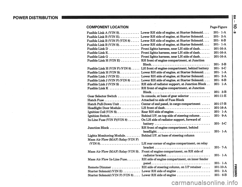
COMPONENT LOCATlON Page-Figure
Fusible Link A (VIN S)
............ Lower RH side of engine. at Starter Solenoid ....
Fusible Link B (VIN E) ............ Lower RH side of engine. at Starter Solenoid ....
Fusible Link B (VIN F) (VIN 8) ..... Lower RH side of engine. at Starter Solenoid ....
............ Fusible Link B (VIN S) Lower
RH side of engine. at Starter Solenoid ....
Fusible Link D .................. Front lights harness. near LH side of dash ......
Fusible Link E ................... Front lights harness. near LH side of dash ......
Fusible Link G .................. Front lights harness. near LH side of dash ......
Fusible Link H (VIN E) ........... RH front of engine compartment. at Junction
Block
...................................
Fusible Link N (VIN F) (VIN 8) ..... LN front of engine compartment. behind battery
Fusible Link H (VIN S)
............ Lower RH side of engine. at Starter Solenoid ....
J (VIN E) ............ Lower RH side of engine, at Starter Solenoid ....
J (VIN F) (VIN 8) ..... Lower RH side of engine, at Starter Solenoid ....
J (VIN S) ............ RH side of radiator support. at Junction Block ..
.................. Fusible Link K RN front of engine compartment. at Junction
Block
...................................
Gear Selector Switch ............. In console, at base of gear selector ............
Hatch Fuse ..................... Attached to side of Fuse Block
Hatch Pull-Down Unit
............ Center of end panel, in cargo compartment .....
Headlight Door Module ........... LH front of dash ...........................
Ignition Coil (VIN S) .............. Rear RH side of engine ......................
Ignition Switch .................. Behind IIP. on top side of steering column ......
In-Line Fuse (VIN F)(VIN 8) ....... On LH side of radiator support. forward of
................................. battery
.................. Junction Block RH front of engine compartment. behind
................................ headlight
Lights Monitoring Module
......... Behind IIP. at base of steering column
Mass Air Flow (MAF) Relay (VIN
F)
........................ (VIN 8) LH rear corner of engine compartment, on relay
................................. bracket
Mass Air Flow (MAF) Relay (VIN S)
. Front of engine compartment. on RH side of
radiator bracket
..........................
Mass Air Flow In-Line Fuse ........ RN side of engine compartment, on inner fender
panel
...................................
Remote Dimmer ................. RH side of steering column. on IIP retainer .....
Starter Solenoid (VIN E) .......... Lower RH side of engine ....................
Starter Solenoid (VIN F) (VIN 8) .... Lower RH side of engine ....................
Page 1250 of 1825
MULTI-PORT FUEL INJECTION: V6 VIN S
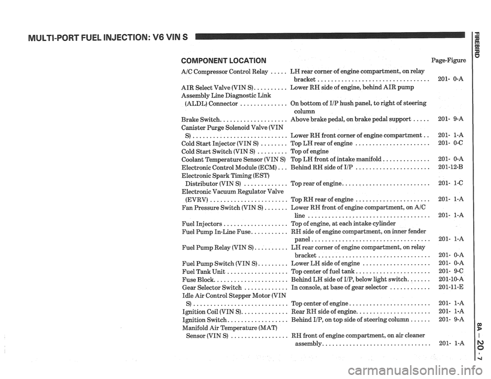
COMPONENT LOCATION
AIC Compressor Control Relay ..... LH rear corner of engine compartment, on relay
................................. bracket
AIR Select Valve (VIN S)
.......... Lower RN side of engine, behind AIR pump
Assembly Line Diagnostic Link
(ALDL) Connector
.............. On bottom of IIP hush panel, to right of steering
column
Brake Switch.
................... Above brake pedal, on brake pedal support .....
Canister Purge Solenoid Valve (VIN
............................ .. S) Lower RH front
corner of engine compartment
Cold Start Injector (VIN S)
........ Top LH rear of engine ......................
Cold Start Switch (VIN S) ......... Top of engine
Coolant Temperature Sensor (VIN S) Top LN front of intake manifold.
.............
Electronic Control Module (ECM) ... Behind RH side of IIP ......................
Electronic Spark Timing (EST)
......................... Distributor (VIN S) ............. Top rear of engine.
Electronic Vacuum Regulator Valve
(EVRV)
....................... TopRHrearofengine ......................
Fan Pressure Switch (VIN S) ....... Lower RH front of engine compartment, on AIC
line ....................................
Fuel Injectors ................... Top of engine, at each intake cylinder
Fuel Pump In-Line Fuse.
.......... RH side of engine compartment, on inner fender
panel
...................................
Fuel Pump Relay (VIN S) .......... LH rear corner of engine compartment, on relay
................................. bracket
Fuel Pump Switch (VIN S)
......... Lower LH side of engine ....................
Fuel Tank Unit .................. Top center of fuel tank ......................
Fuse Block. ..................... Behind LH side of IIP, below light switch. ......
Gear Selector Switch ............. In console, at base of gear selector ............
Idle Air Control Stepper Motor (VIN
S)
............................ Topcenterofengine ........................
Ignition Coil (VIN S). ............. Rear RH side of engine. .....................
Ignition Switch. ................. Behind IIP, on top side of steering column ......
Manifold Air Temperature (MAT)
................. Sensor (VIN S) RH front of engine compartment, on air cleaner
............................... assembly. Page-Figure
Page 1264 of 1825
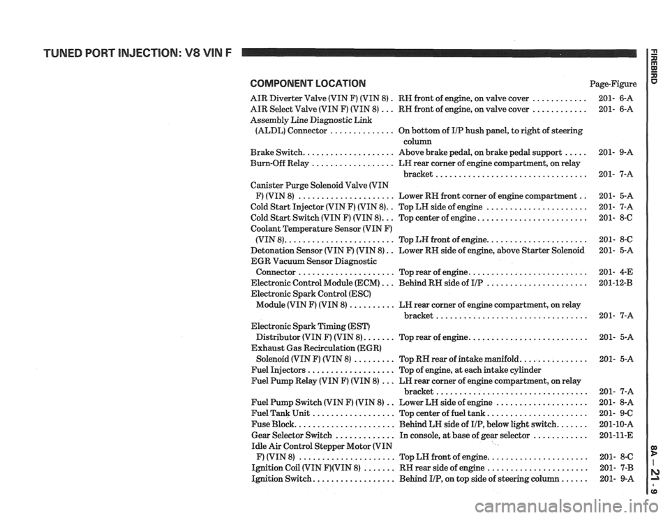
COMPONENT LOCATION Page-Figure
AIR Diverter Valve (VIN F) (VIN 8)
. RN front of engine, on valve cover ............ 201- 6-A
AIR Select Valve (VIN F) (VIN 8)
... RN front of engine, on valve cover ............ 201- 6-A
Assembly Line Diagnostic Link
(ALDL) Connector
.............. On bottom of IIP hush panel, to right of steering
column
Brake Switch.
................... Above brake pedal, on brake pedal support ..... 201- 9-A
Bum-Off Relay
.................. LN rear comer of engine compartment, on relay
bracket
................................. 201- 7-A
Canister Purge Solenoid Valve (VIN
F) (VIN 8)
..................... Lower RN front corner of engine compartment .. 201- 5-A
Cold Start Injector (VIN F) (VIN 8).
. Top LH side of engine ...................... 201- 7-A
.. ....................... Cold Start Switch (VIN F) (VIN 8). Top center of engine. 201- 8-6
Coolant
Temperature Sensor (VIN F)
..................... (VIN 8). ....................... Top LN front of engine. 201- 8-C
Detonation Sensor (VIN F) (VIN 8)
. . Lower RN side of engine, above Starter Solenoid 201- 5-A
EGR Vacuum Sensor Diagnostic
......................... Connector ..................... Top rear of engine. 201-
4-E
Electronic Control Module (ECM)
... Behind RN side of IIP ...................... 201-1243
Electronic Spark Control (ESC)
Module (VIN F) (VIN 8)
.......... LN rear corner of engine compartment, on relay
............................... bracket.. 201- 7-A
Electronic Spark Timing (EST)
Distributor (VIN
F) (VIN 8). ...... Top rear of engine. ......................... 201- 5-A
Exhaust Gas Recirculation (EGR)
Solenoid (VIN
F) (VIN 8) ......... Top RN rear of intake manifold. .............. 201- 5-A
Fuel Injectors
................... Top of engine, at each intake cylinder
Fuel Pump Relay (VIN
F) (VIN 8) ... LN rear corner of engine compartment, on relay
bracket
................................. 201- 7-A
Fuel Pump Switch (VIN
F) (VIN 8) .. Lower LN side of engine .................... 201- 8-A
Fuel Tank Unit
.................. Top center of fuel tank ...................... 201- 9-C
Fuse Block.
..................... Behind LH side of IIP, below light switch. ...... 201-10-A
Gear Selector Switch
............. In console, at base of gear selector ............ 201-11-E
Idle Air Control Stepper Motor (VIN
F) (VIN 8)
..................... Top LN front of engine. ..................... 201- 8-C
Ignition Coil (VIN
F)(VIN 8) ....... RN rear side of engine ...................... 201- 7-B
Ignition Switch.
................. Behind IIP, on top side of steering column ...... 201- 9-A
Page 1271 of 1825
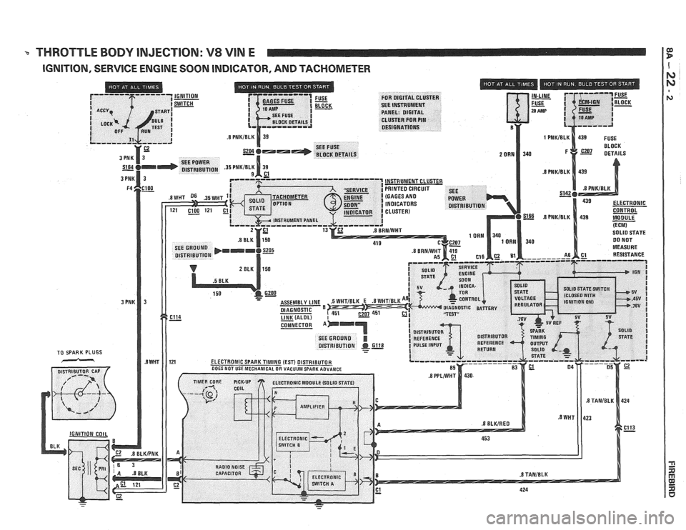
THROTTLE BODY INJECTION: V8 VIN E IF
IGNITION, SERVICE ENGINE SOON INDICATOR, AND TACHOMETER