1988 PONTIAC FIERO ignition
[x] Cancel search: ignitionPage 971 of 1825
6E-18 DRIVEABILITY AND EMISSIONS - FUEL INJECRON
CCP (Carbon Canister Purge)
This displays "ON" when the canister purge
solenoid is commanding purge. Some display duty
cycle from
0-1008.
2nd Gear
This displays the state of the 2nd gear switch.
Yes=2nd gear applied. It remains applied in 3rd and
4th gears.
3rd Gear
This displays the state of the 3rd gear switch.
Yes= 3rd gear applied. It remains applied in 4th gear.
4th Gear
This displays the state of the 4th gear switch.
Yes
= 4th gear applied.
Fan Request
State of the AJC fan control switch is displayed. It
should read "yes" when fan is requested. Some
engines may display the state of the 2nd fan, if used.
Power Steering Pressure Switch
This reading displays the state of switch, and may
vary with the tool used, and the type of switch
installed on the vehicle. The important thing is that
the reading changes state (switches) when the
steering is moved against the stops.
Electronic Control Module (ECM)
This section describes the ECM and the
information sensors in the system. Figure
4 shows
the operating conditions which the ECM may sense
and the systems that the ECM may control. (See
specific engines to determine which are applicable
to
that engine.)
Fuel Control System
The ECM controls the aidfuel delivery to the
combustion chamber by controlling the fuel flow
through the
injector(s).
Electric Fuel Pump (In-tank)
The in-tank fuel pump is controlled by the ECM.
When ignition is turned "ON", the pump will run for 2
seconds, then stop unless the ECM is receiving
ignition pulses, as when cranking or running.
Evaporative Emission ControI
This system has a canister which stores fuel vapor
from the fuel tank. The fuel vapor is removed from the
canister and consumed in the normal combustion
process when the engine is running. This system is
used on all engines and may or may not be controlled
by the ECM.
ilectronic Spark Timing (EST)
This system is controlled by the ECM, which
controls spark advance (timing), and is used on all
engines.
SECTION B - DRIVEABILIW SYMPTOMS Electronic Spark
Control (ESC)
Always start with Section "A" "Diagnostic Circuit
Check" before proceeding to the driveability
symptoms or an emissions test failure. Section "A"
checks the ECM, which may cause the driveability
problem. A definition of each symptom is included.
This will then lead to the most probable causes of the
driveability problem.
SECTION C - COMPONENT SYSTEMS
There are many component systems that are used
to control fuel and emissions. Section
"C" introduces
each component system or control with a general
description, diagnosis, and on-vehicle service.
Each of the Section "C" diagnosis sections contain
information on how the "ScanJ' tool can be used for
diagnosing a particular component when a trouble
code has not been set. (example: Section
"Cl" under
diagnosis will explain how the "Scan" tool can be used
for diagnosis as well as what the normal readings
would be for the
ECM sensors.) This
system uses a knock sensor in connection
with the ECM to control spark timing, to allow the
engine to have maximum spark advance without
spark knock. This improves driveability and fuel
economy, but will retard spark
if detonation (spark
knock) is detected.
Air Injection Reaction (A.I.R.)
The system provides additional oxygen to the
exhaust gases to continue the combustion process.
The system also supplies additional air to the catalytic
converter under certain conditions. The A.I.R. system
is not on all engines.
Early Fuel Evaporation (EFE)
The EFE system heats the engine induction
system electrically or with exhaust gas during cold
Page 973 of 1825
6E-12 DRIVEABILITY AND EMISSIONS - FUEL INJECUION
and MPH) for abbreviations used in this Section, but
all types are acceptable.
NA/F - AI WFUEL (NF RATIO)
A.I.R.
- AIR INJECTOR REACTION SYSTEM - Air
flow from pump is directed into engine exhaust
manifold
and/or converter to reduce exhaust
emissions.
ALDL - ASSEMBLY LINE DIAGNOSTIC LINK - Used
at assembly to evaluate Computer Command Control,
and for service to flash the "Service Engine Soon"
light
if there are trouble codes. It also is used by
"Scan" tools to obtain ECM serial data.
BARO - BAROMETRIC ABSOLUTE PRESSURE
SENSOR
- Reads atmospheric pressure.
B + - Battery Positive Terminal (12 Volts) or
system voltage with the engine running
(approximately 13.8
v.)
CALPAK - A device used with fuel injection to
allow fuel delivery in the event of a PROM or ECM
malfunction.
CALIBRATOR - (PROM) - An electronic component
that can be
specifically programmed to meet engine
operating requirements for a
specific vehicle model.
It plugs into the Engine Control Module
(ECM).
CCC - COMPUTER COMMAND CONTROL - has an
electronic control module to control airlfuel and
emission systems.
CLCC - CLOSED LOOP CARBURETOR CONTROL -
Used to describe oxygen sensor to ECM to MIC
solenoid circuit operation.
C3I - Computer Controlled Coil Ignition. Produces
the ignition spark without the aid of an ignition
distributor.
CCP - CONTROLLED CANISTER PURGE - ECM
controlled solenoid valve that permits manifold
vacuum to purge the evaporative emissions from the
charcoal canister.
CID - CUBIC INCH DISPLACEMENT - Used to
describe engine size.
UL OR ULOOP - "CLOSED LOOP" - Describes ECM
fuel control when using oxygen sensor information.
COOLANT TEMPERATURE SENSOR - Device that
senses the engine coolant temperature, and passes
that information to the engine control module.
CONV. - CATALYTIC CONVERTER, THREE-WAY -
EXHAUST CONVERTER. Containing platinum and
palladium to speed up conversion of
HC and CO, and
rhodium to accelerate conversion of NO,.
CO - CARBON MONOXIDE - One of the pollutants
found in engine exhaust.
6V - CRANKCASE VENTlhaflON - Prevents fumes
in crankcase from passing into the atmosphere, by
drawing them into the intake manifold and burning
them in the the combustion process.
DIAGNOSTIC CODE - Pair of numbers obtained
from flashing "Service Engine Soon" light or
displaying on a "Scan" tool. This code can be used to
determine the system malfunction.
DIAGNOSTIC TERM. - Lead of ALDL Connector
which is grounded to get a Trouble Code.
It is
grounded with the engine running to enter the "Field
Service Mode".
DIS - Direct Ignition System. Produces the
ignition spark without the aid of an ignition
distributor.
DVM (10 Meg.) - Digital Voltmeter with 10 Million
ohms resistance
- used for measurement in electronic
systems.
DWELL - The amount of time (recorded on a dwell
meter in degrees of crankshaft rotation) that current
passes through a closed switch; for example, ignition
contact points or internal switch in an electronic
control module.
EAC - ELECTRIC AIR CONTROL - Used on A.I.R.
system to direct air flow to air switching valve or to
atmosphere.
EAS - ELECTRIC AIR SWITCHING - used to direct air
flow to catalytic converter or exhaust ports of the
engine.
ECM - ENGINE CONTROL MODULE (ELECTRONIC) -
A metal case (located in passenger compartment)
containing electronic circuitry which electrically
controls and monitors airlfuel and emission systems
on computer command control, and turns
"ON" the
"Service Engine Soon" light when a malfunction
occurs in the system.
EFI - ELECTRONIC FUEL INJECTION - Computer
Command Control using throttle body fuel injection.
EGR - EXHAUST GAP REClRCUbATlON - Method of
reducing NO, emission levels by causing exhaust gas
to be added to airlfuel mixture in combustion
chamber, thus cooling combustion.
EECS - EVAPORATIVE EMISSIONS CONTROL
SYSTEM
- Used to prevent gasoline vapors in the fuel
tank from entering the atmosphere.
EFE - EARLY FUEL EVAPORATION - Method of
warming the intake manifold during cold engine
operation. Provides efficient airlfuel mixing.
ENERGIZEIDE-ENERGIZE - When current is passed
through a coil (energized) such as the canister purge
solenoid, the plunger is pulled into the solenoid.
Page 974 of 1825
DRIVEABILIW AND EMISSIONS - FUEL INJECTION 6E-13
When the voltage to the solenoid is turned off, (de-
energized), a spring raises the plunger.
ESC - ELECTRONIC SPARK CONTROL - Used to
sense detonation and retard spark advance when
detonation occurs.
EST - ELECTRONIC SPARK TIMING - ECM
controlled timing of ignition spark.
EVRV - ELECTRONIC VACUUM REGULAWR
VALVE - Controls EGR vacuum.
FED - FEDEWL - VehicleIEngine available in all
states except California.
GROUND - The negative (-) side of the battery.
Also could be a wire (conductor) shorted to ground.
HC - HYDROCARBONS - One of the pollutants
found in engine exhaust.
HIGH IMPEDANCE VOLTMETER - Mas high
opposition to the flow of electrical current.
Good for
reading circuits with low current flow, such as found
in electronic systems because it allows tests to be
made without affecting the circuit.
HE1 - HIGH ENERGY IGNITION - A distributor that
uses an electronic module and pick-up coil in place of
contact points.
Hg - MERCURY - A calibration material used as a
standard for vacuum measurement.
IAC - IDLE AIR CONTROL - A valve installed in the
throttle body of fuel injected systems and controlled by
the ECM to regulate idle speed.
IDEAL MIXWRE - The airlfuel ratio which provides
the best performance, while maintaining maximum
conversion of exhaust emissions. Typically it is
14.7:1.
ID1 - INTEGRATED DIRECT IGNITION - Produces the
ignition spark without the aid of an ignition
distributor or spark plug wires.
IDLE AIR BLEED VALVE - Controls the amount of
air let into the idle fuel mixture prior to the mixture
entering the carburetor idle system, when the
MIC
solenoid is energized.
ILC - IDLE LOAD COMPENSATOR - Device used to
control throttle angle during long deceleration, such
as coasting down a long grade; it extends at wide open
throttle position or to prevent engine stalls at idle.
INPUTS - Information from sources (such as
coolant temperature sensors, exhaust oxygen sensor,
etc.) to the ECM that indicate how the systems are
performing.
INTERMITTENT - Occurs now and then; not
continuously. In electrical circuits, refers to
occasional open, short, or ground.
I.P. - INSTRUMENT PANEL
ISC - IDLE SPEED CONTROL - Regulates throttle
valve position to control idle speed. Idle speed is
controlled by the ECM and is not adjustable.
KMIHR - KILOMEnR PER HOUR - A metric unit
measuring speed needed to travel distance of one
kilometer (1000 meters) in one hour.
L - LITER - A metric unit of capacity.
L4 - FOUR CYLINDER IN-LINE ENGINE
MAF - MASS AIR FLOW - Sensor which measures
the amount of air entering the engine.
MALFUNCTION - A problem that causes the
system to operate incorrectly. Typical malfunctions
are wiring harness opens or shorts, failed sensors or
circuit components.
MANIFOLD VACUUM SENSOR - Indicates vacuum
in the intake manifold by measuring the pressure in
intake manifold in relation to barometric pressure. It
is also called a differential pressure sensor because
it
measures the difference between the two pressures. It
puts out a voltage which is highest when the vacuum
is highest. The maximum voltage is between 4 and 5
volts.
MAP - MANIFOLD ABSOLUTE PRESSURE SENSOR -
Reads pressure changes in intake manifold with
reference to zero pressure. It puts out a voltage which
is highest when the pressure is highest. The
maximum voltage is between
4 and 5 volts.
MAT - Manifold Air Temperature Sensor.
Measures temperature of air in the intake manifold.
MIC - MIXTURE CONTROL
MEM-CAL
- MEMORY CALIBRATOR - Contains
specific calibrations to meet the requirements of a
specific engine.
MFI - MULTlPORT FUEL INJECnON - Individual
injectors for each cylinder are mounted in the intake
manifold. The injectors are fired in groups rather than
individually.
MIXTURE CONTROL (MIC) SOLENOID - Device,
installed in carburetor, to regulate the airlfuel ratio.
MODE - A particular state of operation.
MPH - MILES PER HOUR - A unit measuring speed
needed to travel distance of one mile (5280 feet) in one
hour.
N.C. - NORMALLY CLOSED - State of relay contacts
or solenoid plunger when no voltage is applied.
N-rn - NEWTON METER (Torque) - A metric unit
describing force.
Page 977 of 1825
6E-16 DRIVEABILIW AND EMISSIONS - FUEL INJECTION
BODY BODY
1. OPEN SECONDARY LBCK YlNGE ON CONNECTOR
2. REMOVE TERMINAL USING TOOL
PUSH TO
RELEASE
A. SLIP NEW SEAL ONTO WIRE.
EAL
6. PUSH TERMINAL AND CONNECTOR AND
ENGAGE LOCKING TANGS.
Figure
6 - Weather-Pack Terminal Repair
Compact Three
The compact three connector, which looks similar
to a Weather-pack connector, is not sealed and is used
where resistance to the environment is not required.
This type of connector most likely is used at the air
control solenoid, Use the standard method when
repairing a terminal. Do not use the Weather-pack
terminal tool J-28742,
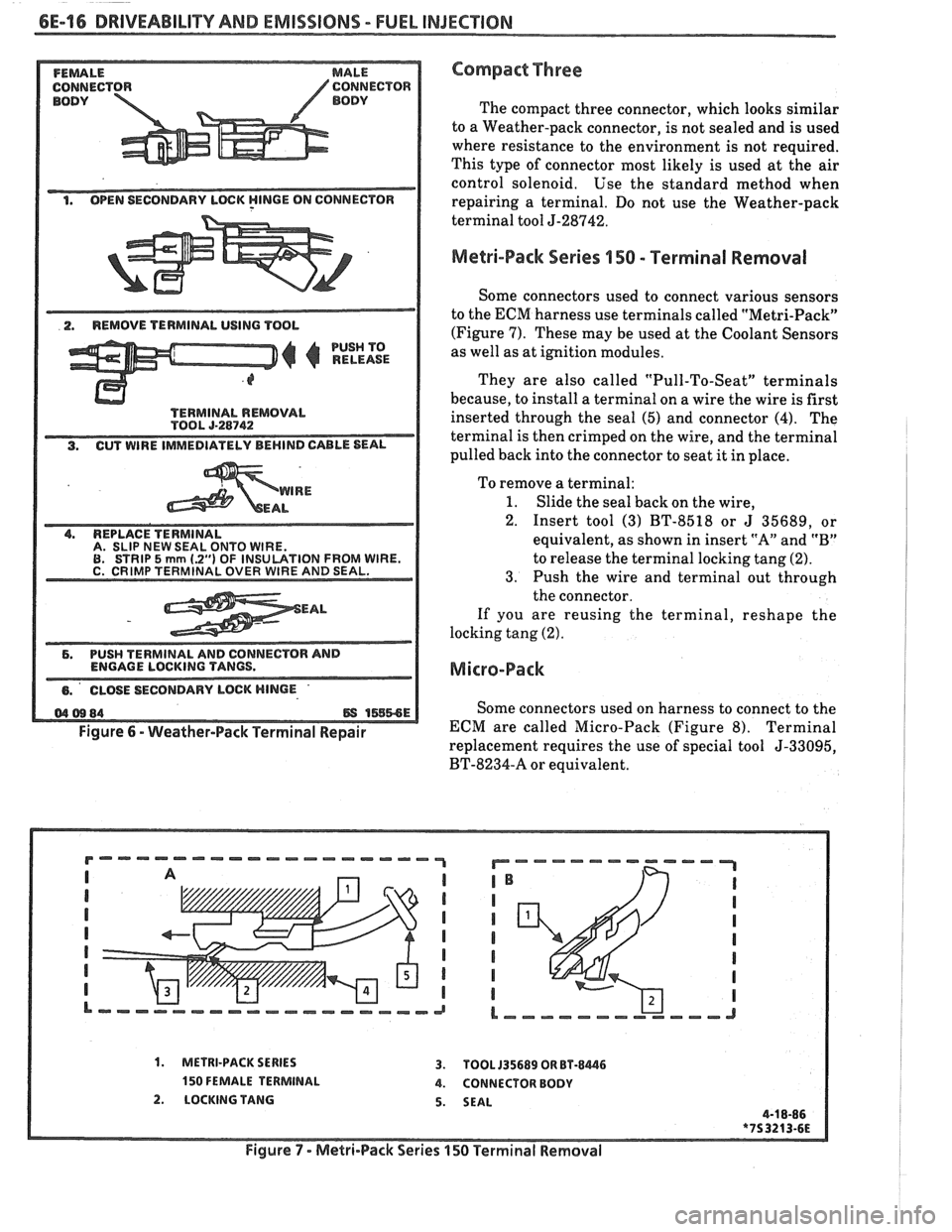
Melri-Pack Series 150 - Terminal Removal
Some connectors used to connect various sensors
to the ECM harness use terminals called "Metri-Pack"
(Figure 7). These may be used at the Coolant Sensors
as well as at ignition modules.
They are also called "Pull-To-Seat" terminals
because, to install a terminal on a wire the wire is first
inserted through the seal (5) and, connector
(4). The
terminal is then crimped on the wire, and the terminal
pulled back into the connector to seat it in place.
To remove a terminal:
1. Slide the seal back on the wire,
2. Insert tool (3) BT-8518 or
J 35689, or
equivalent, as shown in insert "A" and "B"
to release the terminal locking tang (2).
3. Push the wire and terminal out through
the connector.
If you are reusing the terminal, reshape the
locking tang (2).
Micro-Pack
Some connectors used on harness to connect to the
ECM are called Micro-Pack (Figure 8). Terminal
replacement requires the use of special tool
5-33095,
BT-8234-A or equivalent.
1. METRI-PACK SERIES 3. TOOL 135689 OR BT-8446
150 FEMALE TERMINAL 4. CONNECTOR BODY
2. LOCKING TANG 5. SEAL
Figure
7 - Metri-Pack Series 150 Terrninal Removal
Page 981 of 1825
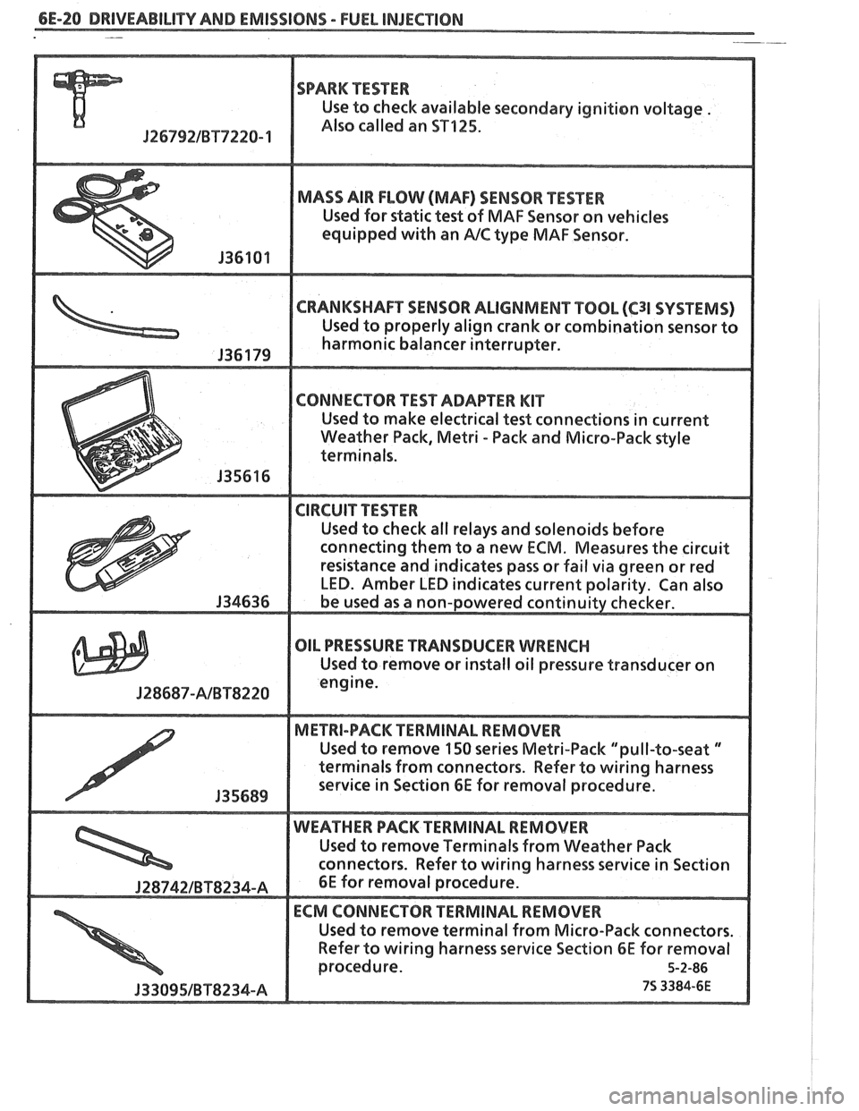
6E-20 DRIVEABILITY AND EMISSIONS - FUEL INJECnION -
SPARK TESTER
Use to check available secondary ignition voltage .
Jf 6792lBT7228- 1 Also called an ST125.
MADS AIR FLOW (MAF) SENSOR PESTER
Used for static test of MAF Sensor on vehicles
equipped
with an PJC type MAF Sensor.
CRANKSHAFT SENSOR ALIGNMENT TOOL (C31 SVSf EMS)
Used "t properly align crank or combination sensor to
harmonic balancer interrupter.
connecting them to a new
ECM. Measures the circuit
OIL PRESSURE TRANSDUCER WRENCH
Used to remove or install oil pressure transducer on
J28687-AlBTS228
Used to remove 150 series Metri-Pack "pull-to-seat "
terminals from connectors. Refer to wiring harness
Used to remove Terminals
from Weather Pack
Refer
to wiring harness service Section 6E for removal
Page 1123 of 1825
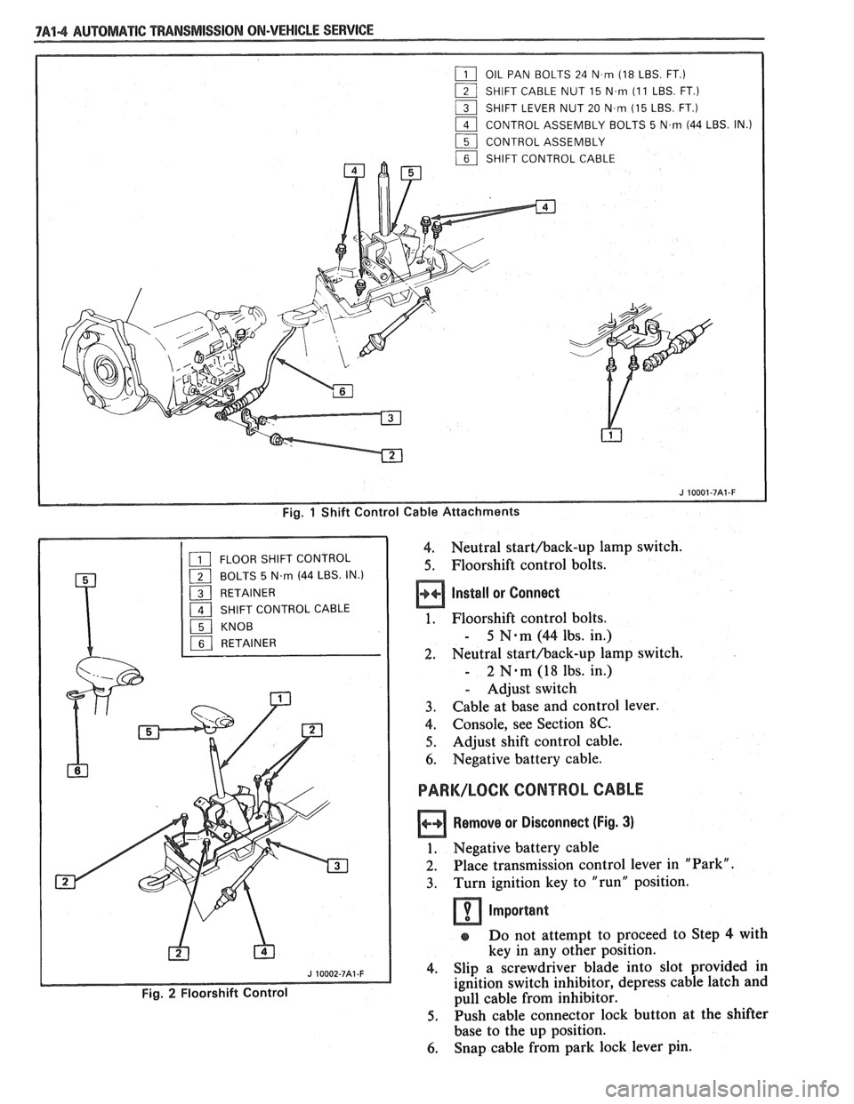
7A44 AUTOMATIC "PANSMISSION ON-VEHICLE SERVICE
Fig. 1 Shift Control Cable Attachments
4. Neutral starthack-up lamp switch.
5. Floorshift control bolts.
Install or Connect
1. Floorshift control bolts.
- 5 N-m (44 lbs. in.)
2. Neutral starthack-up lamp switch.
- 2 N.m (18 lbs. in.)
- Adjust switch
3. Cable at base and control lever.
4. Console, see Section 8C.
5. Adjust shift control cable.
6. Negative battery cable.
PARK/LOCK CONTROL CABLE
Remove or Disconnect (Fig. 3)
1. Negative battery cable
2. Place transmission control lever in "Park".
3. Turn ignition key to "run" position.
Important
s Do not attempt to proceed to Step 4 with
key in any other position.
4. Slip a screwdriver blade into slot provided in
ignition switch inhibitor, depress cable latch and
pull cable from inhibitor.
5. Push cable connector lock button at the shifter
base to the up position.
6. Snap cable from park lock lever pin.
Page 1124 of 1825
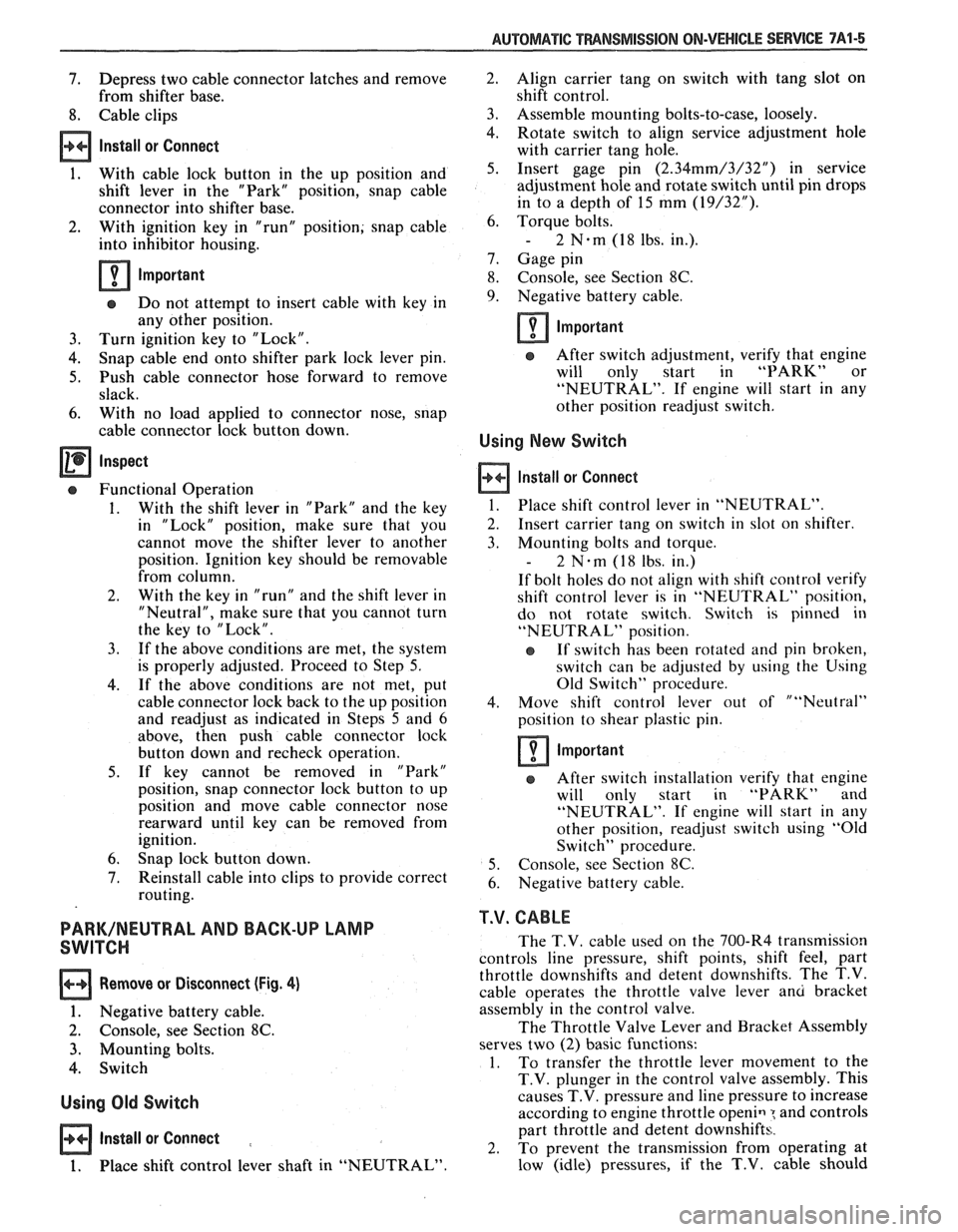
AUTOMATIC TMNSMISSION ON-VEHICLE SERVICE 7A1-5
7. Depress two cable connector latches and remove
from shifter base.
8. Cable clips
Install or Connect
1. With cable lock button in the up position and
shift lever in the "Park" position, snap cable
connector into shifter base.
2. With ignition key in "run" position; snap cable
into inhibitor housing.
Important
e Do not attempt to insert cable with key in
any other position.
3. Turn ignition key to "Lock".
4. Snap cable end onto shifter park lock lever pin.
5. Push cable connector hose forward to remove
slack.
6. With no load applied to connector nose, snap
cable connector lock button down.
Inspect
Functional Operation
1. With the shift lever in "Park" and the key
in "Lock" position, make sure that you
cannot move the shifter lever to another
position. Ignition key should be removable
from column.
2. With the key in "run" and the shift lever in
"Neutral", make sure that you cannot turn
the key to "Lock".
3. If the above conditions are met, the system
is properly adjusted. Proceed to Step
5.
4. If the above conditions are not met, put
cable connector lock back to the up position
and readjust as indicated in Steps
5 and 6
above, then push cable connector lock
button down and recheck operation.
5. If key cannot be removed in "Park"
position, snap connector lock button to up
position and move cable connector nose
rearward until key can be removed from
ignition.
6. Snap lock button down.
7. Reinstall cable into clips to provide correct
routing.
PARK/NEUTRAL AND BACK-UP LAMP
SWITCH
Remove or Disconnect (Fig. 4)
1. Negative battery cable.
2. Console, see Section 8C.
3. Mounting bolts.
4. Switch
Using Old Switch
Install or Connect :
1. Place shift control lever shaft in "NEUTRAL" Align
carrier tang on switch with tang slot on
shift control.
Assemble mounting bolts-to-case, loosely.
Rotate switch to align service adjustment hole
with carrier tang hole.
Insert gage pin
(2.34mm/3/32") in service
adjustment hole and rotate switch until pin drops
in to a depth of 15 mm
(19/32").
Torque bolts.
- 2 N.m (1 8 lbs. in.).
Gage pin
Console, see Section
8C.
Negative battery cable.
Important
After switch adjustment, verify that engine
will only start in
"PARK" or
"NEUTRAL". If engine will start in any
other position readjust switch.
Using New Switch
Install or Connect
1. Place shift control lever in "NEUTRAL".
2. Insert carrier tang on switch in slot on shifter.
3. Mounting bolts and torque.
- 2 N-m (18 lbs. in.)
If bolt holes do not align with shift control verify
shift control lever is in "NEUTRAL" position,
do not rotate switch. Switch is pinned in
"NEUTRAL" position.
e If switch has been rotated and pin broken,
switch can be adjusted by using the Using
Old Switch" procedure.
4. Move shift control lever out of ""Neutral"
position to shear plastic pin.
Important
After switch installation verify that engine
will only start in "PARK" and
"NEUTRAL". If engine will start in any
other position, readjust switch using "Old
Switch" procedure.
5. Console, see Section
8C.
6. Negative battery cable.
T.V. CABLE
The T.V. cable used on the 700-R4 transmission
controls line pressure, shift points, shift feel, part
throttle downshifts and detent downshifts. The T.V.
cable operates the throttle valve lever
anu bracket
assembly in the control valve.
The Throttle Valve Lever and Bracket Assembly
serves two
(2) basic functions:
1. To
transfer the throttle lever movement to the
T.V. plunger in the control valve assembly. This
causes T.V. pressure and line pressure to increase
according to engine throttle
openiq : and controls
part throttle and detent downshifts.
2. To prevent the transmission from operating at
low (idle) pressures, if the
T.V. cable should
Page 1174 of 1825
INTRODUCTION
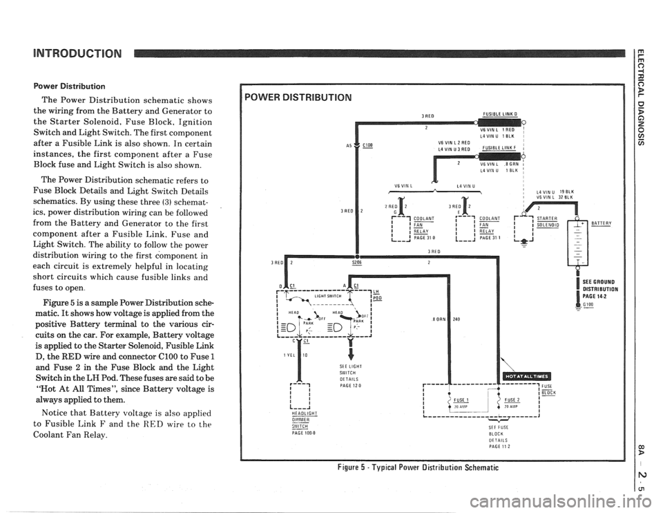
Power Distribution
The Power Distribution schematic shows
the wiring from the Battery and Generator to
the Starter Solenoid, Fuse Block, Ignition
Switch and Light Switch. The first component
after a Fusible Link is also shown. In certain
instances, the first component after a Fuse
Block fuse and Light Switch is also shown.
The Power Distribution schematic refers to
Fuse Block Details and Light Switch Details
schematics. By using these three
(3) schemat-
ics, power distribution wiring can be followed
from the Battery and Generator to the first
component after a Fusible Link. Fuse and
Light Switch. The ability to follow the power
distribution wiring to the first component in
each circuit is extremely helpful in locating
short circuits which cause fusible links and
fuses to open.
Figure
5 is a sample Power Distribution sche-
matic.
It shows how voltage is applied from the
positive Battery terminal to the various cir-
cuits on the car. For example, Battery voltage
is applied to the Starter Solenoid, Fusible Link
D, the
RED wire and connector ClOO to Fuse 1
and Fuse 2 in the Fuse Block and the Light
Switch in the
LH Pod. These fuses are said to be
"Not At All Times", since Battery voltage is
always applied to them.
Notice that Battery voltage is
also applied
to Fusible Link
F and the RED wire to the
Coolant Fan Relay.
L4VIN U 1 ELK I
i VSVIN L 32 BLK
DISTRIBUTION
SkE LIGHT
HEADLIGHT
--
PAGE 100 0 BLOCK DETAILS PAGE 11 2
Figure 5 -Typical Power Distribution Schematic