1988 PONTIAC FIERO oil
[x] Cancel search: oilPage 45 of 1825
18-2 AIR CONDITIONING
SYSTEM GONIPONENE - FFUNCnIONAL
Compressor
All compressors are belt driven from the engine
crankshaft through the compressor clutch pulley. The
compressor pulley rotates without driving the com-
pressor shaft until an electromagnetic clutch coil is
energized. When voltage is applied to energize the
clutch coil, the clutch plate and hub assembly is
drawn rearward toward the pulley. The magnetic
force locks the clutch plate and pulley together as one
unit to drive the compressor shaft.
As the compressor shaft is driven, it compresses
the low-pressure refrigerant vapor from the evaporator
into a high-pressure, high-temperature vapor. Carried
with the refrigerant is the refrigerant oil which is used
to lubricate the compressor. Complete compressor
overhaul procedures can be found in Section
ID of the
General Service Manual.
Pressure Relief Valve
The compressor is equipped with a pressure
relief valve which is placed in the system as a safety
factor. Under certain conditions, the refrigerant on the
discharge side may exceed the designed operating
pressure. To prevent system damage, the valve is
designed to open automatically at approximately
3036
kPa (440 psi). Conditions that might cause this valve
to open (defective high pressure cut-off switch, inop-
erative electric cooling fan, etc.) should be corrected,
and the refrigerant oil and refrigerant should be
replaced as necessary.
A muffler is used on some refrigerant systems to
reduce compressor noises from high or low pressure
vibrations.
Condenser Gore
The condenser assembly in front of the radiator
is made up of coils which carry the refrigerant TO
cooling fins to provide rapid transfer of heat. The air
passing through the condenser cools the high-pressure
refrigerant vapor causing it to condense to a liquid.
Expansion (Orifice) Tube
The plastic expansion tube, with its mesh screen
and orifice, is located in the evaporator inlet pipe at
the liquid line connection. It provides a restriction to
the high-pressure liquid refrigerant in the liquid line,
metering the flow of refrigerant to the evaporator as a
low-pressure liquid. The expansion tube and orifice
are protected from contamination by filter screens on
both inlet and outlet sides. The tube is serviced only
as a replacement assembly.
When the engine is turned "OFF" with the
A/C
system operating, the refrigerant in the system will
flow from the high-pressure side of the expansion tube (orifice) to the low-pressure side until the pressure
is
equalized. This may be detected as a faint sound of
liquid flowing (hissing) for 30 to
60 seconds and is a
normal condition.
Evaporator Gore
The evaporator is a device which cools and
dehumidifies the air before it enters the car. High-
pressure liquid refrigerant flows through the expan-
sion tube (orifice) into the low-pressure area of the
evaporator. The heat in the air passing through the
evaporator core is transferred to the cooler surface of
the core, thereby cooling the air. As the process of
heat transfer from the air to the evaporator core sur-
face is taking place, any moisture (humidity) in the air
condenses on the outside surface of the evaporator
core and is drained off as water.
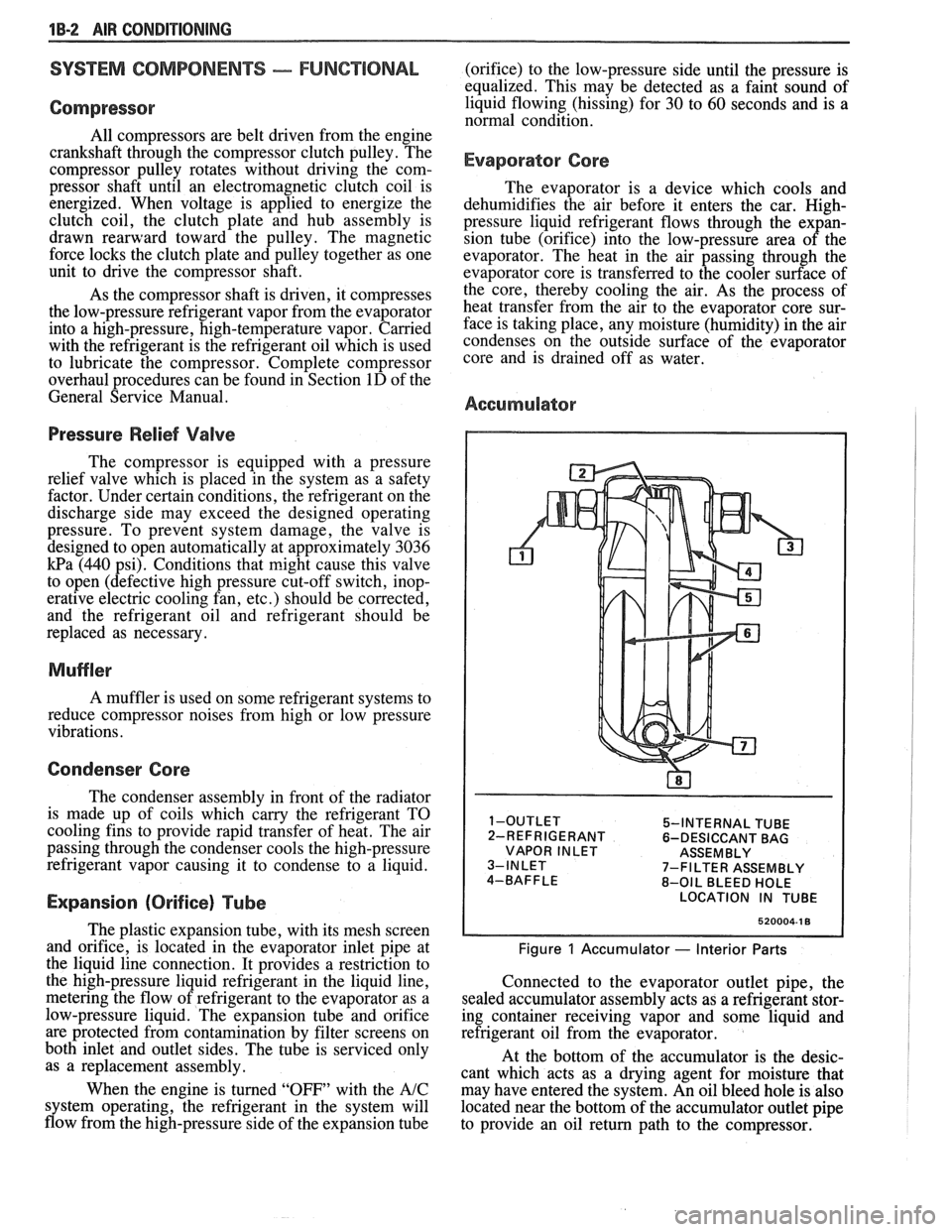
Accumulator
5-INTERNAL TUBE
2-REFRIGERANT 6-DESICCANT BAG
VAPOR INLET ASSEMBLY
7-FILTER ASSEMBLY
8-OIL BLEED HOLE
LOCATION IN TUBE
520004-1 8
Figure 1 Accumulator - Interior Parts
Connected to the evaporator outlet pipe, the
sealed accumulator assembly acts as a refrigerant stor-
ing container receiving vapor and some liquid and
refrigerant oil from the evaporator.
At the bottom of the accumulator is the desic-
cant which acts as a drying agent for moisture that
may have entered the system. An oil bleed hole is also
located near the bottom of the accumulator outlet pipe
to provide an oil return path to the compressor.
Page 46 of 1825
AIR CONDITIONING 1 B-3
A low-side pressure Schrader valve service fit-
ting is located near the top of the accumulator. A
similar Schrader fitting may be provided for mounting
the pressure cycling switch. It is not necessary to dis-
charge the system to replace the switch. The accumu-
lator is serviced only as a replacement assembly.
Heater Core
The heater core heats the air before it enters the
car. Engine coolant is circulated through the core to
heat the outside air passing over the fins of the core.
The core is functional at all times (no water valve) and
may be used to temper conditioned air in
A/C mode,
as well as heat or vent mode.
SYSTEM COMPONENTS --- CON"FOL
Controller
The operation of the A/C system is controlled by
the switches and the lever on the control head. The
compressor clutch and blower are connected electri-
cally to the control head by a wiring harness. The
blower circuit is open in the off mode and air flow is
provided by the four blower speeds available in the
remaining modes. Cooled and dehumidified air is
available in the max, normal, bi-level and defrost
modes.
Temperature is controlled by the position of the
temperature lever on the control head. A cable con-
nects this lever to the temperature door which controls
air flow through the heater core. As the temperature
lever is moved through its range of travel, a sliding
clip on the cable at the temperature valve connection
should assume a position assuring that the temperature
door will seat in both extreme positions. Temperature
door position is independent of mode selection. The
temperature cable attaches to the right side of the air
conditioning module. The temperature door on some
models is controlled electrically, thereby eliminating
the need for the temperature cable.
The electric engine cooling fan on some cars is
not part of the
A/C system; however, the fan is
operational any time the
A/C control is in Max.,
Norm, or Bi-Level modes. Some models provide for
engine cooling fan operation when the controller is in
the defrost mode. This added feature is part of the
A/C
controller function and is aimed at preventing exces-
sive compressor head temperatures. It also allows the
A/C system to function more efficiently. On some
models during road speed (above
35 mph) conditions
when air flow through the condenser coil is adequate
for efficient cooling, the engine cooling fan will be
turned off. The operation of the cooling fan is con-
trolled by the ECM through the cooling fan relay.
Complete wiring diagrams and diagnosis for the
AIC Electrical System are in Section 8A. Section 8A
also contains additional diagnostic information
regarding air flows and vacuum logic.
Vacuum Lines
Vacuum lines are molded to a connector which
is attached to a vacuum control switch on the control
head assembly.
In case of leakage or hose collapse, it will not be
necessary to replace the entire harness assembly.
Replacement can be made by cutting the hose and
inserting a plastic connector. If an entire hose must be
replaced, cut all hoses off at the connector and then
attach hoses directly to the control head vacuum
switch. (NOTE: The Fiero uses an electric motor to
control mode selection. Therefore, it will not have a
vacuum harness.
)
Vacuum Tank
During heavy acceleration, the vacuum supply
from the carburetor drops. A check valve in the vac-
uum tank maintains vacuum so that, under load condi-
tions, vacuum will be available for continuous use.
REWVS AND SWITCHES
High-Pressure Compresssr Gut-OFF Switch
The high-side, high-pressure cut-off switch in
the rear head of the compressor is a protective device
intended to prevent excessive compressor head pres-
sures and reduce the chance of refrigerant escape
through a safety relief valve. Normally closed, this
switch will open the circuit at a high-side pressure of
approximately 2700
kPa (430 psi 9 20 psi) and
reclose the circuit at approximately 1379 kPa (200 psi
9 50 psi).
Lsw-Pressure Cut-On Switch
Compressor protection is provided on some cars
by a low-pressure cut-off switch which will open in
the event of a low-charge condition. This switch can
be located in the liquid line or in the rear head of the
compressor. This switch will also keep the compres-
sor from running during cold weather.
Pressure eyesing Switch
The refrigeration cycle (on and off operation of
the compressor) is controlled by a switch which
senses the low-side pressure as an indicator of evapo-
rator temperature. The pressure cycling switch is the
freeze protection device in the system and senses
refrigerant pressure on the suction side of the system.
This switch is located on a standard Schrader-type
valve low-side fitting. This switch also provides com-
pressor cut-off during cold weather.
Additional compressor protection results from
the operating characteristics of the low-side pressure
cycling system. If a massive discharge occurs or the
orifice tube becomes plugged, low-side pressures
could be insufficient to close the contacts of the pres-
sure switch. In the event of a low charge, insufficient
cooling accompanied by rapid compressor clutch
cycling will be noticed at high air temperatures.
Page 47 of 1825

18-4 AIR CONDITIONING
If replacement of the pressure cycling switch is
necessary, it is important to note that this may be done
without removing the refrigerant charge.
A Schrader-
type valve is located in the pressure switch fitting.
During replacement of the pressure switch, a new
oiled O-ring must be installed and the switch assem-
bled to the specified torque of
6- 13 N*m (5- 10 lb. ft.).
Power Steering Gut-OH, or Anticipate
Switch
Engine idle quality on some cars is maintained
by cutting off the compressor (switch normally
closed) when high power steering loads are imposed.
On other cars the switch (normally open) provides a
signal to the ECM to allow engine control systems to
compensate for high-power steering loads.
Wide-Open Tkroale (WOT) Compressor
Cut-Out
Switch
A switch located on the throttle corltrols of some
carburetor equipped cars opens the circuit to the com-
pressor clutch during full throttle acceleration. The
switch activates a relay that controls the compressor
clutch. During full throttle acceleration
on cars
equipped with TBI or
Em, the TPS sends a signal to
the ECM, thereby controlling the compressor clutch.
Air Conditioning Time Delay Relay
This relay on some cars controls the current to
the entire air conditioning system and provides a short
delay of air conditioning operation upon start-up.
Constant Run Relay
Engine idle quality on some cars is maintained
by a "constant run" system (constant run relay) that
eliminates compressor cycling during engine idle for a
predetermined time after the vehicle has come to rest
from road speed.
If the idle period continues for an
extended time, the
A/C system may return to a con-
ventional C.C.O.T. mode for a short time to prevent
system freeze-up. The
A/C control relay and constant
run relays are both controlled by the Electronic Con-
trol Module (ECM) which determines operating con-
ditions by evaluating input from the distributor
(engine speed), vehicle speed sensor, air sensor and
A/C compressor "on" signal.
5-PRESSURE CYCLING 8-EXPANSION TUBE
SWITCH (ORIFICE)
6-DESSICANT BAG O-LIQUID LINE
7-OIL BLEED HOLE
10-PRESSURE RELIEF
VALVE
@ ee LOW PRESSURE LIQUID HIGH PRESSURE LIQUID LOW PRESURE VAPOR HIGH PRESSURE VAPOR
Figure 2 A/C System - Typical
Page 50 of 1825
AIR GONDlTlONlNG 1B-7
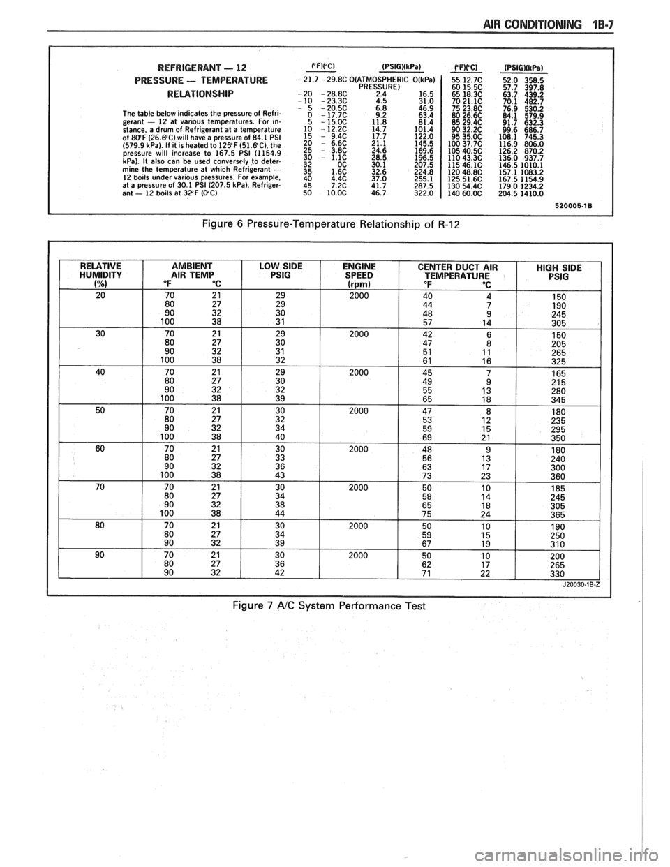
REFRIGERANT - 12
PRESSURE - TEMPERATURE
RELATIONSHIP
The table below indicates the pressure of Refri-
gerant - 12 at various temperatures. For in-
stance, a drum of Refrigerant at a temperature
of
&!OF (26.%C) will have a pressure of 84.1 PSI
(579.9 kPa). If it is heated to 129 F (51.%C), the
pressure will increase to 167.5 PSI (1154.9
kPa). It also can be used conversely to deter-
mine the temperature at which Refrigerant - 12 boils under various pressures. For example,
at a pressure of 30.1 PSI (207.5 kPa), Refriger-
ant - 12 boils at 32F ((PC).
O(ATM0SPHERIC PRESSURE)
2.4
4.5
Figure 7 A/C System Performance Test
Page 55 of 1825
18-12 AIR CONDITIONING
ELEGTRICAWACUUM SYSTEM
DIAGNOSIS
When diagnosing problems in the electrical sys-
tems of the air conditioning system, consult section
8A.
LEAK TESTING THE REFRIGERANT
SYSTEM
Whenever a refrigerant leak is suspected in the
system or a service operation performed which results
in disturbing lines or connections, it is advisable to
test for leaks.
Liquid Leak Detectors
There are a number of locations (fittings,
valves, etc.) on the air conditioning system where a
liquid leak detector solution may be used to pinpoint
refrigerant leaks.
By applying test solution to the area in question
with the swab that is attached to the bottle cap, bub-
bles will form within seconds if there is a leak.
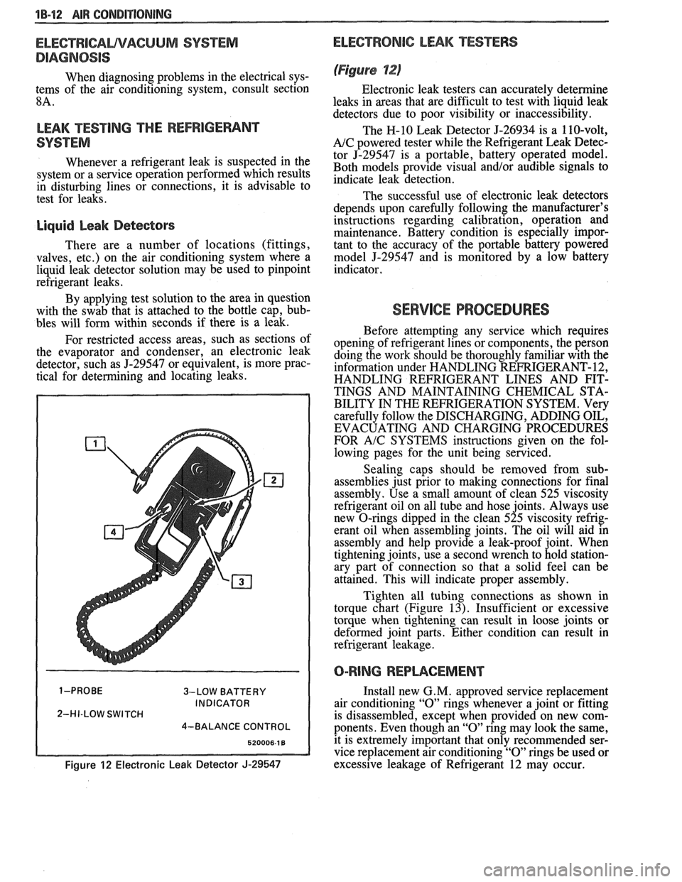
For restricted access areas, such as sections of
the evaporator and condenser, an electronic leak
detector, such as
5-29547 or equivalent, is more prac-
tical for determining and locating leaks.
3-LOW BATTERY
INDICATOR
2-HI-LOW SWITCH
4-BALANCE CONTROL
Figure 12 Electronic Leak Detector J-29547
ELECTRONIC LEAK TESTERS
(Figure 12)
Electronic leak testers can accurately determine
leaks in areas that are difficult to test with liquid leak
detectors due to poor visibility or inaccessibility.
The H-10 Leak Detector 5-26934 is a 110-volt,
A/C powered tester while the Refrigerant Leak Detec-
tor J-29547 is a portable, battery operated model.
Both models provide visual
and/or audible signals to
indicate leak detection.
The successful use of electronic leak detectors
depends upon carefully following the manufacturer's
instructions regarding calibration, operation and
maintenance. Battery condition is especially impor-
tant to the accuracy of the portable battery powered
model
5-29547 and is monitored by a low battery
indicator.
SERVICE PROCEDURES
Before attempting any service which requires
opening of refrigerant lines or components, the person
doing the work should be thoroughly familiar with the
information under HANDLING REFRIGERANT- 12,
HANDLING REFRIGERANT LINES AND FIT-
TINGS AND MAINTAINING CHEMICAL STA-
BILITY IN THE REFRIGERATION SYSTEM. Very
carefully follow the DISCHARGING, ADDING OIL,
EVACUATING AND CHARGING PROCEDURES
FOR
A/C SYSTEMS instructions given on the fol-
lowing pages for the unit being serviced.
Sealing caps should be removed from sub-
assemblies just prior to making connections for final
assembly. Use a small amount of clean 525 viscosity
refrigerant oil on all tube and hose joints. Always use
new O-rings dipped in the clean 525 viscosity refrig-
erant oil when assembling joints. The oil will aid in
assembly and help provide a leak-proof joint. When
tightening joints, use a second wrench to hold station-
ary part of connection so that
a solid feel can be
attained. This will indicate proper assembly.
Tighten all tubing connections as shown in
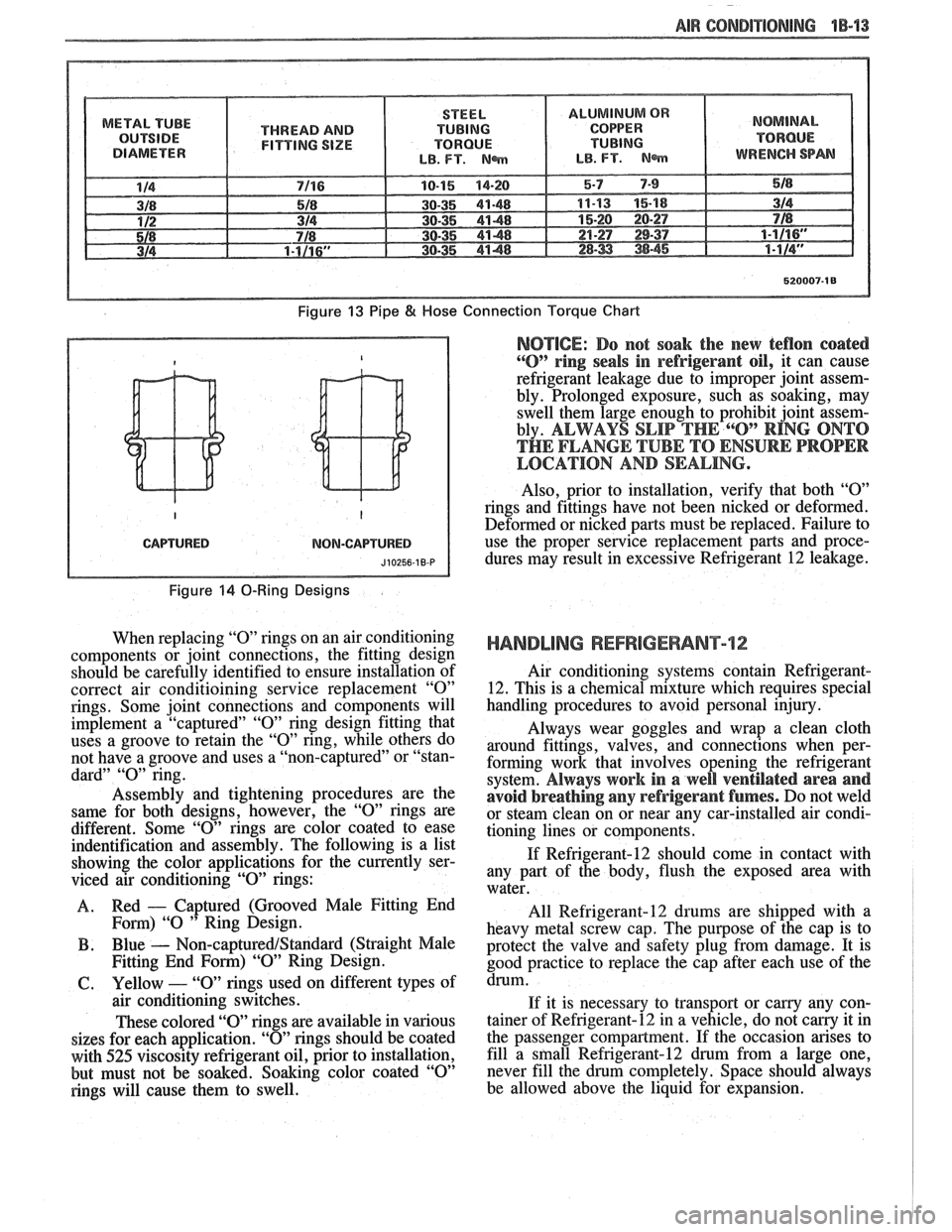
torque chart (Figure
13). Insufficient or excessive
torque when tightening can result in loose joints or
deformed joint parts. Either condition can result in
refrigerant leakage.
O-RING REPWCEMENT
Install new G. M. approved service replacement
air conditioning
"0" rings whenever a joint or fitting
is disassembled, except when provided on new com-
ponents. Even though an
"0" ring may look the same,
it is extremely important that only recommended ser-
vice replacement air conditioning
"0" rings be used or
excessive leakage of Refrigerant 12 may occur.
Page 56 of 1825
-
AIR CONDlTlQNlNG 1B-'13
METAL TUBE
THREAD AND
FITTING SIZE
Figure 13 Pipe 8( Hose
CAPTURED NOM-CAPTURED
Figure 14 0-Ring Designs
When replacing "0" rings on an air conditioning
components or joint connections, the fitting design
should be carefully identified to ensure installation of
correct air conditioining service replacement
"0"
rings. Some joint connections and components will
implement a "captured"
"0" ring design fitting that
uses a groove to retain the
"0" ring, while others do
not have a groove and uses a "non-captured" or "stan-
dard"
"0" ring.
Assembly and tightening procedures are the
same for both designs, however, the
"0" rings are
different. Some
"0" rings are color coated to ease
indentification and assembly. The following is a list
showing the color applications for the currently ser-
viced air conditioning
"0" rings:
A. Red
- Captured
(Grooved Male Fitting End
Fom) "0 " Ring Design.
B . Blue - Non-captured/Standard (Straight Male
Fitting End
Form) "09' Ring Design.
61. Yellow - "0" rings used on different types of
air conditioning switches.
These colored "O" rings are available in various
sizes for each application.
"0" rings should be coated
with
525 viscosity refrigerant oil, prior to installation,
but must not be soaked. Soaking color coated
"0"
rings will cause them to swell.
Connection Torque Chart
NOTICE: Do not soak the new teflon coated
"0" ring seals in refrigerant oil, it can cause
refrigerant leakage due to improper joint assem-
bly. Prolonged exposure, such as soaking, may
swell them large enough to prohibit joint assem-
bly.
ALWAYS SLIP THE 6"O" RING ONTO
THE FLANGE TUBE TO ENSURE PROPER
LOCATION AND SEALING.
Also, prior to installation, verify that both "09'
rings and fittings have not been nicked or deformed.
Deformed or nicked
parts must be replaced. Failure to
use the proper service replacement parts and proce- dures may result in excessive Refrigerant
12 leakage.
HANDLING REFRIGERANT12
Air conditioning systems contain Refrigerant-
12. This is a chemical mixture which requires special
handling procedures to avoid personal injury.
Always wear goggles and wrap a clean cloth
around fittings, valves, and connections when per-
forming work that involves opening the refrigerant
system.
Always work in a well ventilated area and
avoid breathing
any refrigerant fumes. Do not weld
or steam clean on or near any car-installed air condi-
tioning lines or components.
If Refrigerant-12 should come in contact with
any part of the body, flush the exposed area with
water.
All
Refrigerant-12 drums are shipped with a
heavy metal screw cap. The purpose of the cap is to
protect the valve and safety plug from damage. It is
good practice to replace the cap after each use of the
drum.
If it is necessary to transport or carny any con-
tainer of Refrigerant-12 in a vehicle, do not
carry it in
the passenger compartment. If the occasion arises to
fill a
sfnall Refrigerant-12 drum from a large one,
never fill the drum completely. Space should always
be allowed above the liquid for expansion.
Page 57 of 1825
18-14 AIR CONDITIONING
HANDLING OF REFRIGERANT LINES AND
FI-INGS
Tighten all tubing connections as shown in
torque chart (Figure 13). INSUFFICIENT OR
EXCESSIVE TORQUE WHEN TIGHTENING CAN
RESULT IN LOOSE JOINTS OR DEFORMED
JOINT PARTS. Either condition can result in refrig-
erant leakage.
All metal tubing lines should be free of dents or
kinks to prevent loss of system capacity due to line
restriction.
@ The flexible hose lines should never be bent to a
radius of less than four (4) times the diameter of
the hose.
@ The flexible hose lines should never be allowed
to come within a distance of
63.5mm (2-112") of
the exhaust manifold.
@ Flexible hose lines should be inspected regularly
for leaks or brittleness and replaced with new
lines if deterioration or leaking is found.
@ When disconnecting any fitting in the refrigera-
tion system, the system must first be discharged
of all Refrigerant- 12. Proceed very cautiously
regardless of gauge readings. Open very slowly,
keeping face and hands away so that no injury
can occur if there happens to be liquid
Refriger-
ant-12 in the line. If pressure is noticed when
fitting is loosened, allow it to bleed off as
described under DISCHARGING, ADDING
OIL, EVACUATING AND CHARGING PRO-
CEDURES FOR
A/C SYSTEMS.
@ In the event any refrigerant line is opened to the
atmosphere, it should be immediately capped or
taped to prevent entrance of moisture and dirt,
which can cause internal compressor wear or
plugged lines, in the condenser and evaporator
core and expansion (orifice) tubes or compressor
inlet screens.
@ The use of the proper wrenches when making
connections on O-ring fittings is important. The
opposing fitting should always be backed up
with a wrench to prevent distortion of connecting
lines or components. When connecting the flexi-
ble hose connections, it is important that the
swaged fitting and the flare nut, as well as the
coupling to which it is attached, be held at the
same time using three
(3) different wrenches to
prevent turning the fitting and damaging the
ground seat.
@ O-rings and seats must be in perfect condition. A
burr or piece of dirt may cause a refrigerant leak.
When replacing the O-ring, first dip it in clean
525 viscosity refrigeration oil.
MAINTAINING CHEMICAL STABILITY IN
THE
REFRIGERATION SYSTEM
The efficient operation and life of the air condi-
tioning system is dependent upon the chemical stabil-
ity of the refrigeration system. When foreign materials, such as
dirt, air, or moisture, contaminate
the refrigeration system, they will change the stability
of the Refrigerant-12 and 525 viscosity compressor
oil. They will also affect pressure-temperature rela-
tionship, reduce efficient operation and possibly cause
interior corrosion and abnormal wear of moving parts.
The following general practices should be
observed to insure chemical stability in the system:
1. Before disconnecting a refrigerant connection,
wipe away any dirt or oil at and near the connec-
tion to reduce the possibility of dirt entering the
system. Both sides of the connection should be
capped, plugged or taped as soon as possible to
prevent the entry of dirt, foreign material and
moisture.
2. Keep tools clean and dry. This includes the
manifold gauge set and replacement parts.
3. When adding 525 viscosity refrigerant oil (see
ADDING OIL in the DISCHARGING,
ADDING OIL, EVACUATING AND
CHARGING PROCEDURES FOR
AIC SYS-
TEMS, the transfer device and container should
be clean and dry to assure that refrigeration oil
remains as moisture-free as possible.
4. When it is necessary to "open" an
AIC system,
have everything needed ready and handy so that
as little time as possible will be required to per-
form the operation. Do not leave the
AIC system
open any longer than is necessary.
5. Any time the
A/C system has been "opened," it
should be properly evacuated before recharging
with Refrigerant- 12 according to the DIS-
CHARGING, ADDING OIL, EVACUATING
& CHARGING PROCEDURES FOR AIC
SYSTEMS.
All service parts are dehydrated and sealed
prior to shipping. They should remain sealed until just
prior to making connections. All parts should be at
room temperature before uncapping. (This prevents
condensation of moisture from the air entering the
system.) If, for any reason, caps are removed but the
connections are not made, parts should be resealed as
soon as possible.
DISCHARGING, ADDING OIL,
EVACUATING AND CHARGING
PROCEDURES FOR NC SYSTEMS
The refrigerant system may be discharged,
evacuated and charged using air conditioning service
charging station J-23500-01 or equivalent, or the
manifold and gauge set
5-23575-01 and 420ml (14
oz.) disposable cans of Refrigerant-12 (Figure 16).
Charging lines from the charging station or
manifold and gauge set require the use of gauge
adapters to connect to the system service fitting.
A
straight gauge adapter 5-5420 and a 90" angle gauge
adapter
5-9459 are available (see A/C Special Tools).
Always wear goggles and wrap a clean cloth
around fittings and connections when doing work that
Page 58 of 1825
AIR GONDlTlONlNG 1B-15
involves opening the refrigeration system. Always
work in a well ventilated area and avoid breathing any
refrigerant fumes. If liquid refrigerant comes into con-
tact with the eyes, injury may result.
@ Before removing and replacing any of the air
conditioning refrigeration lines or components,
the system must be completely discharged of
Refrigerant- 12.
@ Always use service valve and pressure gauge
sets during evacuation and charging procedures.
@ Always discharge system at low-side service fit-
ting and perform the entire evacuate and charg-
ing procedure through the low-side service
fitting.
@ Do not connect high-pressure line or any line to
the high-side
service fitting during discharging
and charging procedures.
CAUTION: Never remove a gauge line
from its adapter when line is connected
to
AIC system. Always remove the line
adapter from the service
fining to dis-
connect a line. Do not remove charging
hose at gauge set while
anached to ser-
vice low-side
fining. This will result in
complete discharge of system due to
the depressed Schrader valve in
service
low-side fining and may cause personal
injury due to escaping Refrigerant-12.
Discharging the NG System
In replacing any of the air conditioning refriger-
ation components, the system must be completely dis-
charged of Refrigerant- 12.
ALWAYS DISCHARGE SYSTEM AT
LOW-SIDE SERVICE FITTING.
1. With ignition turned "OFF," remove protective
cap from LOW-SIDE service fitting (on most
models) on Accumulator and connect charging
station
J-23500-01 or equivalent gauge set. If
charging station J-23500-01 or equivalent is not
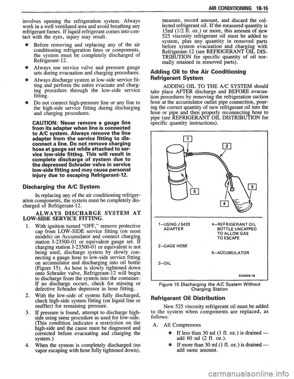
being used, discharge system by slowly con-
necting a gauge hose to low-side
sewice fitting
on accumulator and discharging into oil bottle
(Figure 15). As hose is slowly tightened down
onto Schrader valve, Refrigerant-12 will begin
to discharge from the system into the container.
If no discharge occurs, check for missing or
defective Schrader depressor in hose fitting.
2. With the low-side of system fully discharged,
check high-side system fitting (on liquid line or
muffler) for remaining pressure.
3. If pressure is found, attempt to discharge high-
side using same procedure as used for low-side.
(This condition indicates a restriction on the
high-side and the cause must be diagnosed and
corrected before evacuating and charging the
system.)
4. When the system is completely discharged (no
vapor escaping with hose fully tightened down), measure, record
amount, and discard the col-
lected refrigerant oil. If the measured quantity is
15ml (112 fl. 02.) or more, this amount of new
525 viscosity refrigerant oil must be added to system, plus any quantity in removed parts
before system evacuation and charging with
Refrigerant-12 (see REFRIGERANT OIL DIS-
TRIBUTION for specific quantity of oil nor-
mally retained in removed parts).
Adding Oil to the Air Conditioning
Refrigerant System
ADDING OIL TO THE A/C SYSTEM should
take place AFTER discharge and BEFORE evacua-
tion procedures by removing the refrigeration suction
hose at the accumulator outlet pipe connection, pour-
ing the correct quantity of new refrigerant oil into the
hose or pipe and then properly reconnecting hose to
pipe (see REFRIGERANT OIL DISTRIBUTION for
specific quantity instructions).
1-USING J 5420 4-REFRIGERANT OIL BOTTLE UNCAPPED
TO ALLOW GAS
TO ESCAPE
2-GAGE HOSE 5-ACCUMULATOR
Figure 15 Discharging the A/C System Without
Charging Station
Refrigerant Oil Distribution
New 525 viscosity refrigerant oil must be added
to the system when components are replaced, as
follows:
A. All Compressors
@ If less than 30 ml(1 fl. oz.) is drained -
add 60 ml (2 fl. oz.).
@ If more than 30 ml(1 fl. oz.) is drained --
add same amount.