1988 PONTIAC FIERO oil
[x] Cancel search: oilPage 59 of 1825
"18-16 AIR CONDITIONING
B . Accumulator dehydrator
@ Add 105 ml (3.5 fl. 02.) to new
accumulator
C. Evaporator
@ Add 90 ml (3 fl. oz.) oil
D. Condenser
@ Add 30 ml (1 fl. 02.) oil
Refrigerant oil loss due to a large leak
If the refrigerant charge is aburptly lost due to a
large refrigerant leak, approximately 90
ml (3 fl. oz.)
of refrigerant oil will be
carried out of the system sus-
pended in the refrigerant. Any failure that caused an
abrupt refrigerant discharge will experience this oil
loss. Failures that allow the refrigerant to seep or
bleed off over time do not experience this oil loss.
Upon replacement of a component which
caused a large refrigerant leak, add 90 ml(3
fl. oz.) of
new 525 viscosity refrigerant oil plus the required
amount of oil for the particular component (as out-
lined above).
Add the oil directly to the replaced component if
possible. If the oil cannot easily be added to the
replaced part, add the oil to the accumulator.
Evacuating and Charging the A/C System
If the system has been opened for any repair, or
the Refrigerant-12 charge lost, the system must be
evacuated prior to charging.
Evacuating and charging is a combined proce-
dure, and all gauge lines must be purged with R-12
prior to charging.
There are three evacuate and charge procedures.
1.
J 23500-01 Charging Station Method
2. Disposable Can Method 3. Drum Method
NOTICE: Under no circumstances should alco-
hol be used in the system in an attempt to remove
moisture. Damage to the system components
could occur.
Gauge Calibration
Prior to evacuation, check the low-pressure
gauge for proper calibration and determine if vacuum
system is operating properly.
With the gauge disconnected from the refrigera-
tion system, be sure that the pointer indicates to the
center of
"0". Lightly tap gauge a few times to be sure
pointer is not sticking. If necessary, calibrate as
follows:
1. Remove cover from gauge.
2. Holding gauge pointer adjusting screw firmly
with one hand, carefully force pointer in the
proper direction to position pointer at the
"0"
position. Tap gauge a few times to be sure
pointer is not sticking. Replace gauge cover.
Vacuum System Check
Before connecting vacuum pump to the A/C
system, run pump connected to the low-pressure
gauge to determine the vacuum pump capability. If
the vacuum system is unable to reach
7 1 1.2-736.6mm
(28"-29") or more vacuum, the system should be
checked for leaks. If no leaks are found, the vacuum
pump may require repair.
5-23580-81 OR EQUIVALENT CHARGING
STATION METHOD.
Follow charging instructions provided with the
5-23500-01 Charging Station or equivalent in use with
the following exceptions:
1. Do
not connect the high-pressure line to the air
conditioning system.
2. Keep the high-pressure valve on the charging
station closed at all times.
3.
Perform the entire evacuate and charge proce-
dure through the accumulator low-side pressure service fitting.
4. Following these procedures will prevent acci-
dental high-side vehicle system pressure being
subjected to the charging station in the event an
error is made in valve sequence during compres-
sor operation to pull in the Refrigerant-12
charge.
DISPOSABLE CAN OR REFRIGERANT
DRUM METHOD.
If the Refrigerant-12 drum is used, place it on a
scale and note the total weight before charging. Watch
the scale during charging to determine the amount of
R-12 used.
If disposable
420ml (14 ounce) R-12 cans are
used, close the tapping valve and then attach
can(s)
following instructions included with the tapping valve
or tapping manifold adapter.
1. Connect manifold gauge set 5-23575-01 as fol-
lows. Also see Figure 16.
a. Eow-pressure gauge to accumulator fit-
ting.
b. Gauge set center hosk to Refrigerant-12
source.
c. High-pressure gauge to vacuum pump.
2. To begin evacuation of the
A/C system with
manifold gauge set and vacuum pump as illus-
trated in Figure 16, slowly open
high- and low-
side gauge valves and begin vacuum pump oper-
ation. Pump the system until the low-side gauge
reaches 7 1
1.2-736.6mm (28"-29") vacuum.
Note that in all evacuation procedures, the spec-
ification of 7 1
1.2-736.6mm (28"-29") vacuum is
used. This specification can only be reached at
or near sea level. For each
304.8m (1,000 feet)
above sea level, specification should be lowered
by one inch vacuum. At
1524m (5,000 feet)
elevation, only
584.2-609.6mm (23"-24") of
vacuum is required.
Page 61 of 1825
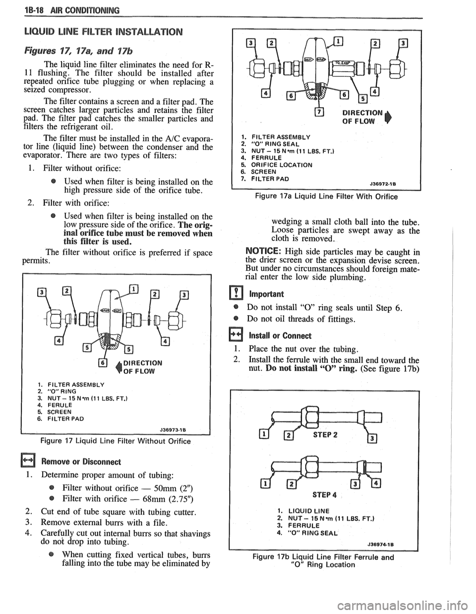
LlOQllD LiNE FILTER INSTALLATION
Figures 'IT", 17% and 17b
The liquid line filter eliminates the need for R-
11 flushing. The filter should be installed after
repeated orifice tube plugging or when replacing a
seized compressor.
The filter contains a screen and a filter pad. The
screen catches larger particles and retains the filter
pad. The filter pad catches the smaller particles and filters the refrigerant oil.
The filter must be installed in the
A/C evapora-
tor line (liquid line) between the condenser and the
evaporator. There are two types of filters:
@ DIRECTION
OF FLOW
1. FILTER ASSEMBLY 2. "0" RlNG SEAL 3. NUT- 15N.m (11 LBS. FT.) 4. FERRULE
1. Filter without orifice: 5. ORIFICE LOCATION
@ Used when filter is being installed on the 7. FILTER PAD
high pressure side of the orifice tube. Figure 17a Liquid Line Filter With Orifice
2. Filter with orifice:
@ Used when filter is being installed on the
low pressure side of the orifice.
The orig-
inal orifice tube must be removed when
this filter is used.
The filter without orifice is preferred if space
permits.
DIRECTION
OF FLOW
1. FILTER ASSEMBLY 2. "0"RING 3. NUT - 15 Nem (1 1 LBS. FT.) 4. FERULE
5. SCREEN
6. FILTER PAD
Figure 17 Liquid Line Filter Without Orifice
Remove or Disconnect
1. Determine proper amount of tubing:
@ Filter without orifice - 50mm (2")
@ Filter with orifice - 68mm (2.95")
2. Cut end of tube square with tubing cutter
3. Remove external burrs with a file.
4. Carefully cut out internal burrs so that shavings
do not drop into tubing. wedging a small cloth ball
into the tube.
Loose particles are swept away as the
cloth is removed.
NOTICE: High side particles may be caught in
the drier screen or the expansion devise screen.
But under no circumstances should foreign mate-
rial enter the low side plumbing.
m Important
@ Do not install "0 ring seals until Step 6.
@ Do not oil threads of fittings.
a Install or Connect
1. Place the nut over the tubing. -
2. Install the ferrule with the small end toward the
nut.
Do not install ""0' ring. (See figure 17b)
STEP 4
1. LIQUID LINE 2. NUT - 15 N m (1 1 LBS. FT.) 3. FERRULE 4. "0" RlNG SEAL
@ When cutting fixed vertical tubes, burrs Figure 17b Liquid Line Filter Ferrule and falling into the tube may be eliminated by "0" Ring Location
Page 62 of 1825
AIR CONDITIONING 18-19
3. Push the tube into the fitting, bottoming it out.
Tighten
@ Torque nut to 15 Nam (11 lbs. ft.).
4. Dissasemble the joint.
5. Lubricate the
"0" ring with clean 525 viscosity
refrigerant oil.
6. Install the
"0" ring
on the tube. (See figure 17b)
7. Reassemble joint.
Tighten
@ Torque nut to 15 Nem (11 lbs. ft.).
8. Evacuate, charge, and leak test the system.
EXPANSlON "%BE (ORIFICE) SERVlCE
Remove or Disconnect
1. Discharge system.
2. Loosen fitting
at liquid line to evaporator inlet
pipe and remove tube carefully with needle
nosed pliers or Tool
5-26549-C or equivalent.
Install or Connect
1. Install
new orifice tube with shorter screen end
in first.
2. Install
liquid line and torque to proper
specification.
3. Evacuate and charge system.
In the event that difficulty is encountered during
the removal of a restricted or plugged expansion tube
(orifice tube), the following procedure is recom-
mended:
1. Remove
as much of any impacted residue as
possible.
2. Carefully apply heat with heat gun (hair drier,
epoxy drier or equivalent) approximately
114
inch from dimples on inlet pipe. Do not over-
heat pipe.
NOTICE: If the system has a pressure switch
near the orifice tube location, it should be
removed prior to heating the pipe to avoid dam-
age to switch.
3. While applying heat, use orifice removal tool
5-26549-C to grip the orifice tube. Use a turning
motion along with a push-pull motion to loosen
to the impacted orifice tube and remove it.
4. Swab inside of evaporator inlet pipe with R-11.
5, Add
1 oz. of 525 viscosity refrigerant oil to
system.
6. Lubricate new orifice tube and O-ring with 525'
viscosity refrigerant oil and insert into inlet
pipe. Install in proper direction (smaller screen
first).
ACCUMULATOR ASSEMBLY SERVICE
The accumulator assembly for the refrigerant
system has a service replacement which includes two
(2) O-rings (for the inlet and outlet connections). The
desiccant within the shell is NOT serviced separately
- it is part of the sealed accumulator assembly. See
REFRIGERANT OIL DISTRIBUTION for condi-
tions when the accumulator must be removed from the
vehicle to measure the amount of oil present inside the
accumulator.
The accumulator assembly should ONLY be
replaced when:
1. A physical perforation to the accumulator is
found, resulting in a leak.
2. If the system is open to air for an extended
period of time (due to a front-end collision,
removed parts, ect.). The desiccant bag will be
saturated with moisture.
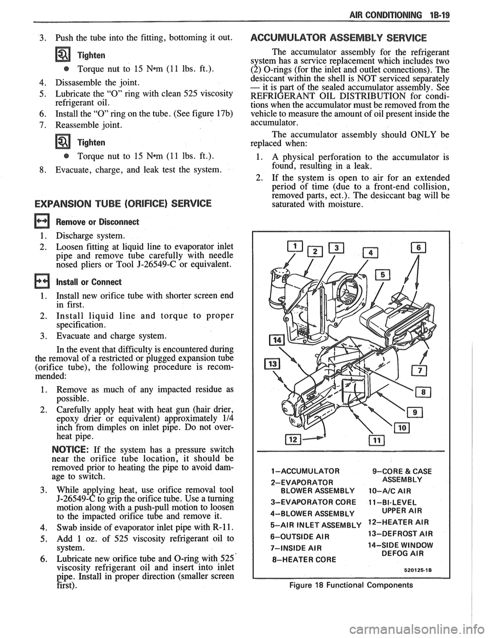
1 -ACCUMULATOR 9-CORE & CASE
2-EVAPORATOR BLOWER ASSEMBLY
10-A/C AIR
3-EVAPORATOR CORE 11-BI-LEVEL
4-BLOWER ASSEMBLY 5-AIR INLET ASSEMBLY
'IR
6-OUTSIDE AIR 13-DEFROST
AIR
7-INSIDE
AIR 14-SIDE WINDOW
DEFOG AIR
8-HEATER CORE
Figure 18 Functional Components
Page 66 of 1825
AIR CONDITIONING "18-23
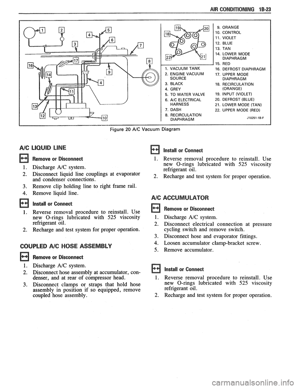
10. CONTROL
14. LOWER MODE
DIAPHRAGM
16. DEFROST DIAPHRAGM
17. UPPER MODE
DIAPHRAGM
18. RECIRCULATION
5. TO WATER VALVE 19. lfVPUT (VIOLET)
6. A/C ELECTRICAL 20. DEFROST (BLUE)
21. LOWER MODE (TAN)
22. UPPER MODE (RED)
8. RECIRCULATION
DIAPHRAGM J~OZ~~-IB-F
Figure 20 AIC Vacuum Diagram
NG LlCbUlB LINE
Remove or Disconnect
1. Discharge A!C system.
2. Disconnect liquid line couplings at evaporator
and condenser connections.
3. Remove clip holding line to right frame rail.
4. Remove liquid line.
lnstall or Conne&
1. Reverse removal procedure to reinstall. Use
new O-rings lubricated with
525 viscosity
refrigerant oil.
2. Recharge and test system for proper operation.
COUPLED NC HOSE ASSEMBLY
Remove or Disconne&
lnstall or Conne&
1. Reverse removal procedure to reinstall. Use
new O-rings lubricated with
525 viscosity
refrigerant oil.
2. Recharge and test system for proper operation.
Remove or Disconnect
1. Discharge A!C system.
2. Disconnect electrical connection at pressure
cycling switch and remove switch.
3. Disconnect hose and evaporator fittings.
4. Loosen accumulator clamp-bracket screw.
5. Remove accumulator.
1. Discharge
NC system.
2. Disconnect hose assembly at accumulator, con- Install or Connect
denser, and at rear of c6mpressor head. 1. Reverse removal procedure to reinstall. Use
3. Disconnect clamps or straps that hold hose new
O-rings lubricated with 525 viscosity
assembly in position if so equipped, remove refrigerant
oil.
coupled hose assembly.
2. Recharge and test system for proper operation.
Page 67 of 1825
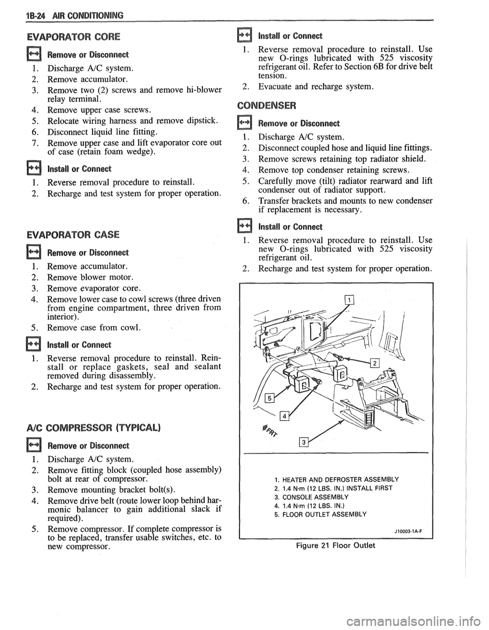
1B-24 AIR CONDPTIBNING
EVAPORATOR CORE
Remove QP Disconnect
1. Discharge A/C system.
2. Remove accumulator.
3. Remove two (2) screws and remove hi-blower
relay terminal.
4. Remove upper case screws.
5. Relocate wiring harness and remove dipstick.
6. Disconnect liquid line fitting.
7. Remove upper case and lift evaporator core out
of case (retain foam wedge).
Install or Connect
1. Reverse removal procedure to reinstall.
2. Recharge and test system for proper operation.
EVAPBRAWORCASE
Remove or Disconnect
1. Remove accumulator.
2. Remove blower motor.
3. Remove evaporator core.
Remove lower case to cowl screws (three driven from engine compartment, three driven from
interior).
Remove case from cowl.
Install or Connect
Reverse removal procedure to reinstall. Rein-
stall or replace gaskets, seal and sealant
removed during disassembly.
Recharge and test system for proper operation.
NG COMPRESSOR (TYPICAL)
Remove or Disconnect
1. Discharge A/C system.
2. Remove fitting block (coupled hose assembly)
bolt at rear of compressor.
3. Remove mounting bracket bolt(s) .
4. Remove drive belt (route lower loop behind har-
monic balancer to gain additional slack if
required).
5. Remove compressor. If complete compressor is
to be replaced, transfer usable switches, etc. to
new compressor.
Install or Connect
1. Reverse removal
procedure to reinstall. Use
new O-rings lubricated with
525 viscosity
refrigerant oil. Refer to Section
6B for drive belt
tension.
2. Evacuate and recharge system.
CONDENSER
a Remove or Disconnect
1. Discharge A/C system.
2. Disconnect coupled hose and liquid line fittings.
3, Remove screws retaining top radiator shield.
4. Remove top condenser retaining screws.
5. Carefully move (tilt) radiator rearward and lift
condenser out of radiator support.
6. Transfer brackets and mounts to new condenser
if replacement is necessary.
Install or Connect
1. Reverse removal procedure to reinstall. Use
new O-rings lubricated with
525 viscosity
refrigerant oil.
2. Recharge and test system for proper operation.
1. HEATER AND DEFROSTER ASSEMBLY
2. 1.4
N.m (12 LBS. IN.) INSTALL FIRST
3. CONSOLE ASSEMBLY
4.
1.4 Narn (12 LBS. IN.)
5. FLOOR OUTLET ASSEMBLY
Figure 21 Floor Outlet
Page 78 of 1825
AIR CONDITIONING 1B-35
I
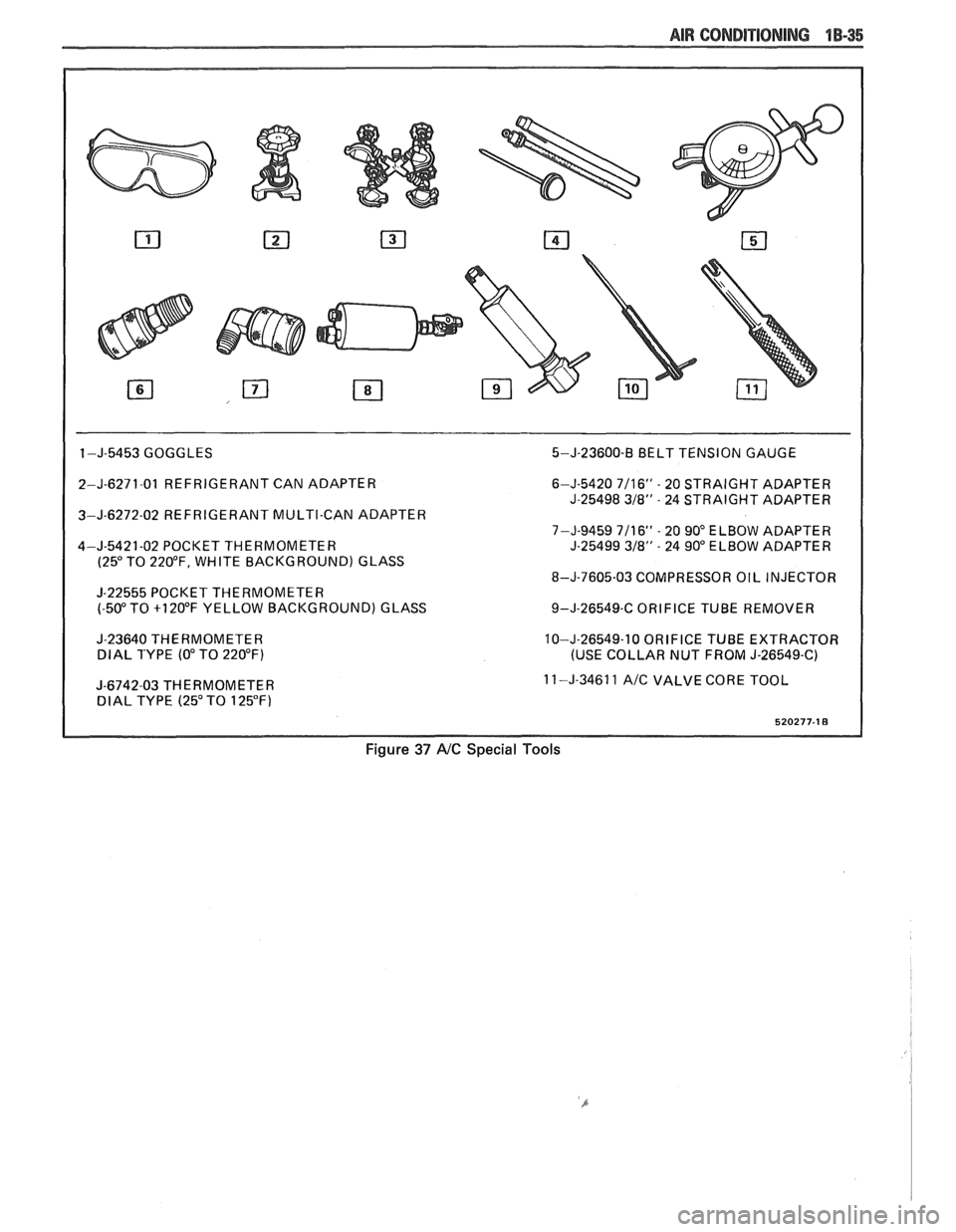
1 -J-5453 GOGGLES 5-J-23600-B BELT TENSION GAUGE
2-J-6271-01 REFRIGERANT CAN ADAPTER
3-J-6272-02 REFRIGERANT MULTI-CAN ADAPTER
4-J-5421-02 POCKET THERMOMETER
(25" TO 220°F, WHITE BACKGROUND) GLASS
J-22555 POCKET THERMOMETER
(-50" TO +I 20°F YELLOW BACKGROUND) GLASS
J-23640 THERMOMETER
DlAL TYPE (0" TO 220°F)
I
J-6742-03 THERMOMETER DlAL TYPE (25" TO 125°F) 6-J-5420
7/16" - 20
STRAIGHT ADAPTER
J-25498
318" - 24 STRAIGHT ADAPTER
7-J-9459 7/16"
- 20 90" ELBOW ADAPTER
J-25499 318" - 24 90" ELBOW ADAPTER
8-J-7605-03 COMPRESSOR OIL INJECTOR
9-J-26549-C ORIFICE TUBE REMOVER
10-J-26549-10 ORIFICE TUBE EXTRACTOR
(USE COLLAR NUT FROM J-26549-C)
11 -J-34611
A/C VALVE CORE TOOL
Figure 37 AIC Special Tools
Page 80 of 1825
W-4 AIR CONDITIONING COMPRESSOR OVERHAUL 1 Dl-l
SECTION 1 Dl
R COND NG COMPRESSOR
OVERHAUL
For Compressor REMOVAL AND INSTALLATION, see Air Conditioning Section 1B. For
DISCHARGING, ADDING OIL, EVACUATING AND CHARGING PROCEDURES FOR
A/C
SYSTEMS, see Air Conditioning Section 1B.
CONTENTS
General Description ............................... 1D1-1
Service Procedures .................................. 1D1-4
Minor Repair Procedures ....................... 1D1-4
Clutch Plate and Hub Assembly ............... 1D1-4
Clutch Rotor and Bearing: Four-Pole
Clutch
..................................................... 1D1-5
Clutch Rotor and Bearing: Six-Pole
Clutch
.......................... ... ....................... 1 D 1-7
Clutch Coil and Pulley Rim ...................... 1 D 1 - 10
Major Repair Procedures ....................... 1D1-12
Shaft Seal .................................................. 1Dl-12
Seal Leak Detection ........................... .... 1D1-12
Replacement (On Car) ........................... 1 D 1- 12
Replacement (Off Car)
........................... 1 D 1 - 13
Pressure Relief Valve
................................. 1 D 1 - 13
Nigh Pressure Cut-Off Switch
................... 1 D 1 - 13
Front Head and 0-Ring
............................ 1 D 1 - 14
Thrust and Belleville Washers
................... 1 D 1 - 16
Main Bearing
.............................................. 1 D 1- 16
Shell and 0-Ring
....................................... 1D 1- 17
Discharge Valve Plate and Retainer
......... 1 D 1 - 18
Cylinder and Shaft Assembly
.................... 1 D 1 - 19
Leak Testing (External and Internal)
........ 1D1- 19
Special Tools ..................................... ... .. 1D1-21
GENERAL DESCRIPTION
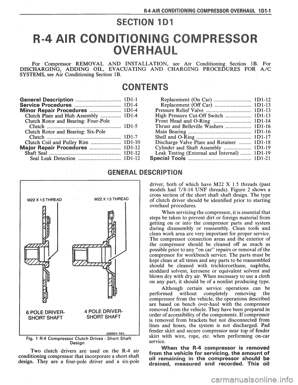
M22 X 1.5 THREAD M22 X 1.5 THREAD
6 POLE DRIVER- 4 POLE DRIVER-
SHORT SHAFT SHORT SHAFT
J20001.1 Dl
Fig. 1 R-4 Compressor Clutch Drives - Short Shaft
Desian
driver, both of which have M22 X 1.5 threads (past
models had 7/8-14
UNF threads). Figure 2 shows a
cross section of the short shaft shaft design. The type
of clutch driver should be identified prior to starting
overhaul procedures.
When servicing the compressor, it is essential that
steps be taken to prevent dirt or foreign material from
getting on or into the compressor parts and system
during disassembly or reassembly. Clean tools and
clean work area are very important for proper service.
The compressor connection areas and the exterior of
the compressor should be cleaned off as much as
possible prior to any "on car" repairs or removal of the
compressor for workbench service. The parts must be
kept clean at all times and any parts to be reassembled
should be cleaned with trichloroethane, naphtha,
stoddard solvent, kerosene or equivalent solvent and
blown dry with dry air. When necessary to use a cloth
on any part, it should be of a nonlint producing type.
Although certain service operations can be
performed without completely removing the
compressor from the vehicle, the operations described
are based on bench over-haul with the compressor
removed from the vehicle. They have been prepared in
order of accessibility of the components. If compressor
is removed from brackets but not disconnected from
lines and hoses, the system is not discharged. Pad
fender skirt and secure compressor near top of fender
skirt with wire, rope,
etc, when performing on-car
service.
., When the R-4 compressor is removed Two 'lutch drivers are wed On the R-4 air from the vehicle for servicing, the amount of conditioning compressor that incorporate a short shaft oil remaining in the should be design. They are a four-pole driver and a six-pole drained, measured and recorded. This oil
Page 81 of 1825
1 Dl-2 R-4 AIR CONDITIONING COMP
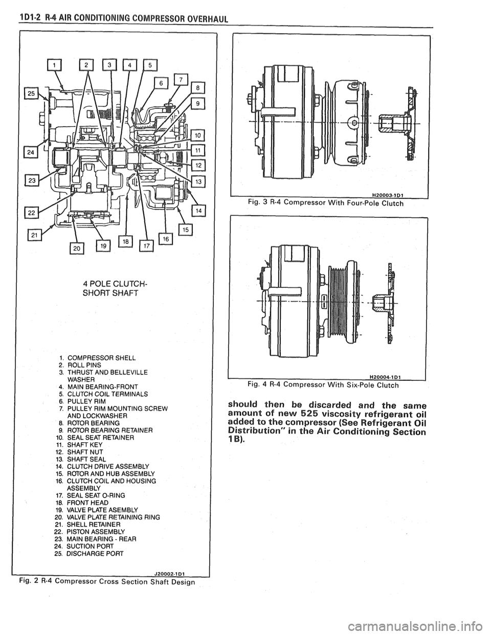
4 POLE CLUTCH-
SHORT SHAFT
1. COMPRESSOR SHELL 2. ROLL PINS 3. THRUST AND BELLEVILLE WASHER 4. MAlN BEARING-FRONT 5. CLUTCH COlL TERMINALS 6. PULLEY RIM 7. PULLEY RIM MOUNTING SCREW
AND LOCKWASHER
8. RmOR BEARING 9. ROTOR BEARING RETAINER
10. SEAL SEAT RETAINER
11. SHAFT KEY 12. SHAFT NUT 13. SHAFT SEAL 14. CLUTCH DRIVE ASSEMBLY 15. ROTOR AND HUB ASSEMBLY 16. CLUTCH COlL AND HOUSING
ASSEMBLY
17. SEAL SEAT O-RING 18. FRONT HEAD 19. VALVE PLATE ASEMBLY
20. VALVE PLATE RETAINING RING
21. SHELL RETAINER 22. PISTON ASSEMBLY 23. MAlN BEARING - REAR 24. SUCTION PORT
25. DISCHARGE PORT
Fig. 4 R-4 Compressor With Six-Pole Clutch
should then be discarded and the same
amount of new
525 viscosity refrigerant oil
added to the compressor (See Refrigerant Oil
Distribution" in
the Air Conditioning Section
1 B).
Fig. 2 R-4 Compressor Cross Section Shaft Design