1988 PONTIAC FIERO oil
[x] Cancel search: oilPage 103 of 1825
2B-2 BUMPERS
REAR BUMPER FASCIA
Removal
Place a jack stand under fascia before removing
bolts to prevent it from dropping down when fascia
attaching bolts are removed. Fascia will pivot on the
opposite end when one end is disconnected. Do not
rotate energy absorber any more than necessary to
align mounting holes.
1. Remove fascia attaching bolts and fascia to
fender attaching screws on right and left side, and
remove fascia and spacers.
2. If energy absorber is to be replaced, remove the
bolts and nuts from the front of the unit and the
nut from the stud at the rear. The stud at the rear
of the absorber is attached to a bracket in the
frame. Remove the bolt holding this bracket in
the frame to remove the absorber.
Installation
1. Install energy absorber if removed.
2. Support fascia during installation to prevent
rotation of energy absorbers.
3. Install spacers and bolts at fascia to energy
absorber brackets.
4. Install fascia to fender attaching screws.
5. Check for proper clearance.
6. If adjustment is required to align the fascia, use
shims as necessary. Vertical and lateral
adjustment can be made at slots in fascia and
absorber brackets. Torque all bolts and nuts. (See
Specifications.)
FRONT BUMPER
Removal
1. Remove
front end fascia as shown in Section 2C.
2. Remove bumper barlenergy absorber assembly
from body.
3. If energy absorber must be replaced, drill out pop
rivets, and install new absorber with nuts, bolts,
and locking washers.
4. To install, reverse above procedure.
REAR BUMPER
Removal
1. Remove left hand rear quarter trim panel.
2. Remove right hand rear quataer trim panel.
3. Remove spare tire assembly.
4. Remove rear center trim panel.
5. Remove right tail light assembly.
6. Remove left tail light assembly.
7. Remove tail light center piece.
8. Remove bumper cover lower retainers.
9. Remove right-side bumper cover fasteners from
inside of compartment.
10. Remove left side bumper cover fasteners from
inside of compartment.
11. Remove bumper cover upper retainers.
12. Remove cover.
13. To dissasemble impact bar, proceed as follows:
a. Remove bolts attataching impact bar to
rear end panel.
b. Remove rivets retaining pad to impact
bar.
14. To install, reverse above procedure.
BUMPER ENERGY ABSORBING UNITS
The absorbing capability for both front and rear
bumper systems is achieved through two energy
absorbing devices in each bumper. These units convert
the energy of an impact into heat and restoration. The
energy absorbing device consists of two main
subassemblies: the piston tube assembly and the
cylinder tube assembly. The piston tube assembly is
filled with an inert gas under pressure and consists of
a bumper bracket, piston tube, orifice, seal, piston seal,
piston, and stop-ring. The cylinder tube assembly is
filled with a hydraulic fluid and consists of a frame
bracket, cylinder tube, mounting stud, and metering
pin.
Upon impact, as the energy absorber is collapsed,
the hydraulic fluid in the cylinder tube is forced into
the piston tube through the orifice. The metering pin
controls the rate at which this fluid passes from the
cylinder tube through the orifice and into the piston
tube. This controlled passage of fluid provides the
energy absorbing action.
The hydraulic fluid that is forced from the
cylinder tube into the piston tube displaces the floating
piston, compressing the gas behind the floating piston.
After impact, the pressure of the compressed gas
behind the floating piston forces the hydraulic fluid
back into the cylinder tube assembly, extending the
unit to its normal position.
Some front and rear bumpers (J and
F Models)
use a plastic honeycomb pad energy absorber (except
J wagon rear bumper). This energy absorber will
compress on impact, and both the energy absorber and
the urethane fascia will return to their original shape.
The energy absorber pad has no moving parts.
The J wagon rear bumper system uses a hydraulic
energy absorbing unit, more commonly known as a
"minisorber".
TESTING FRONT OR REAR ENERGY
ABSORBER OPERATION
The right and left energy absorbing devices are to
be diagnosed separately. The following checks are to be
made on each unit:
1. Leakage
Some oil wetting may be visible due to the grease
packed in the crimp recess. Therefore, a stain or trace
of oil on the piston tube near the crimp is normal.
However, if oil is dripping continuously from the crimp
or the stud end of the unit, a leak is indicated and the
unit should be replaced.
Page 109 of 1825
26-2 CHASSIS SHEET METAL
TO RAISE OR LOWER THE FRONT comers
for proper alignment, proceed as follows:
1. Close hood firmly.
2. Determine the amount of adjustment necessary.
3. Open hood.
4. Raise or lower the adjustable hood bumpers as
required.
FORE AND APT adjustment can be accom-
plished as follows:
1. Loosen hinge to fender attaching screws.
Remove or Disconnect
Open hood.
Scribe line on hood inner panel and fender panel
to indicate original hinge position.
Block hood on side where hinge is to be
removed.
Prop hood open.
Remove hinge-to-hood attaching screws and
hinge-to-fender attaching screws.
Carefully remove hinge and strut assembly.
- -
2. Reposition hinge assembly. install or Conned 3. Tighten hinge to fender attaching screws to
specifications. 1. Mount new hinge on fender using scribed line
4. If necessary, repeat procedure on opposite side for location,
and tighten attaching screws.
of hood. 2.
Position hinge to hood using scribed line for
location, install attaching screws and tighten.
3. Carefully close hood and check for proper
- - alignment.
4. If hood is misaligned, measure amount of
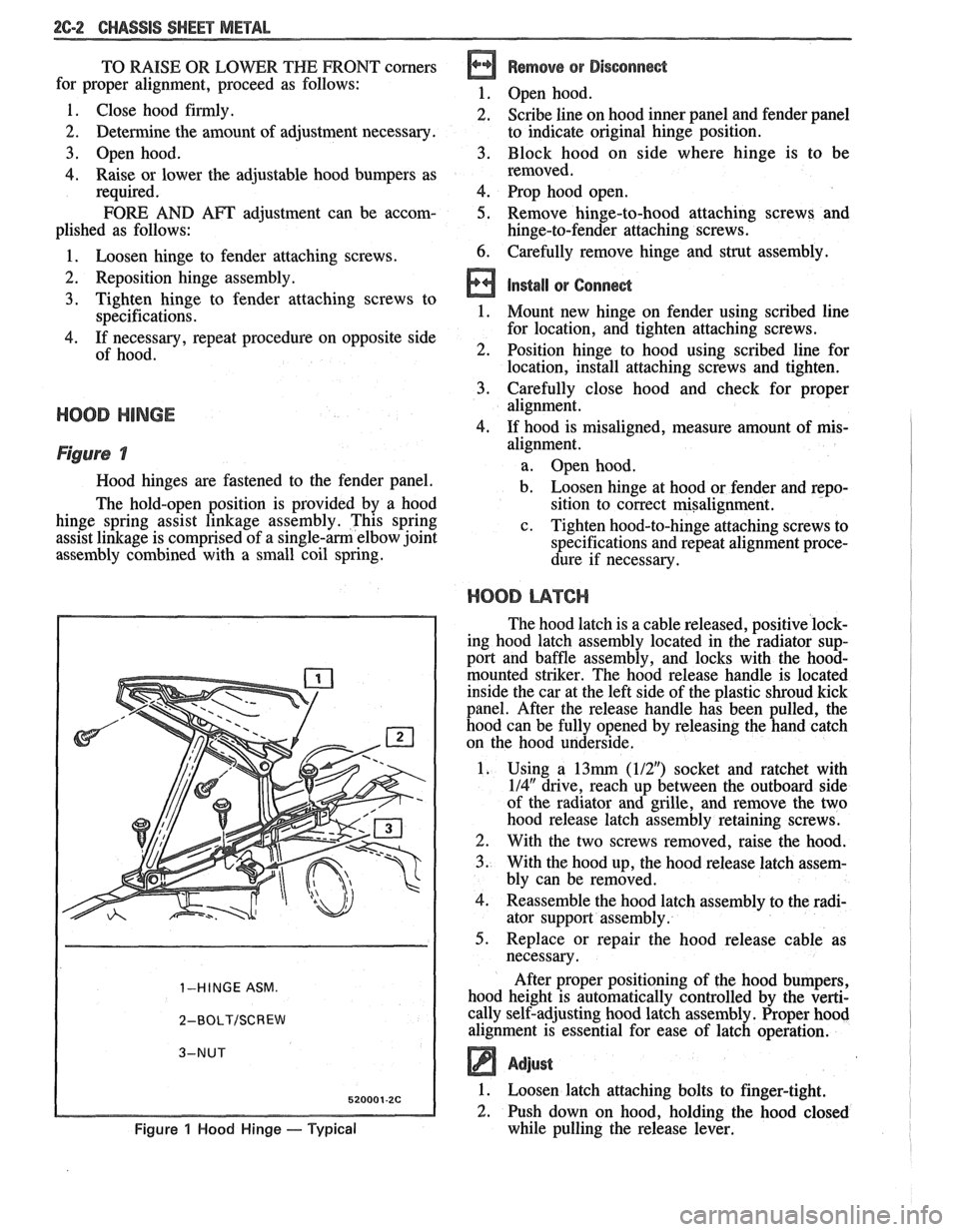
mis-
Figure 7
Hood hinges are fastened to the fender panel.
The hold-open position is provided by a hood
hinge spring assist linkage assembly. This spring
assist linkage is comprised of a
single-am elbow joint
assembly combined with a small coil spring.
1-HINGE ASM.
2-BOLT/SCREW
Figure 1 Hood Hinge - Typical
alignment.
a. Open hood.
b. Loosen hinge at hood or fender and repo-
sition to correct misalignment.
c. Tighten hood-to-hinge attaching screws to
specifications and repeat alignment proce-
dure if necessary.
HOOD L14TCI-I
The hood latch is a cable released, positive lock-
ing hood latch assembly located in the radiator sup-
port and baffle assembly, and locks with the
hood-
mounted striker. The hood release handle is located
inside the car at the left side of the plastic shroud kick
panel. After the release handle has been pulled, the
hood can be fully opened by releasing the hand catch
on the hood underside.
1. Using a
13mrn (112") socket and ratchet with
114" drive, reach up between the outboard side
of the radiator and grille, and remove the two
hood release latch assembly retaining screws.
2. With the two screws removed, raise the hood.
3. With the hood up, the hood release latch assem-
bly can be removed.
4. Reassemble the hood latch assembly to the radi-
ator support assembly.
5. Replace or repair the hood release cable as
necessary.
After proper positioning of the hood bumpers,
hood height is automatically controlled by the verti-
cally self-adjusting hood latch assembly. Proper hood
alignment is essential for ease of latch operation.
Adjust
1. Loosen latch attaching bolts to finger-tight.
2. Push down on hood, holding the hood closed
while pulling the release lever.
Page 136 of 1825
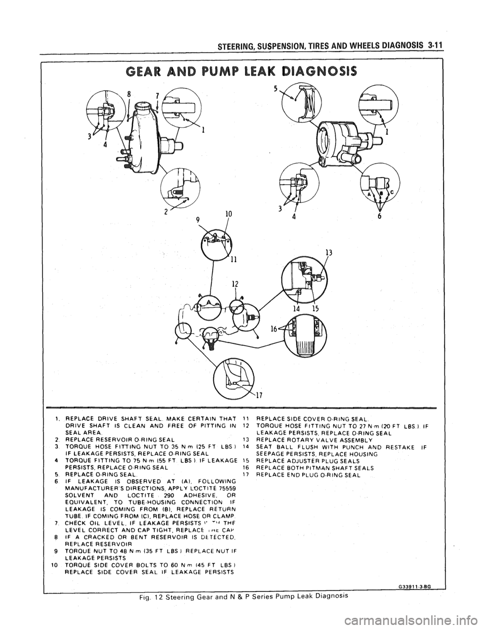
1. REPLACE DRIVE SHAFT SEAL MAKE CERTAIN THAT
DRIVE SHAFT IS CLEAN AND FREE OF PITTING IN
SEAL AREA
2 REPLACE RESERVOIR
0 RING SEAL 3 TORQUE HOSE FITTING NUT TO 35 N rn 125 FT LBS ) IF LEAKAGE PERSISTS, REPLACE O.RING SEAL 4 TORQUE FITTING TO 75 N rn 155 FT LBS 1 IF LEAKAGE
PERSISTS. REPLACE 0 RING SEAL 5 REPLACE O-RING SEAL 6 IF LEAKAGE IS OBSERVED AT (A). FOLLOWING
MANUFACTURER S DIRECTIONS. APPLY LOCTITE 75559
SOLVENT AND LOCTITE 290 ADHESIVE, OR
EQUIVALENT. TO TUBE HOUSING CONNECTION IF
LEAKAGE IS COMING FROM
101, REPLACE RETURN
TUBE IF COMING FROM IC), REPLACE HOSE OR CLAMP 7 CHECK OIL LEVEL, IF LEAKAGE PERSISTS i' ''4 THF
LEVEL CORRECT AND CAP TIGHT. REPLACE I nt CAP B IF A CRACKED OR BENT RESERVOIR IS DETECTED
REPLACE RESERVOIR
9 TORQUE NUT TO 48 N rn 135 FT LBS 1 REPLACE NUT IF
LEAKAGE PERSISTS
10 TORQUE SlDE COVER BOLTS TO 60 N m 145 FT LBS
REPLACE SlDE COVER SEAL IF LEAKAGE PERSISTS
11 REPLACE SlDE COVER O.RING SEAL
12 TORQUE HOSE FITTING NUT TO 27 N rn 120 FT LBS ) IF
LEAKAGE PERSISTS, REPLACE O.RING SEAL
13 REPLACE ROTARY VALVE ASSEMBLY
14 SEAT BALL FLUSH WITH PUNCH AND RESTAKE IF
SEEPAGE PERSISTS. REPLACE HOUSING
15 REPLACE ADJUSTER PLUG SEALS 16 REPLACE BOTH PITMAN SHAFT SEALS
17 REPLACE END PLUG O.RING SEAL
Page 149 of 1825
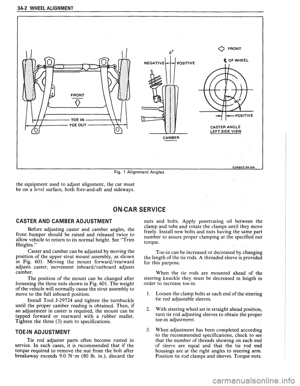
3A-2 WHEEL ALIGNMENT
0 FRONT
& OF WHEEL
CASTER ANGLE
LEFT SIDE
VIEW
CAMBER
I
Fig. 1 Alignment Angles
the equipment used to adjust alignment, the car must
be on a
level surface, both fore-and-aft and sideways.
ON-CAR SERVICE
CASTER AND CAMBER ADJUSTMENT nuts and bolts. Apply penetrating oil between the
clamp and tube and rotate the clamps until they move
Before adjusting caster and camber the freely. Install new bolts and nuts having the same part front be 'aised and twice to number to assure proper at the specified nut allow vehicle to return to its normal height. See "Trim torque. Heights."
Caster and camber can be adjusted by moving the
position of the upper strut mount assembly, as shown
in Fig. 601. Moving
the mount forward/rearward
adjusts caster; 'movement inboard/outboard adjusts
camber.
The position of the mount can be changed after
loosening the three nuts shown in Fig.
601. The weight
of the vehicle will normally cause the strut assembly to
move to the full inboard position.
Install Tool
5-29724 and tighten the turnbuckle
until the proper camber reading is obtained. Then, if
an adjustment in caster is required, the mount can be
tapped forward or rearward with a rubber mallet.
Tighten the three
(3) nuts to specifications.
TOE-IN ADJUSTMENT
Toe-in can be increased or decreased by changing
the length of the tie rods.
A threaded sleeve is provided
for this purpose.
When the tie rods are mounted ahead of the
steering knuckle they must be decreased in length in
order to increase toe-in.
1. Loosen the clamp bolts at each end of the steering
tie rod adjustable sleeves.
2. With steering wheel set in straight ahead position,
turn tie rod adjusting sleeves to obtain the proper
toe-in
adjustrne~t.
3. When adjustment has been completed according
to the recommended snecifications. check to see
Tie rod adjuster parts often become rusted in
that the number of thrkads showing on each end
service. In such cases, it is recommended that if the
of sleeve are equal and that the tie rod end
torque required to remove the nut from the bolt after housings are at the right angles to steering arm.
breakaway exceeds 9.0
Nam (80 lb. in.), discard the
Position tie rod clamps and sleeves. Torque nuts.
Page 189 of 1825
386-2 STEERING LINKAGE
LUBRICATION ADJUSTMENTS
The steering linkage should be lubricated with any
water resistant
EP type chassis lubricant at specified Toeein
intervals. Lubrication points and additional information on Adjust
the steering linkage for proper toe-in setting as
chassis lubrication can be found in Section
OB. outlined in Section 3A.
ON-CAR SERVICE 3. To remove outer ball stud, use a tool such as
RELAY ROD
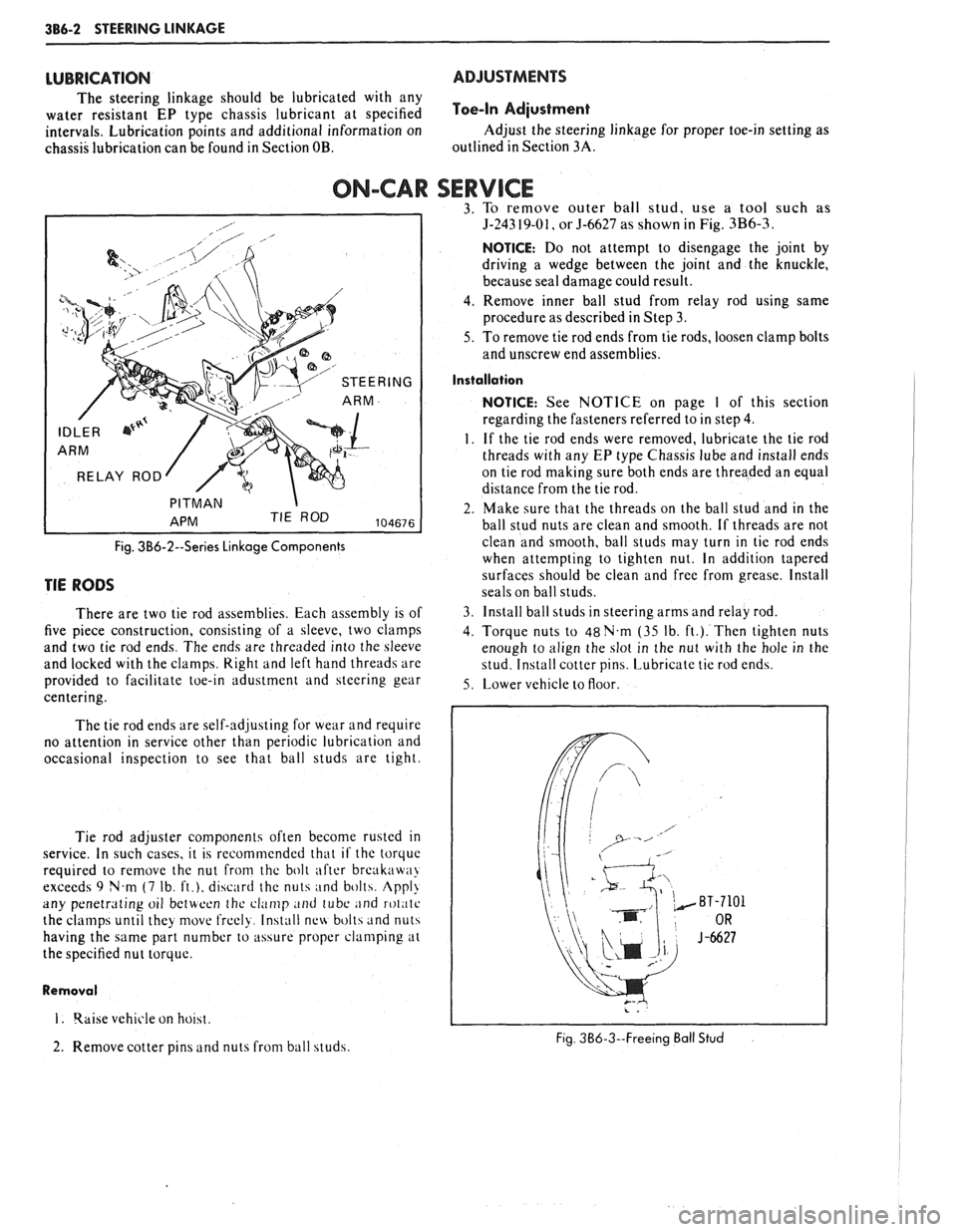
Fig. 3B6-2--Series Linkage Components
TIE RODS
There are two tie rod assemblies. Each assembly is of
five piece construction, consisting of a sleeve, two clamps
and two tie rod ends. The ends are threaded into the sleeve
and locked with the clamps.
Right and left hand threads are
provided to facilitate toe-in adustment and steering gear
centering.
The tie rod ends are self-adjusting for wear and require
no attention in service other than periodic lubrication and
occasional inspection to see that ball studs are tight.
Tie rod adjuster components often become rusted
in
service. In such cases, it is recommended that if the torquc
required to remove the nut from thc bolt after break:iw:~>
exceeds 9 N.m (7 Ib, ft.), discard the nuts and bolth. Appl!
any penetrating oil betwoon thc clamp and tube ;~nd roliitc
the clamps until they movt. frcely. Install nc\4 bolts and nuts
having the same part number to assure proper clamping at
the specified nut torque.
Removal
I. qaise vehicle on hoiht.
2. Remove cotter pins and nuts from ball studs.
5-243 19-01, or 5-6627 as shown in Fig. 3B6-3
NOTICE: Do not attempt to disengage the joint by
driving a wedge between the joint and the knuckle,
because seal damage could result.
4. Remove inner ball stud from relay rod using same
procedure as described in Step 3.
5. To remove tie rod ends from tie rods, loosen clamp bolts
and unscrew end assemblies.
Installation
NOTICE: See NOTICE on page I of this section
regarding the fasteners referred to in step
4.
1. If the tie rod ends were removed, lubricate the tie rod
threads with any
EP type Chassis lube and install ends
on tie rod making sure both ends are threaded an equal
distance from the tie rod.
2. Make sure that the threads on the ball stud and in the
ball stud nuts are clean and smooth. If threads are not
clean and smooth, ball studs may turn in tie rod ends
when attempting to tighten nut. In addition tapered
surfaces should be clean and free from grease. Install
seals on ball studs.
3. Install ball studs in steering arms and relay rod.
4. Torque nuts to 48N.m (35 Ib. ft.). Then tighten nuts
enough to align the slot in the nut with the hole in the
stud. Install cotter pins. Lubricate tie rod
end\.
5. Lower vehicle to floor.
Fig. 3B6-3--Freeing Ball Stud
Page 203 of 1825
3B7-10 POWER STEERING
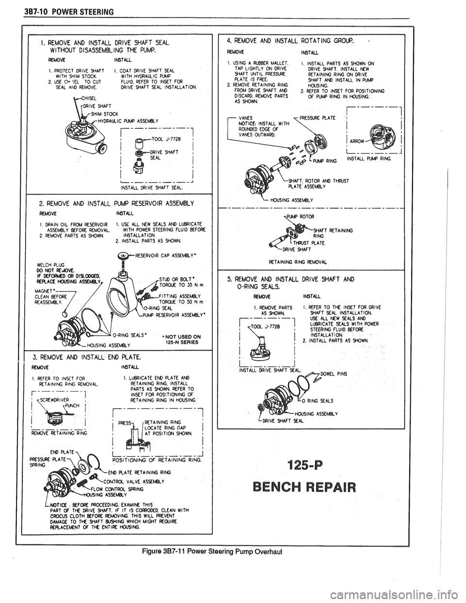
I. REMOVE AND INSTALL DRlVE SHAFT SEAL W l THOUT DISASSEMBL ING THE PUMP.
REMOVE It6TALL
I PROTECT DRlVE SHAFT I COAT DRIVE SHAFT SEAL WITH SHIM STOCK WITH HYDRAULIC PVMP 2 USE Ch 5EL TO CUT FLUID. REFER TO INSET FOR
SEAL AND REMOVE DRIVE SHAFT SEAL INSTALLATION
DRAUCIC WMP ASSEMBLY
TOOL J-7728
1
i
j
I
2. REMOVE AND INSTALL PUMP RESERVOIR ASSEMBLY I REMOVE INSTALL I I. DRAIN OIL FROM RESERVOIR I. USE ALL NEW SEALS AND LUBRICATE
ASSEMBLY BEFORE REMOVAL. WlTH
POWER STEERING FLUID BEFORE 2. REMOVE PARTS AS SHOWN. INSTALLAT
ION. 2. INSTALL PARTS AS SHOWN.
TORQUE TO SJ N m
FITTING ASSEMBLY
TORQUE TO 50 N m
UMP REYRVOIR ASSEMBLY *
O-RING SEALS * . NOT USED ON
HOUSING ASSEMBLY 125-N SERIES
1 1 I
REFER TO INSET FOR I. LLleRlCATE EN) PLATE AND I RETAINING RING. INSTALL
PARTS AS WOWN. REFER TO
INSET FOR POSITIONING
OF I
I RETAINING RING 1
- - - - - - - LOCATE RlNG GAP I REMOVE RETAINING RING AT POSITION WOWN I
POSITIONING OF RETAINING
ATE RETAINING RlNG
VALVE
ASSEWY
OW CONTROL SPRING
LWTI(X : BEFORE PROCEEDING. EXAMIN THIS
PART Of TM DRIVE WAFT. IF IT IS C CROCUS CLOTH BEFORE REMOVING. THIS WILL PREVENT DAMAGE TO TM WAFT WING WHICH MIGHT REWIRE RERACEMNT OF 1% ENTIRE HOUSING.
-- J RING.
4. REMOVE AND INSTALL ROTATING GROUP.
REMOVE INSTALL
1. USING A RUBBER MALLET. I. INSTALL PARTS AS SHOWN ON
TAP LIGHTLY ON DRIVE
DRIVE WAFT. INSTALL NEW
WAFT UNTIL
PRESSVRE RETAINING RING ON DRIVE
PLATE IS FREE. SHAFT AND INSTALL IN PW 2. REMOVE RETAINING RING HOUSING.
FROM DRlVE WAFT AM 2, REFER TO INSET FOR POSITIONING
DISCARD. REMOVE PARTS OF PUMP RING IN HOUSING.
AS SHOWN.
7 VANES r------I T PRESSURE PLATE '1 NOTICE: INSTALL WITH
ROUNDED EDGE OF VANES OVTWARD.
WAFT. ROTOR AN) TWST PLATE ASSEMBLY
PUIAP RING.
C
\- HOUSING ASSEMLY
TpW ROTOR
WAFT RETAINING
I RETAINING RlNG REMOVAL I
5. REMOVE AND INSTALL DRIVE SHAFT AND
O-RING SEALS.
I RLAOM INSTML
I. REMOVE PARTS 1. REFER TO TM INSET FOR DRlVE
AS WOWN WAFT SEAL INSTALLATION
USE ALL NW SEALS AND 1 LVBRlCATE SEALS WlTH POWER J-7728 STEERING FLUID BEFORE
INSTALLATION
! 2. INSTALL PARTS AS WOWN .
I
INSTALL DRIVE SHAFT
HOUSING ASSEMBLY
I LDRIVE WAFT SEAL
BENCH REPAIR
Figure 3B7-11 Power Steering Pump Overhaul
Page 204 of 1825
POWER STEERING 387.1 "1
GENEML DESCRIPTION
These Integral Power Steering Gears
have a control valve which directs oil
to either side of the rack piston. The
rack piston converts hydraulic power
into mechanical force. This force is
transmitted to the mating
pitman
shaft teeth, through the pitman shaft
to the steering linkage.
The model
800 incorporates a
recirculating ball system in which
steel balls act as a rolling thread
between a steering worm-shaft and
the rack-piston.
I., U.. Per1 *.a. I -HOUSING. STEERING GEAR 1 -RACE, THRUST BEAPING (WORM)
3 -BEARING ASSY. ROLLER THRUST IWORMI 4 -RACE. IHRUST BEARING (WOWMI 5 -WORM. SlEERlNG 6 -SEAL. "0" WING (STUB SHAFT) 7 - SHAFT. STUB 8 - SPOOL. VALVE
9 - SEAL. "0 RING ISPOOL) I0 -BODY. VALVE I I - RING. VALVE BODY 13) I2 -SEAL. "0" RlNG [VALVE BODY) 131 13 - RETAINER. BEARING (ADJUSIERI I4 - SPACER, THRUST BEARING
I5 -RACE UPPER THRUST BEARING ISMALLI 16.- BEARING. UPPER THRUST I7 - RACE UPPER THRUST BEARING ILARGEI IB - SEAL. "0" RlNG IADJUSTER)
Whenever a part wh~ch
forms a sealing surface for an "0"
ring is removed, the "0" rlng seal
should also be removed and
replaced with a new seal. When-
ever one of the
P~tman shaft or
stub shaft seals are removed all
adjacent seals should be removed
and replaced
w~th new seals.
Lubr~cate all new seals w~th
power steer~ng flu~d to ease assembly
I,, Ue Pet1 Were I9 PLUG ADJUSTER 10 BEARING NEEDLE ?I SEAL SIUb SHAFT ?I SEAL SlUB SHAFT DUST
23 RlNG RETAINING
24 NUT ADJUSTER PLUG LOCK
IS BEARING ASSY NEEDLE PITMAN SHAFT
16 SEAL PITMAN SHAFT ISINGLE LIP 17 WASHER SEAL BACK-UP [PlTMnN SHAFT! 18 -SEAL PITMAN SHAFT [DOUBLE LIP1 29 -WASHER SEAL BACK-UP \PITMAN SHAFT
30 -RING RETAINING iPlTMAN SHAFT SEAL
31 -WASHER PITMAN SHAFT LOCK
32 - NUT PITMAN SHAFT
33 NUT RACK PISTON
34 -BALL
35
GUIDE BALL RETURN 2 36 CLAMP BALL RETURN GUIDE
tar1 Yemr SCREW ASSY LOCKWA5HER L It PLUG RACK PISTON
SEAL 0 RlNG IRACK PISTONI RlNG RACK PISTON
SEAL 0 RING HOUSING END PLUG
PLUG HOUSING END
RlNG RETAINING HOUSING END PLUG
GEAR ASSY
PITMAN SHAFT SEAL ASSY GASKET
COVER ASSY HOUSING SIDE BOLT HEX HEAD SIDE COVER, 4 NUT LASH ADJUSTER
SPRING CHECK VALVE
POPPET CHECK VALVE
CONNECTOR INVERTED FLARE
CONNECTOR INVERTED FLARE
--- - I
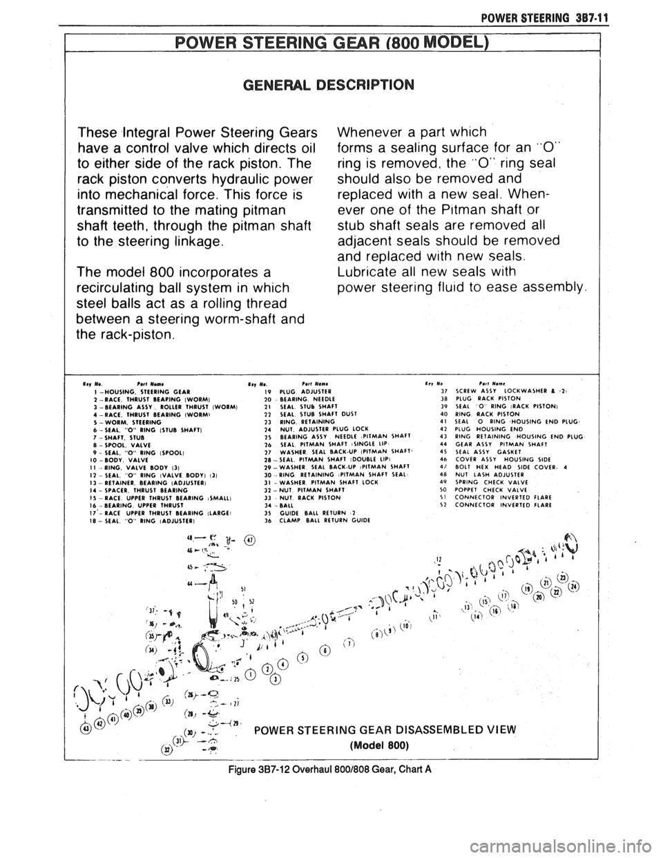
Figure 387-12 Overhaul 8001808 Gear, Chart A
Page 212 of 1825
FRONT SUSPENSION 3C-1
SEC"T0RI 3C
FRONT SUSPENS
NOTICE: All front suspension fasteners are an important attaching part in that it could affect the
performance of vital parts and systems, and/or could result in major repair expense. They must be replaced with
one of the same part number or with an equivalent part if replacement becomes necessary. Do not use a
replacement part of lesser quality or substitute design. Torque values must be used as specified during reassembly
to assure proper retention of this part.
NOTICE: Never attempt to heat, quench or straighten any front suspension part. Replace it with a new part
or
damage to the part may result.
CONTENTS
General lnformation ....................................................................................................... 3C-I
On-Car Service ................................................................................................................... 3C- I
Specifications ..................................................................................................................... 3C- 10
GENERAL INFORMATION
The front suspension is designed to allow each
wheel to compensate for changes in the road surface ON-CAR SERVICE
level without appreciably affecting the opposite wheel. WHEEL BEARINGS
Each wheel is independently connected to the frame by
The proper functioning of the front suspension
a steering
kunckle, strut assembly, ball joint, and lower cannot be maintained unless the front wheel tapered arm. The steering in a roller bearings are correctly adjusted. The bearings
prescribed three dimensional arc. The front wheels are
must be a slip fit on the spindle and the inside diameter held in proper relationship to each other by two tie rods of the bearings should be lubricated to insure proper which are connected to steering arms on the knuckles ~h~ spindle nut must be a free-running fit and to the relay rod assembly.
on the threads.
Coil chassis springs are mounted between the
spring housings on the front crossmember and the
lower control arms. Ride control is provided by double,
direct acting strut assemblies. The upper portion of
each strut assembly extends through the fender well
and attaches to the upper mount assembly with a nut.
Side roll of the front suspension is controlled by
a spring steel stabilizer shaft. It is mounted in rubber
bushings which are held to the frame side rails by
brackets. The ends of the stabilizer are connected to the
lower control arms by link bolts and are isolated by
rubber grommets.
The inner ends of the lower control arms have
pressed in bushings. Bolts (passing through the
bushings) attach the arm to the suspension
crossmember. The lower ball joint assembly is a press
fit in the arm and attaches to the steering knuckle with
a torque prevailing nut.
Rubber grease seals are provided at ball socket
assemblies to keep dirt and moisture from entering the
joint and damaging bearing surfaces.
Adjustment
Figure 602
NOTICE: See NOTICE on Page 3C-1
of this
section.
1. Remove dust cap from hub.
2. Remove cotter pin from spindle and spindle nut.
3. Tighten the spindle nut to 16 Nsm (12 lb. ft.)
while turning the wheel assembly forward by
hand to fully seat the bearings. This will remove
any grease or burrs which could cause excessive
wheel bearing play later.
4. Back off the nut to the "just loose" position.
5. Hand tighten the spindle nut. Loosen spindle nut
until either hole in the spindle lines up with a slot
in the nut. Not
nlore than 1/2 flat.
6. Install
new cotter pin. Bend the ends of the cotter
pin against nut, cut off extra length to ensure ends
will not interfere with the dust cap.
7. Measure the looseness in the hub assembly. There
will be
from .03 to . l3mm (.001 to .005 inches)
end play when properly adjusted.
8. Install dust cap on hub.
FRONT SUSPENSION
Refer to Fig. 610 for illustration of attachment
provisions for the bolted-on front suspension
suspension
crossmember.