1988 PONTIAC FIERO oil
[x] Cancel search: oilPage 93 of 1825
1 Dl-14 R-4 AIR CONDITIONING COMPRESSOR OVERHAUL
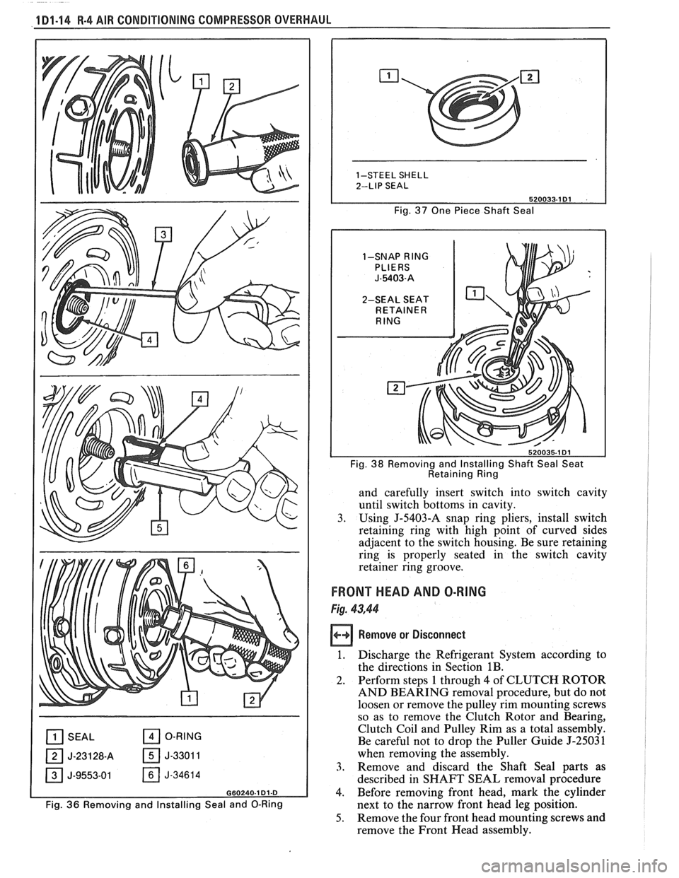
[il SEAL O-RING
OJ-23128-A 05-33011
J-9553-01 J-34614
G60240.1 Dl-D
Fig. 36 Removing and Installing Seal and 0-Ring Fig.
37 One
Piece Shaft Seal
1-SNAP
RING
2-SEAL SEAT
I Fig. 38 Removing and Installing Shaft Seal Seat
Retaining Ring
and carefully insert switch into switch cavity
until switch bottoms in cavity.
3. Using J-5403-A snap ring pliers, install switch
retaining ring with high point of curved sides
adjacent to the switch housing. Be sure retaining
ring is properly seated in the switch cavity
retainer ring groove.
FRONT HEAD AND O-RING
Fig. 43,44
Remove or Disconnect
1. Discharge the Refrigerant System according to
the directions in Section
1B.
2. Perform steps 1 through 4 of CLUTCH ROTOR
AND BEARING removal procedure, but do not
loosen or remove the pulley rim mounting screws
so as to remove the Clutch Rotor and Bearing,
Clutch Coil and Pulley Rim as a total assembly.
Be careful not to drop the Puller Guide
5-2503 1
when removing the assembly.
3. Remove and discard the Shaft Seal parts as
described in SHAFT SEAL removal procedure
4. Before removing
front head, mark the cylinder
next to the narrow front head leg position.
5. Remove
the four front head mounting screws and
remove the Front Head assembly.
Page 94 of 1825
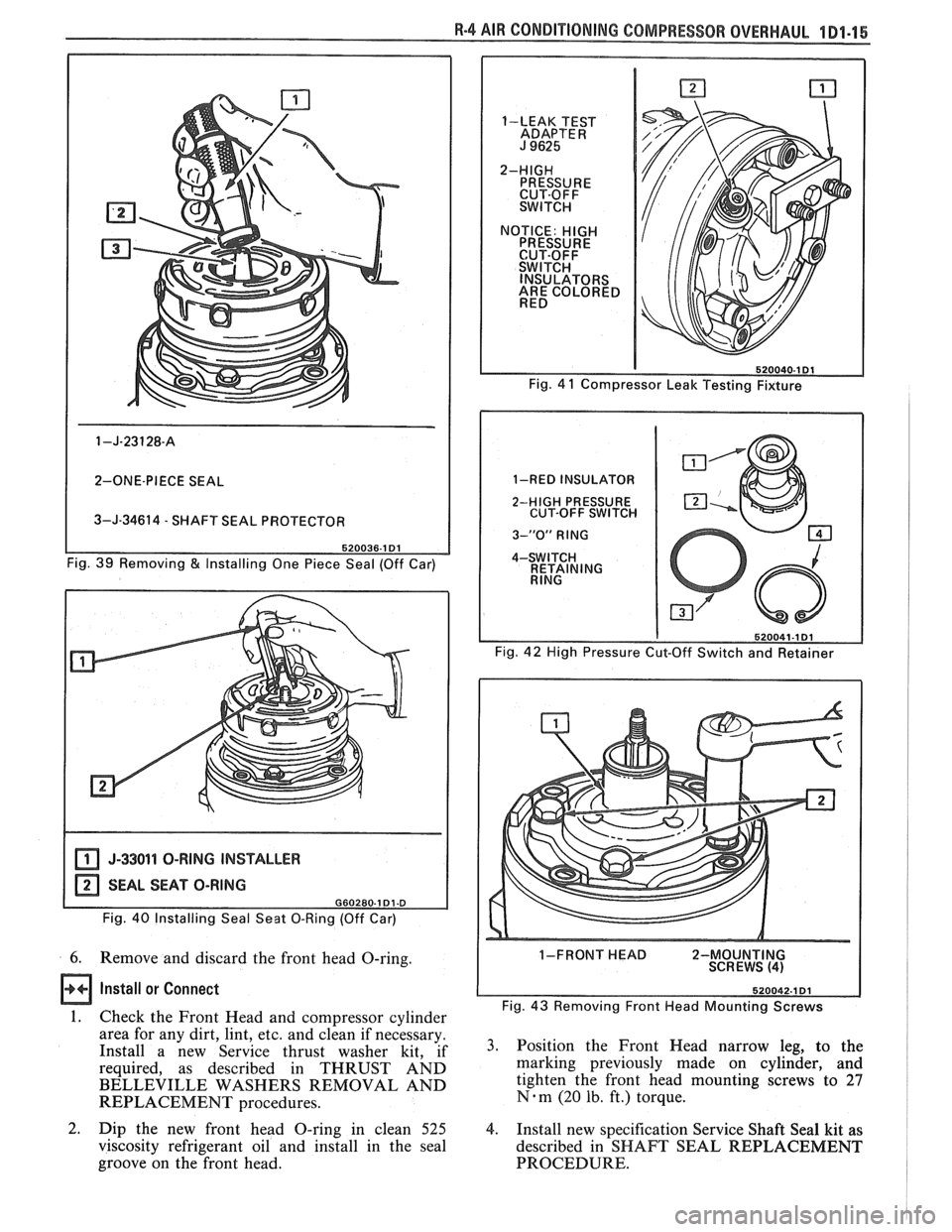
I 2-ONE-PIECE SEAL I
3-J-34614 - SHAFT SEAL PROTECTOR
Fig. 39 Removing
& Installing One Piece Seal (Off Car)
I J-33011 O-RING INSTALLER I
Fig. 40 Installing Seal Seat 0-Ring (Off Car)
6. Remove and discard the front head O-ring.
Install or Connect
1. Check the Front Head and compressor cylinder
area for any dirt, lint,
etc. and clean if necessary.
Install a new Service thrust washer kit, if
required, as described in THRUST AND
BELLEVILLE WASHERS REMOVAL AND
REPLACEMENT procedures.
2. Dip the new front head O-ring in clean 525
viscosity refrigerant oil and install in the seal
groove on the front head.
-4 AIR CONDITIONING COMPRESSOR OVERHAUL 1 Dl-15
I
1-LEAK TEST
ADAPTER
J 9625
2-HIGH PRESSURE
CUT-OFF
SWITCH
NOTICE:
HIGH PRESSURE
CUT-OFF
SWITCH INSULATORS
ARE COLORED
RED
Fig. 4
1 Compressor Leak Testing Fixture
1-RED INSULATOR
2-HIGH PRESSURE
CUT-OFF SWITCH
3-"0" RlNG
4-SWITCH
RETAINING
RING
Fig. 42 High Pressure Cut-Off Switch and Retainer
I-FRONT HEAD 2-MOUNTING
SCREWS
(4)
Fig. 43 Removing Front Head Mounting Screws
3. Position the Front Head narrow leg, to the
marking previously made on cylinder, and
tighten the front head mounting screws to
27
N-m (20 lb. ft.) torque.
4. Install new specification Service Shaft Seal kit as
described in SHAFT SEAL REPLACEMENT
PROCEDURE.
Page 95 of 1825
1D1-16 R-4 AIR CONDITIONING COMPRESSOR OVERHAUL
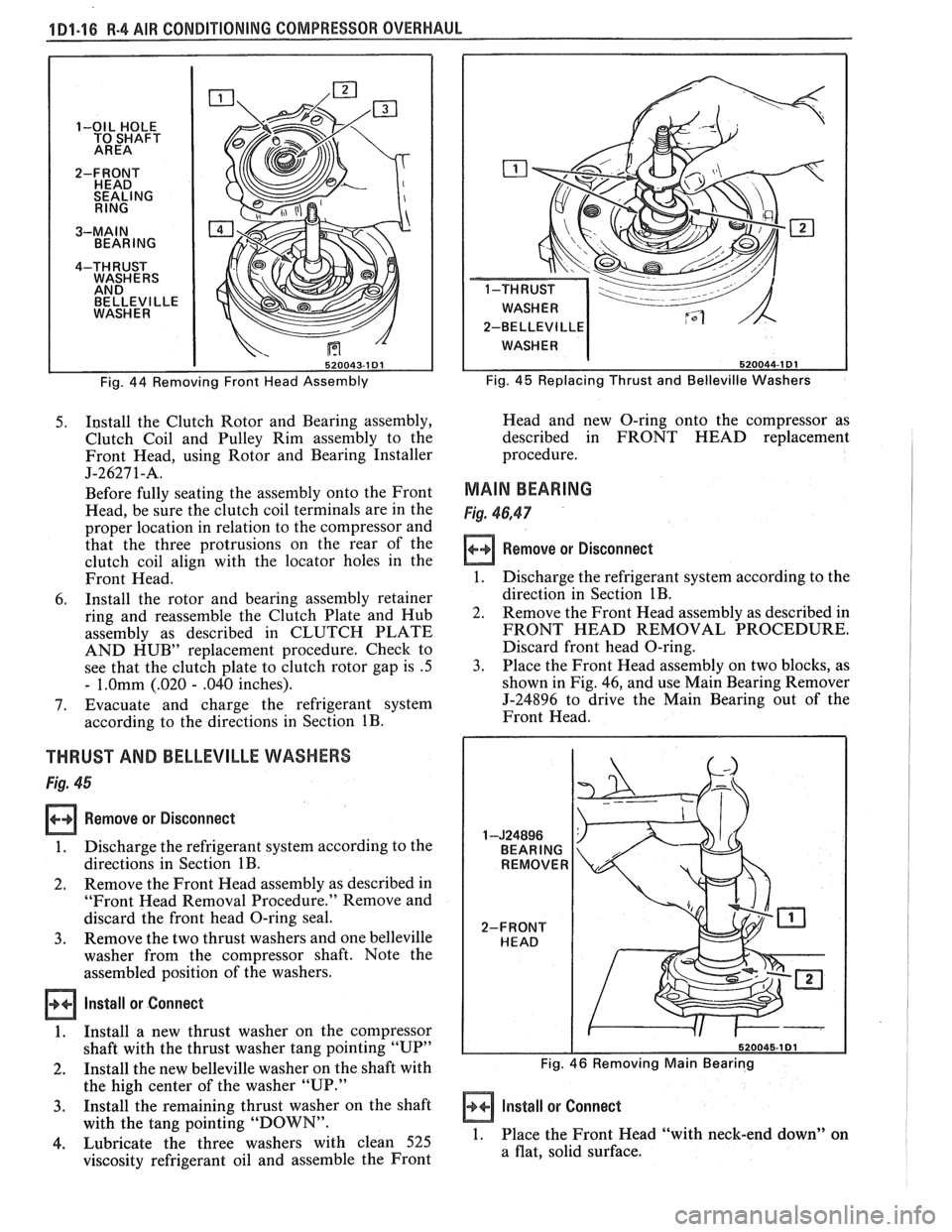
BELLEVl LLE
2-BELLEVI
LLE
Fig. 44 Removing Front Head Assembly Fig. 45 Replacing Thrust
and Belleville Washers
5. I~stall the Clutch Rotor and Bearing assembly,
Clutch Coil and Pulley Rim assembly to the
Front Head, using Rotor and Bearing Installer
J-2627 1-A.
Before fully seating the assembly onto the Front
Head, be sure the clutch coil terminals are in the
proper location in relation to the compressor and
that the three protrusions on the rear of the
clutch coil align with the locator holes in the
Front Head.
6. Install the rotor and bearing assembly retainer
ring and reassemble the Clutch Plate and Hub
assembly as described in CLUTCH PLATE
AND HUB" replacement procedure. Check to
see that the clutch plate to clutch rotor gap is
.5
- 1.Omm (.020 - .040 inches).
7. Evacuate and charge the refrigerant system
according to the directions in Section
1B.
THRUST AND BELLEVILLE WASHERS
Fig. 45
Remove or Disconnect
1. Discharge the refrigerant system according to the
directions in Section
1B.
2. Remove
the Front Head assembly as described in
"Front Head Removal Procedure." Remove and
discard the front head O-ring seal.
3. Remove the two thrust washers and one belleville
washer from the compressor shaft. Note the
assembled position of the washers.
Install or Connect
1. Install a new thrust washer on the compressor
shaft with the thrust washer tang pointing "UP"
2. Install the new belleville washer on the shaft with
the high center of the washer "UP." Head
and new O-ring onto the compressor as
described in FRONT HEAD replacement
procedure.
MAIN BEARING
Fig. 46,47
Remove or Disconnect
1. Discharge the refrigerant system according to the
direction in Section
1B.
2. Remove the Front Head assembly as described in
FRONT HEAD REMOVAL PROCEDURE.
Discard front head O-ring.
3. Place the Front Head assembly on two blocks, as
shown in Fig. 46, and use Main Bearing Remover
J-24896 to drive the Main Bearing out of the
Front Head.
Fig. 46 Removing Main Bearing
-
3. Install the remaining thrust washer on the shaft Install or Connect
with the tang pointing "DOWN".
4. Lubricate the three washers with clean 525 1. Place the Front Head "with neck-end down" on
viscosity refrigerant oil and assemble the Front a
flat, solid surface.
Page 96 of 1825
R-4 AIR CONDITIONING COMPRESSOR OVERHAUL 1 Dl-17
2. Align
the new Main Bearing and the Bearing
Installer
5-24895 squarely with the bearing bore
of the Front Head and drive the bearing into the
Front Head. The Installer J-24895 must seat
against the Front Head to insert the bearing to
the proper clearance depth.
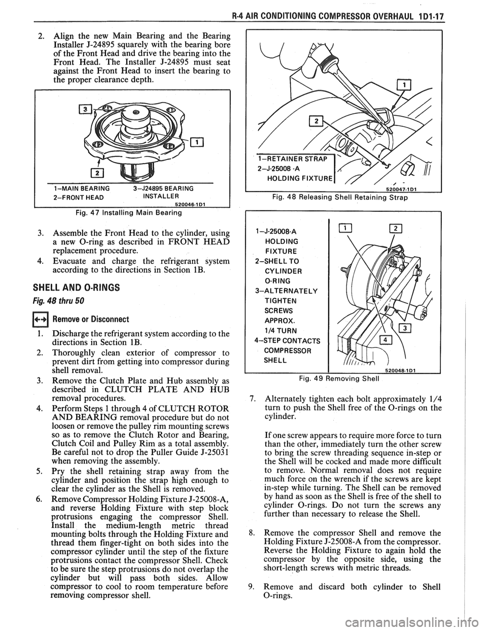
Fig. 47 Installing Main Bearing
3. Assemble the Front Head to the cylinder, using
a new O-ring as described in FRONT HEAD
replacement procedure.
4. Evacuate and charge the refrigerant system
according to the directions in Section
1B.
SHELL AND O-RINGS
Fig. 48 thru 50
Remove or Disconnect
1. Discharge the refrigerant system according to the
directions in Section
1B.
2. Thoroughly clean exterior of compressor to
prevent dirt from getting into compressor during
shell removal.
3. Remove the Clutch Plate and Hub assembly as
described in CLUTCH PLATE AND HUB
removal procedures.
4. Perform Steps 1 through 4 of CLUTCH ROTOR
AND BEARING removal procedure but do not
loosen or remove the pulley rim mounting screws
so as to remove the Clutch Rotor and Bearing,
Clutch Coil and Pulley Rim as a total assembly.
Be careful not to drop the Puller Guide J-25031
when removing the assembly.
5. Pry the shell-retaining strap away from the
cylinder and position the strap high enough to
clear the cylinder as the Shell is removed.
6. Remove Compressor Holding Fixture J-25008-A,
and reverse Holding Fixture with step block
protrusions engaging the compressor Shell.
Install the medium-length metric thread
mounting bolts through the Holding Fixture and
thread them finger-tight on both sides into the
compressor cylinder until the step of the fixture
protrusions contact the compressor Shell. Check
to be sure the step protrusions do not overlap the
cylinder but will pass both sides. Allow
compressor to cool to room temperature before
removing compressor shell.
2-J-25008 -A
HOLDING FIXTURE
Fig. 48 Releasing Shell Retaining Strap
HOLDING FIXTURE
2-SHELL TO
CYLINDER
O-RING
3-ALTERNATELY
TIGHTEN
SCREWS
APPROX.
114 TURN
4-STEP CONTACTS
COMPRESSOR
SHELL
Fig. 49 Removing Shell
7. Alternately tighten each bolt approximately 1/4
turn to push the Shell free of the O-rings on the
cylinder.
If one screw appears to require more force to turn
than the other, immediately turn the other screw
to bring the screw threading sequence in-step or
the Shell will be cocked and made more difficult
to remove. Normal removal does not require
much force on the wrench if the screws are kept
in-step while turning. The Shell can be removed
by hand as soon as the Shell is free of the shell to
cylinder O-rings. Do not turn the screws any
further than necessary to release the Shell.
8. Remove the compressor Shell and remove the
Holding Fixture J-25008-A from the compressor.
Reverse the Holding Fixture to again hold the
compressor by the opposite side, using the
short-length screws with metric threads.
9. Remove and discard both cylinder to Shell
O-rings.
Page 97 of 1825
1 Dl-18 R-4 AIR CONDITIONING COMPRESSOR OVERHAUL
Install or Connect
1. Check the compressor cylinder assembly and
interior of the compressor Shell to be sure they
are free of lint, dirt, etc.
2. Dip a new cylinder-to-shell O-ring in clean 525
viscosity refrigerant oil and install in the rear
O-ring groove of the cylinder. Be careful in
moving the O-ring across the cylinder surface to
prevent damaging the O-ring.
3. Dip the remaining cylinder-to-shell O-ring in the
525 oil and install it in the front O-ring groove of
the cylinder.
4. Also coat inner O-ring surface
of compressor
Shell with oil. Place the compressor Shell on the
cylinder and rotate the retaining strap to its
original location.
5. Attach the
Shell Installing Fixture
J-25008-A to
the Holding Fixture J-25008-A, using the
long-bolts and plate washers of the set. Align the
step projections of the Installing Fixture
J-25008-A, to contact the compressor Shell
evenly on both sides.
6. Push the compressor shell as close to the O-ring
as possible by hand and check for equal alignment
of the shell around the cylinder. Tighten the
Fixture screws finger tight.
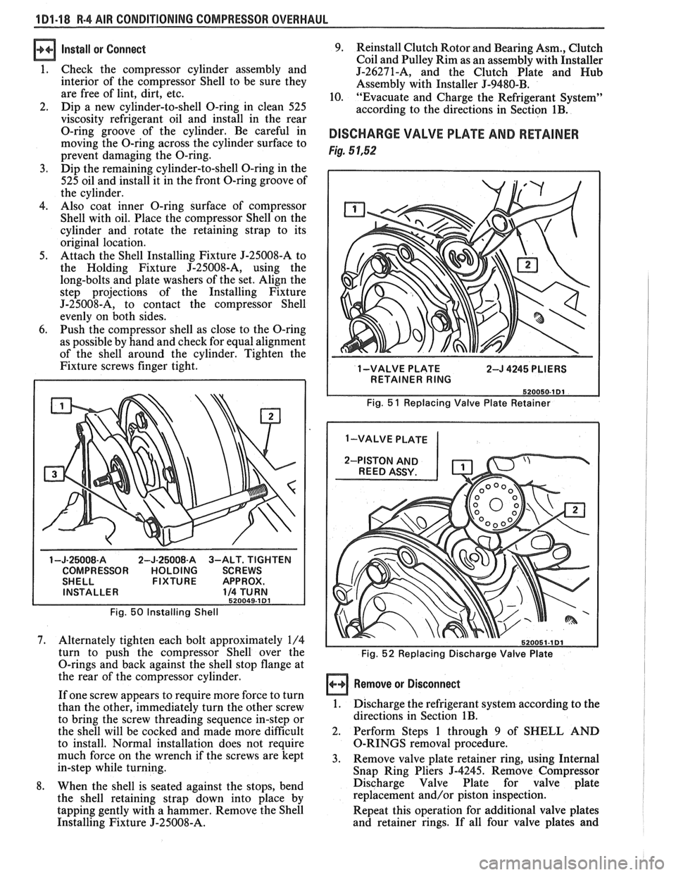
1 -J-25008-A 2-J-25008-A 3-ALT. TIGHTEN
COMPRESSOR HOLDING SCREWS
SHELL FIXTURE APPROX.
INSTALLER
114 TURN 520049-1 Dl
Fig. 50 Installing Shell
7. Alternately tighten each bolt approximately 1/4
turn to push the compressor Shell over the
O-rings and back against the shell stop flange at
the rear of the compressor cylinder.
If one screw appears to require more force to turn
than the other, immediately turn the other screw
to bring the screw threading sequence in-step or
the shell will be cocked and made more difficult
to install. Normal installation does not require
much force on the wrench if the screws are kept
in-step while turning.
8. When the shell is seated against the stops, bend
the shell retaining strap down into place by
tapping gently with a hammer. Remove the Shell
Installing Fixture J-25008-A. 9.
Reinstall Clutch Rotor and Bearing Asm., Clutch
Coil and Pulley Rim as an assembly with Installer
5-262714, and the Clutch Plate and Nub
Assembly with Installer J-9480-B.
10.
"Evacuate and Charge the Refrigerant System"
according to the directions in Section
1B.
DISCHARGE VALVE PLATE AND RETAINER
Fig. 5 1,52
1 -VALVE PLATE
2-J 4245 PLIERS
I RETAINER RING I
Fig. 5 1 Replacing Valve Plate Retainer
1 -VALVE PLATE
Fig.
52 Replacing Discharge Valve Plate
Remove or Disconnect
1.
Discharge the refrigerant system according to the
directions in Section
1B.
2. Perform Steps 1 through 9 of SHELL AND
O-RINGS removal procedure.
3. Remove valve plate retainer ring, using Internal
Snap Ring Pliers
J-4245. Remove Compressor
Discharge Valve Plate for valve plate
replacement and/or piston inspection.
Repeat this operation for additional valve plates
and retainer rings. If all four valve plates and
Page 98 of 1825
R-4 818 CONDITIONING COMPRESSOR OVERHAUL 1D1-19
retainers are to be removed, remove two sets and
then rotate compressor and Holding Fixture
J-25008-A in vise for access to the remaining two
valve plates and retainers.
Install or Connect
1. Install Discharge Valve Plates and/or Retainers.
Reposition compressor and Holding Fixture in
vise as necessary for access.
Valve plates must
be tight
following retainer assembly.
2. Reinstall compressor Shell as described in
SHELL AND O-RINGS replacement
procedures.
3. Evacuate and charge the refrigerant system
according to the directions in Section
1B.
CYLINDER AND SHAFT ASSSEMBLY
Remove or Disconnect
Discharge the refrigerant system according to the
directions in Section
1B.
Remove the Clutch Plate and Hub assembly as
described in CLUTCH PLATE AND HUB
removal procedure.
Perform Steps
1 through 4 of CLUTCH ROTOR
AND BEARING removal procedure but do not
loosen or remove the pulley rim mounting screws.
Remove the Clutch Rotor and Bearing, Clutch
Coil and Pulley Rim as an assembly. Be careful
not to drop the Puller Guide J-25031, when
removing the assembly.
Remove the shaft seal as described in SHAFT
SEAL removal procedure.
Remove the front head as described in FRONT
HEAD REMOVAL procedure.
Remove the thrust and belleville washers as
described in THRUST AND BELLEVILLE
WASHERS removal procedures.
Remove the compressor shell as described in
SHELL removal procedure.
Remove the discharge valve plate and retainer as
described in DISCHARGE VALVE PLATE
AND RETAINER removal procedure.
Remove the high pressure relief valve as
described in
HIGH PRESSURE RELIEF
VALVE REMOVAL PROCEDURE.
L
Install or Connect
1. Replace above parts in opposite order.
2. Evacuate and charge the refrigerant system
according to the directions in Section
1B.
LEAK TESVING (EXTERNAL AND INTERNAL)
Bench-Check Procedure
1. Install Test Plate J-9625-A on Rear Head of
compressor.
2. Attach center hose of Manifold Gage Set on
Charging Station to a refrigerant drum standing
in an upright position and open valve on drum.
3. Connect Charging Station high and low pressure
lines to corresponding fittings on Test Plate J-9625-A, using
5-5420 Gage
Adapters if hoses
are not equipped with valve depressors.
Suction port (low-side) of compressor has
large internal opening. Discharge port
(hi-side) has smaller internal opening into
compressor.
Open low-pressure control, high-pressure control
and refrigerant control on Charging Station to
allow refrigerant vapor to flow into compressor.
Using a Leak Detector, check for leaks at
Pressure Relief Valve, compressor shell to
cylinder, compressor front head seal, and
compressor Shaft Seal. After checking, shut off
low pressure control and high pressure control on
Charging Station.
If an external leak is present, perform the
necessary corrective measures and recheck for
leaks to make certain the leak has been corrected.
Loosen the Manifold Gage hose connections to
the Gage Adapters J-5420 connected to the low
and high sides and allow the vapor pressure to
release from the compressor.
Disconnect both Gage Adapters
5-5420 from the
Test Plate J-9625-A.
Rotate the complete compressor assembly (not
the crankshaft or drive plate hub) slowly several
turns to distribute oil to all cylinder and piston
areas.
Install a shaft nut on the compressor crankshaft
if the drive plate and clutch assembly are not
installed.
Using a box-end wrench or socket and handle,
rotate the compressor crankshaft or clutch drive
plate on the crankshaft several turns to ensure
piston assembly to cylinder wall lubrication.
Connect the Charging Station high pressure line
or a high pressure gage and Gage Adapter J-5420
to the Test Plate J-9625-A high side connector.
Attach an Adapter
9-5420 to the suction or low
pressure port of the Test Plate
J-9625-19 to open
the Schrader-type valve.
Oil will drain out of the compressor suction port
adapter if the compressor is positioned with the
suction port downward.
Attach the compressor to the Holding Fixture
J-25008-A using metric mounting screws. Clamp
the compressor Holding Fixture in a vise so that
the compressor can be manually turned with a
wrench.
Using a wrench, rotate the compressor crankshaft
or drive plate hub ten complete revolutions at a
speed of approximately one-revolution per
second.
Turning the compressor at less than
one-revolution per second can result in a lower
pump-up pressure and disqualify a good pumping
compressor.
Observe the reading on HIGH pressure gage at
the completion of the tenth revolution of the
compressor. The pressure reading for a good
pumping compressor should be 344.75
kPa (50 p.
s.i.) or above. A pressure reading of less than 3 10.
275 kPa (45 p.s.i.) would indicate one or more
Page 99 of 1825
101.20 R-4 AIR CONDITIONING COMPRESSOR OVERHAUL
suction and/or discharge valves leaking, an
internal leak or an inoperative valve, and the
compressor should be disassembled and checked
for cause of leak. Repair as needed, reassemble
and repeat the pump-up test. Externally leak test.
When the pressure pump-up test is completed,
release the air pressure from the HIGH side and
remove the Gage Adapters J-5420 and Test Plate
J-9625-A. 18. On the R-4 compressor, tilt the compressor so
that the compressor suction and discharge ports
are down. Drain the oil from the compressor.
19. Allow the compressor to drain for
10 minutes,
then charge with the proper amount of oil. The
oil may be poured into the suction port.
If further assembly or processing is required, a
shipping plate or Test Plate J-9625-A should be
installed to keep out air, dirt and moisture until
the compressor is installed.
Page 100 of 1825
R-4 AIR CONDITIONING COMPRESSOR OVERHAUL 1 Dl-21
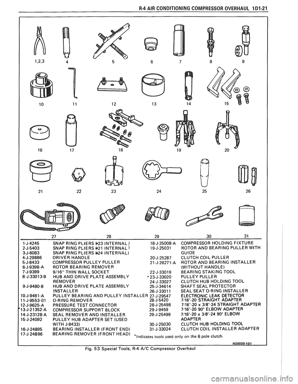
SNAP RING PLIERS b23 INTERNAL ) 18-J-25008-A COMPRESSOR HOLDING FIXTURE
SNAP
RING PLIERS @21 INTERNAL) 19-J-25031 ROTOR
AND BEARING PULLER WITH SNAP RING PLIERS 44424 INTERNAL)
GUIDE
DRIVER HANDLE 20-J-25287 CLUTCH COIL PULLER
COMPRESSOR PULLEY PULLER 21-J-26271.A ROTOR AND BEARING INSTALLER
ROTOR BEARING REMOVER (WITHOUT HANDLE)
9/16"
THIN WALL SOCKET
22-J-33019 BEARING STAKING TOOL
HUB AND DRIVE PLATE ASSEMBLY "23-J-33020 PULLEY PULLER
REMOVER 24-J-33027 CLUTCH HUB HOLDING TOQL
HUB AND DRIVE PLATE ASSEMBLY 25-J-34614 SHAFT SEAL PROTECTOR
INSTALLER 26-J-33011 SEAL SEAT O-RING INSTALLER
PULLEY BEARING AND PULLEY INSTALLER
27-J-29547 ELECTRONIC LEAK DETECTOR
O-RING REMOVER 28-J-5420 7116"-20 STRAIGHT ADAPTER
PRESSURE TEST CONNECTOR 28-J-25498 7116"-20 x 3/8-24 STRAIGHT ADAPTER
COMPRESSOR SUPPORT BLOCK 29-J-9459 7116"-20 90" ELBOW ADAPTER
SEAL REMOVER AND INSTALLER 29-J-25499 7/16-20 x 318"-24 90" ELBOW
PULLEY HUB ADAPTER SET (USED ADAPTER
WITH
J-8433) 30-J-25030 CLUTCH HUB HOLDING TOOL
BEARING INSTALLER (FRONT END) 31-J-33024 CLUTCH COIL INSTALLER ADAPTER
HEAD) "Indicates tools used only on the 6 pole clutch
Fig.
53 Special Tools, R-4 A/C Compressor Overhaul