1988 PONTIAC FIERO oil
[x] Cancel search: oilPage 213 of 1825
3C-2 FRONT SUSPENSION
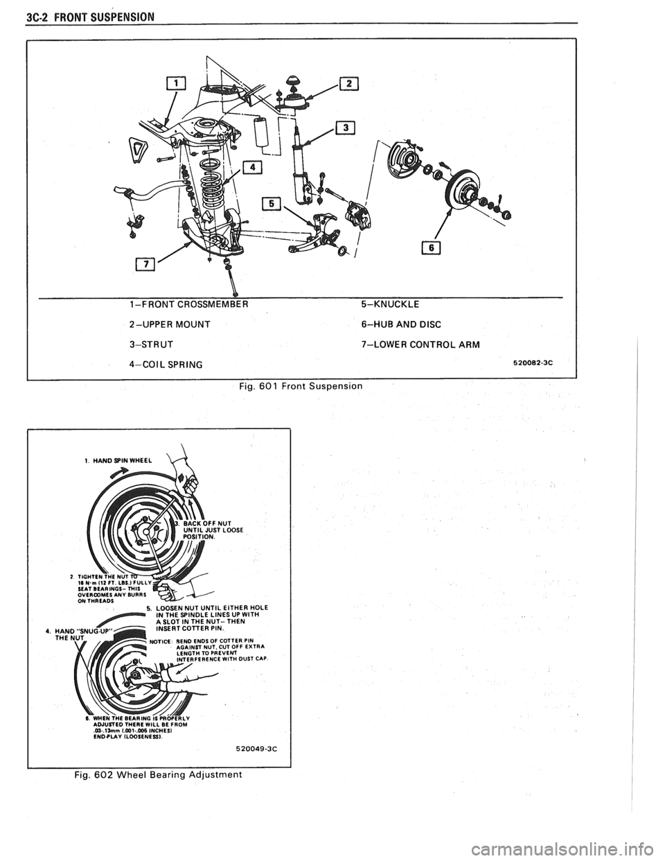
Y 1-FRONT CROSSMEMBER 5-KNUCKLE
2-UPPER MOUNT 6-HUB
AND
DISC
3-STRUT 7-LOWER CONTROL ARM I
4-COIL SPRING 520082-3C I I Fig. 601 Front Suspension
1. HAND SPIN WHEEL d
NUT iT LOOSE
5. LOOSEN NUT UNTIL EITHER HOLE IN THE SPINDLE LINES UP WlTH A SLOT IN THE NUT- THEN
INSERT COlTER PIN
NOTICE IEND ENDS OF COTTER PIN AGAINST NUT. CUT OFF EXTRA
LENGTH TO PREVENT
FERENCE
WlTH DUST CAP
6 WHEN THE BEARING IS PRWERLY AWUSTED THERE WILL BE FROM @.lMm [email protected] INCHES1 ENDPUY ILWSENESSI
1 I Fig. 602 Wheel Bearing Adjustment
Page 218 of 1825
FRONT SUSPENSION 3C-7
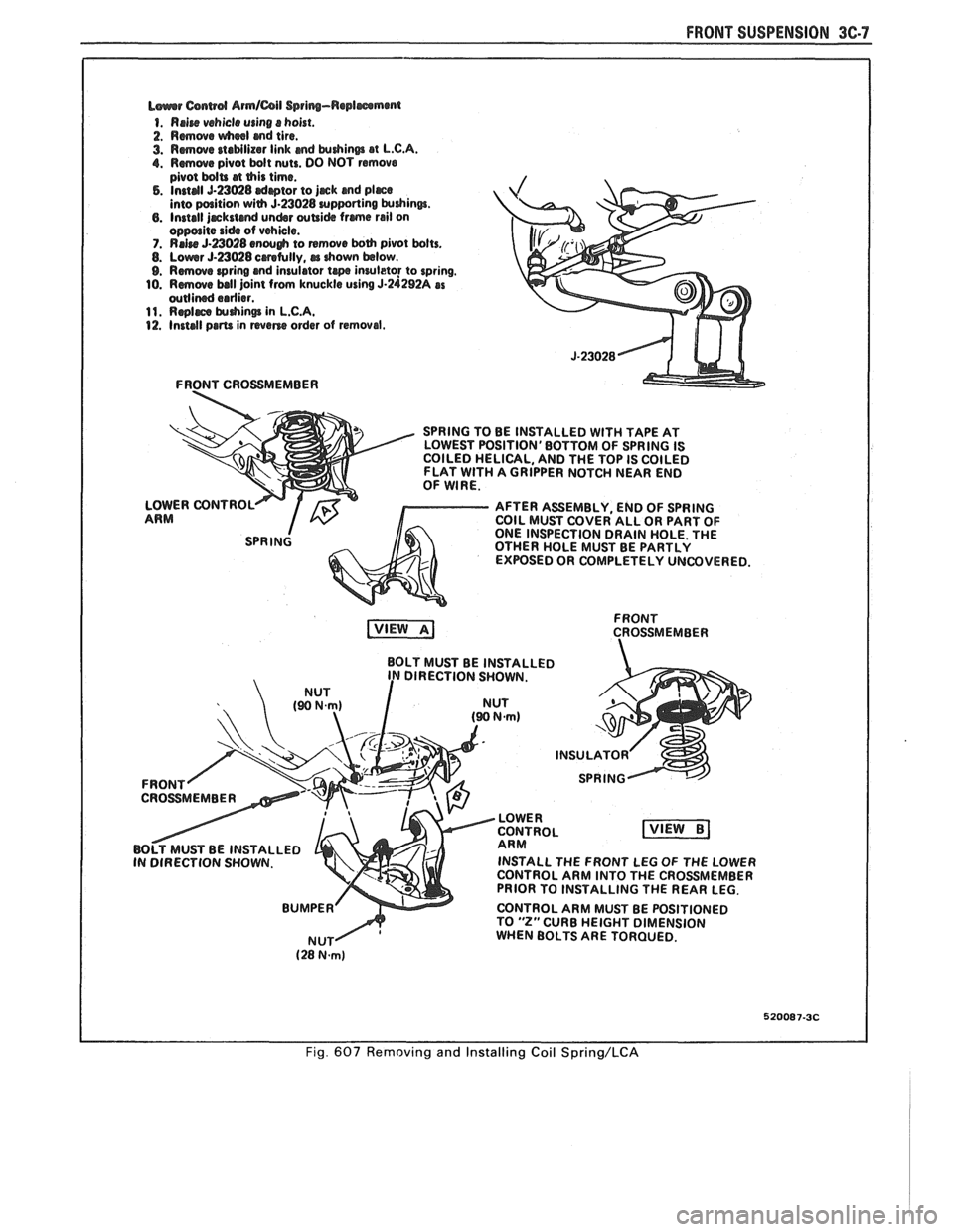
L~urrr Csnwd Armlail Spring-Replmmmt
1. Rrire vehicle using s hoist.
2. Rmwe wheel md tire.
3. Rmwe staMlizar link md krdrinm at L.C.A. 1. Rmwe pivot bdt nuts. DO NOT remove
pivot bdU at this time. 5. Instal 5-23028 drptor to jjrck and pljrce into paition with 5.23028 urpporting krdrinw. 6. Install jrckstcmd undsr wUi& frme rail on oppolite side of vehicle. 7. RrJre 5-a028 enough to remwe both pivot bolts. 8. Lowr 5-23028 crretully, rr drown below. 9. Rmove wring and insulator te inruleto! to spring.
10. Rmwe ball joint from knuckle using 5-24292A as wllined erdier. 11. Rqlrce $uhin@ in L.C.A. 12. Install prm in wane order of removal.
FRONT CROSSMEMBER
SPRING TO BE INSTALLED
WlTH TAPE AT
LOWEST POSITION'BOTTOM OF SPRING IS
COILED HELICAL, AND THE TOP IS COILED
FLAT
WlTH A GRIPPER NOTCH NEAR END
OF WIRE.
LOWER CONTROL
AFTER ASSEMBLY, END OF SPRING
ARM COIL MUST COVER ALL OR PART OF
ONE INSPECTION DRAIN HOLE. THE
OTHER HOLE MUST BE PARTLY
EXPOSED OR COMPLETELY UNCOVERED.
FRONT
CROSSMEMBER
BOLT MUST BE INSTALLED
DIRECTION SHOWN.
INSTALL THE FRONT LEG
OF THE LOWER
CONTROL ARM INTO THE CROSSMEMBER
PRIOR TO INSTALLING THE REAR LEG.
CONTROL ARM MUST BE POSITIONED
TO
"2" CURB HEIGHT DIMENSION
WHEN BOLTS ARE TORQUED.
520087-3C
Fig. 607 Removing and Installing Coil Spring/LCA
Page 222 of 1825
REAR SUSPENSION 30.1
SECTION 3D
REAR SUSPENS
NOTICE: All rear suspension fasteners are important attaching parts in that they could affect the
performance of vital parts and systems, and/or could result in major repair expense. They must be replaced with
one of the same part number or with an equivalent part if replacement becomes necessary. Do not use
a
replacement part of lesser quality or substitute design. Torque values must be used as specified during reassembly
to assure proper retention of all parts. There is to be no welding as it may result in extensive damage and weakening
of the metal.
CONTENTS
General Information ................................ 3D- 1 Rear Lower Control Arm ............................ 3D-4
Qn-Car Service ............................ .. .......... 3D- 1 Bushing (Rear Lower Control Arm) ........... 3D-4
Shock Absorbers ........................................ 3D- 1 Torque Arm .............................................. 3D-5
Coil Springs and Insulators ......................... 3D- 1 Rear Stabilizer Shaft .................................. 3D-6
Track Bar ................................................... 3D-3 Bumper (Rubber) ....................................... 3D-6
Track Bar Brace ................... .. ................. 3D-3 Torque Specifications .................................. 3D-9
GENERAL INFORMATION
The rear axle assembly is attached to the vehicle
through a link type suspension system. The axle
housing is connected to the body by two lower control
arms and a track bar. A single torque arm is used in
place of upper control arms. It is rigidly mounted to the
rear axle housing at the rear and through a rubber
bushing to the transmission at the front. Coil springs
are used to support the weight of the car, and ride
control is provided by shock absorbers mounted to the
rear of the axle housing. A stabilizer shaft is optional.
The shock absorbers are mounted at the bottom
with a bolt and nut to brackets welded to the axle
housing, and at the top to the reinforced body area with
a nut. The only service the shock absorbers require is
replacement if they
have lost tllcir resistance, are
danaged, or are leaking flldd.
ON-CAR SERVICE
SI-IOCK ABSORBERS
Fig. 602
Remove or Disconnect
1. Hoist car and support rear axle.
2. From above, pull back carpeting and remove
shock absorber upper mounting nut.
NOTICE: Axle assembly must be supported
before removing upper shock absorber nut to avoid
possible damage to brake lines, track bar and prop
shaft.
3. Loosen and remove shock absorber lower
mounting nut from shock absorber. Remove
shock.
Install or Connect
NOTICE: See NOTICE on Page 3D-1 of this
section.
1. Position shock absorber through body mounting
hole and loosely install the lower shock absorber
mounting nut.
2. From above, install the upper shock absorber
retainer and nut. Torque nut.
3. Torque lower shock absorber nut.
4. Remove rear axle support and lower car.
COIL SPRINGS AND INSULATORS
Fig. 603
Remove or Disconnect
1. Hoist car on non twin post-type hoist and support
rear axle assembly with an adjustable lifting
device.
2. Track bar mounting bolt at axle assembly.
Loosen track bar bolt at body brace.
3. Rear brake hose clip at underbody to allow
additional axle drop.
4. Right and left shock absorber lower attaching
nuts.
5. Carefully lower rear axle and remove spring(s)
and or insulator(s).
NOTICE: DO NOT suspend rear axle by brake
hose. Damage to hose could result.
Install or Connect
NOTICE: See NOTICE on Page 3D-1 of this
section.
Page 223 of 1825
3D-2 REAR SUSPENSION
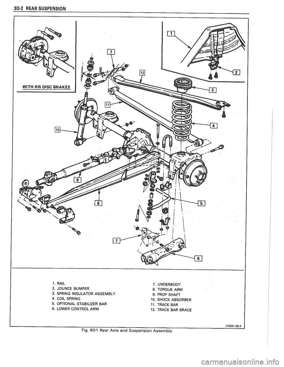
1. RAIL
2. JOUNCE BUMPER
3. SPRING INSULATOR ASSEMBLY
4, COIL SPRING
5. OPTIONAL STABILIZER BAR
6. LOWER CONTROL ARM
7. UNDERBODY
8. TORQUE ARM
9. PROP SHAFT
10. SHOCK ABSORBER
11. TRACK BAR
12. TRACK BAR BRACE
Fig.
60 1 Rear Axle and Suspension Assembly
Page 224 of 1825
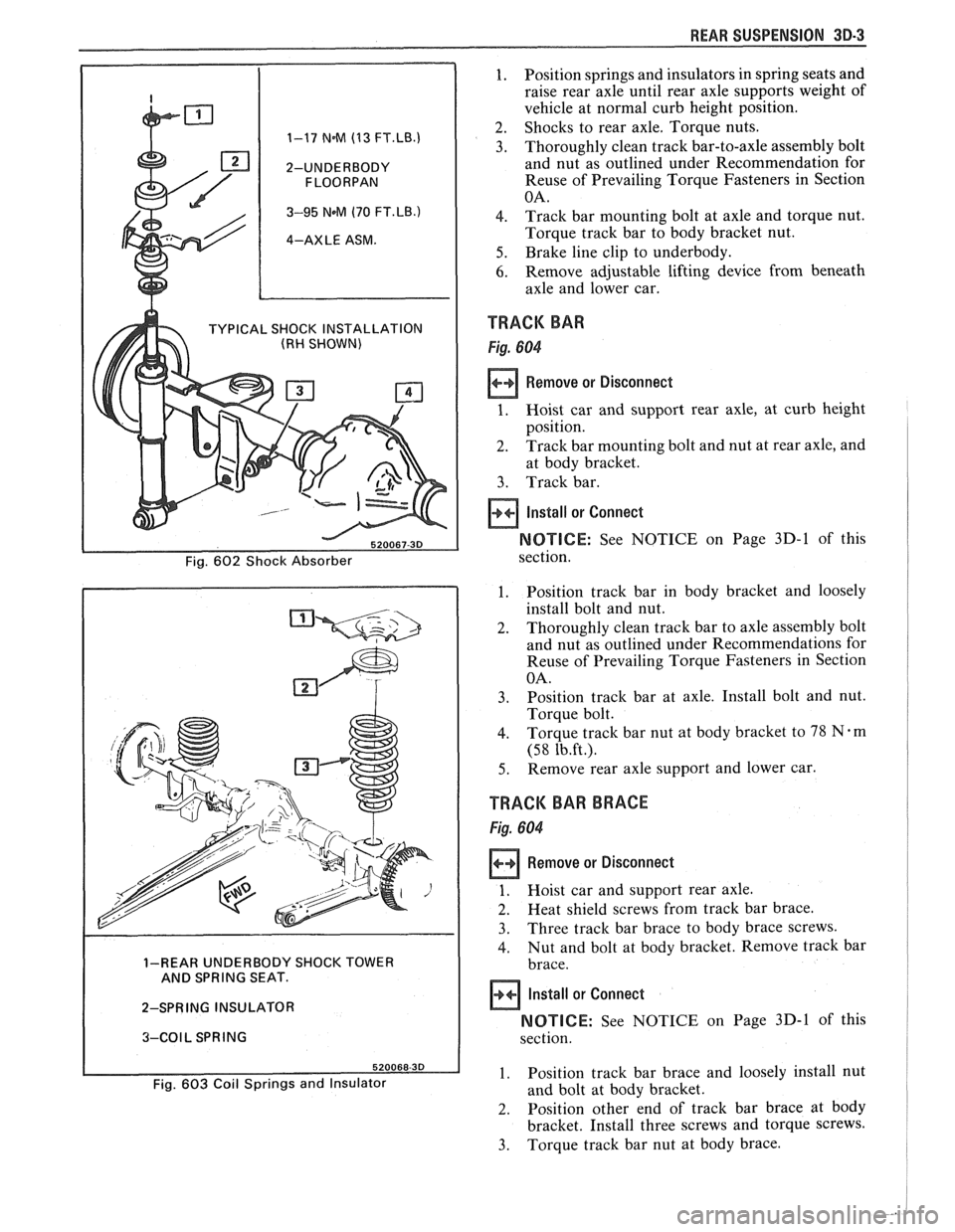
REAR SUSPENSION 30-3
1. Position springs and insulators in spring seats and
raise rear axle until rear axle supports weight of
vehicle at normal curb height position.
2. Shocks to rear axle. Torque nuts. 1-17 N.M (13 FT.LB.1 3. Thoroughly clean track bar-to-axle assembly bolt
2-UNDERBODY and nut as outlined under Recommendation for
Reuse of Prevailing Torque Fasteners in Section
3-95 NeM (70 FT.LB.) 4. Track bar mounting bolt at axle and torque nut.
4-AXLE ASM. Torque track bar to body bracket nut.
5. Brake line clip to underbody.
6. Remove adjustable lifting device from beneath
axle and lower car.
TYPICAL SHOCK INSTALLATION TRACK BAR (RH SHOWN)
Remove or Disconnect
at body bracket.
3. Track bar.
Install or Connect
NOTICE: See NOTICE on Page 3D-1 of this
1. Position track bar in body bracket and loosely
install bolt and nut.
2. Thoroughly clean track bar to axle assembly bolt
and nut as outlined under Recommendations for
Reuse of Prevailing Torque Fasteners in Section
3. Position track bar at axle. Install bolt and nut.
4. Torque track bar nut at body bracket to 78 Nem
5. Remove rear axle support and lower car.
TRACK BAR BRACE
1. Hoist car and support rear axle.
2. Heat shield screws from track bar brace.
3. Three track bar brace to body brace screws.
4. Nut and bolt at body bracket. Remove track bar 1-REAR UNDERBODY SHOCK TOWER
AND SPRING SEAT.
2-SPRING INSULATOR
NOTICE: See NOTICE on Page 3D-1 of this 3-COIL SPRING
1. Position track bar brace and loosely install nut Fig. 603 Coil Springs and Insulator and bolt at body bracket.
2. Position other end of track bar brace at body
bracket. Install three screws and torque screws.
3. Torque track bar nut at body brace.
Page 226 of 1825
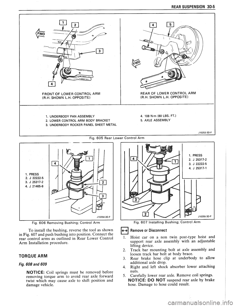
REAR SUSPENSION 3D-5
FRONT OF LOWER CONTROL ARM REAR OF
LOWER CONTROL ARM (R.W. SHOWN L.H. OPPOSITE) (R.H. SHOWN L.H. OPPOSITE)
1. UNDERBODY PAN ASSEMBLY 4. 108 N.rn (80 LBS. FT.)
2. LOWER CONTROL ARM BODY BRACKET 5. AXLE ASSEMBLY
3. UNDERBODY ROCKER PANEL SHEET METAL
Fig.
605 Rear Lower Control Arm
1. PRESS 2. J 22222-5
3.
J 25317-2
4.
J 21465-8
Fig. 606 Removing Bushing; Control Arm
To install the bushing, reverse the tool as shown
in Fig.
607 and push bushing into position. Connect the
rear control arms as outlined in Rear Lower Control
Arm Installation procedure.
TORQUE ARM
Fig. 608 and 609
NOTICE: Coil springs must be removed before
removing torque arm to avoid rear axle forward
twist which may cause axle to shift position and
damage vehicle.
1. PRESS
2. J 25317-2
3.
J 22222-5
4.
J 25317-1
I I Fig. 607 Installing Bushing; Contrcl Arm
Remove or Disconnect
1. Hoist car on a non twin post-type hoist and
support rear axle assembly with an adjustable
lifting device.
2. Track bar mounting bolt at axle assembly and
loosen track bar bolt at body brace.
3. Rear brake hose clip at underbody to allow
additional axle drop.
4. Right and left shock absorber lower attaching
nuts.
5. Carefully lower rear axle. Remove coil springs.
NOTICE: DO NOT suspend rear axle by brake
hose. Damage to hose could result.
Page 229 of 1825
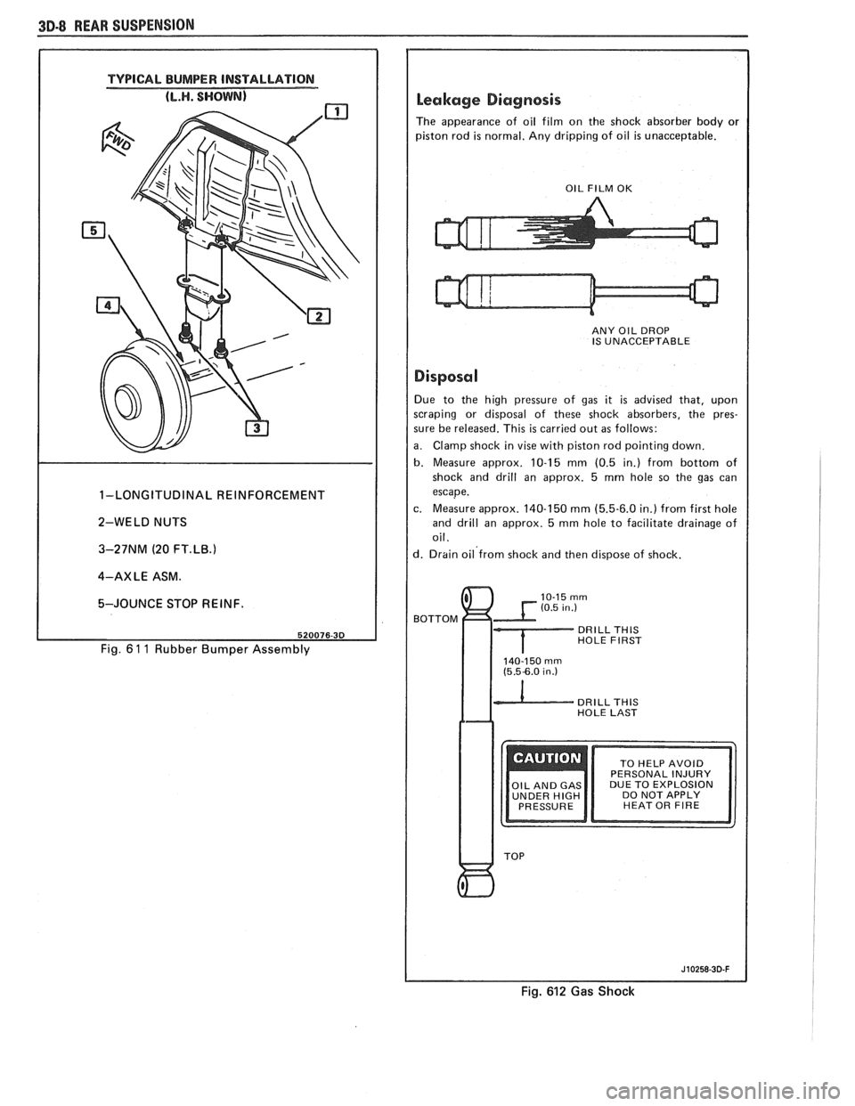
3D-8 REAR SUSPENSION
TYPICAL BUMPER INSTALLATION
1-LONGITUDINAL REINFORCEMENT
2-WELD NUTS
3-27NM (20
FT.LB.1
4-AXLE ASM.
5-JOUNCE STOP REINF.
Fig. 6 1 1 Rubber Bumper Assembly
Leakage Diagnosis
The appearance of oil film on the shock absorber body or
piston rod
is normal. Any dripping of oil is unacceptable.
I OIL FILM OK I
ANY OIL DROP
IS UNACCEPTABLE
I Disposal I Due to the high pressure of gas it is advised that, upon
scraping or disposal of these shock absorbers, the pres-
sure be released. This
is carried out as follows:
a. Clamp shock in vise with piston rod pointing down.
b. Measure approx. 10-15 mm (0.5 in.) from bottom of
shock and drill an approx. 5
mm hole so the gas can
escape.
c. Measure approx. 140-150
mm (5.5-6.0 in.) from first hole
and drill an approx. 5
mm hole to facilitate drainage of
oil.
d. Drain oil'from shock and then dispose of shock.
BOTTOM
DRILL THlS HOLE FIRST
140-150 rnrn (5.5-6.0 in.)
DRILL THlS HOLE LAST
DUE TO EXPLOSION
UNDER
HIGH DO NOT APPLY
HEAT OR FIRE
Fig. 612 Gas Shock
Page 235 of 1825
3E.4 TIRES AND WHEELS
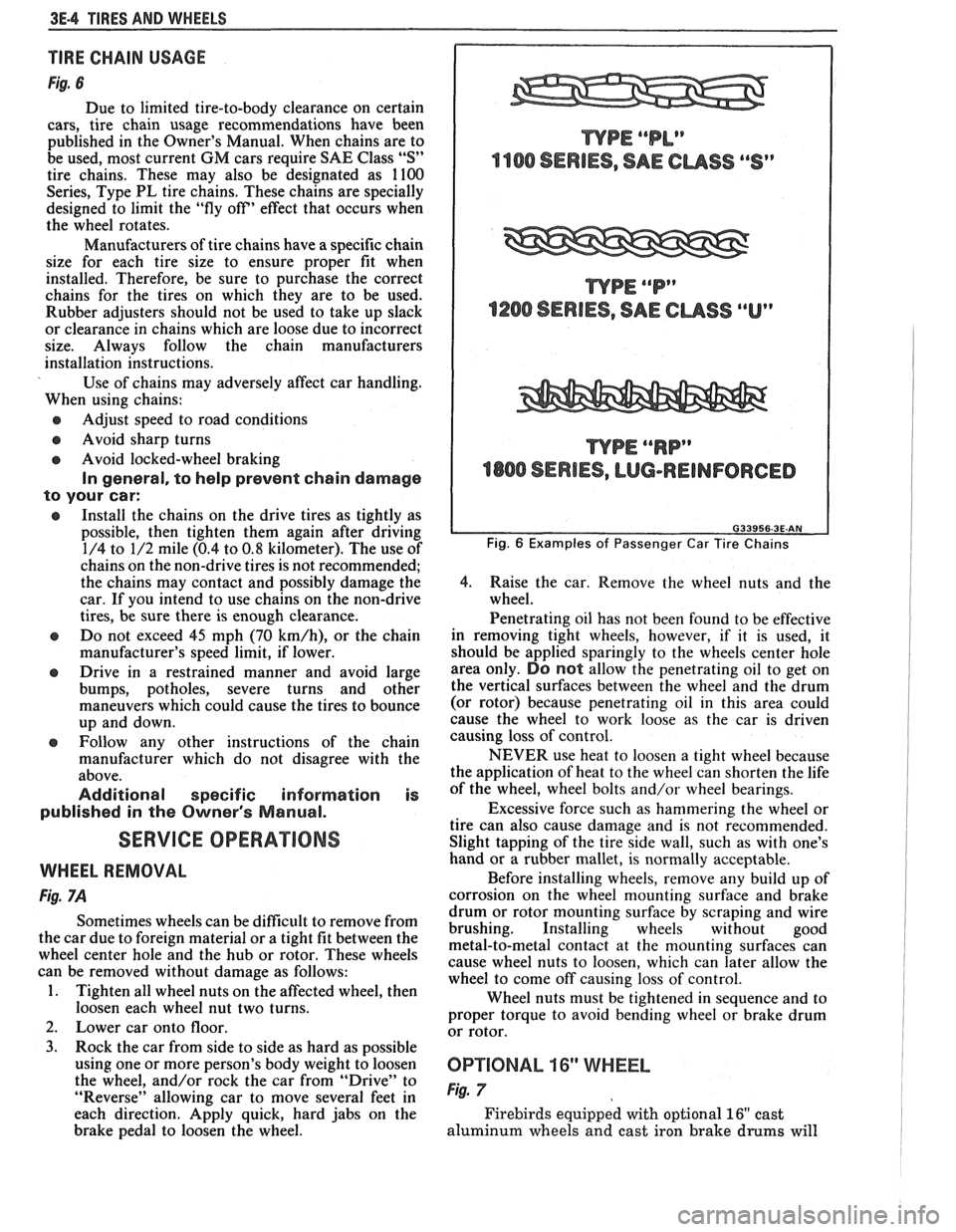
TIRE CHAIN USAGE
Fig. 6
Due to limited tire-to-body clearance on certain
cars, tire chain usage recommendations have been
published in the Owner's Manual. When chains are to
be used, most current
GM cars require SAE Class "S"
tire chains. These may also be designated as 1100
Series, Type PL tire chains. These chains are specially
designed to limit the "fly off' effect that occurs when
the wheel rotates.
Manufacturers of tire chains have a specific chain
size for each tire size to ensure proper fit when
installed. Therefore, be sure to purchase the correct
chains for the tires on which they are to be used.
Rubber adjusters should not be used to take up slack
or clearance in chains which are loose due to incorrect
size. Always follow the chain manufacturers
installation instructions.
Use of chains may adversely affect car handling.
When using chains:
@ Adjust speed to road conditions
@ Avoid sharp turns
@ Avoid locked-wheel braking
In general, to help prevent chain damage
to your car:
@ Install the chains on the drive tires as tightly as
possible, then tighten them again after driving
1/4 to 1/2 mile (0.4 to
0.8 kilometer). The use of
chains on the non-drive tires is not recommended;
the chains may contact and possibly damage the
car. If you intend to use chains on the non-drive
tires, be sure there is enough clearance.
e Do not exceed 45 mph (70 km/h), or the chain
manufacturer's speed limit, if lower.
@ Drive in a restrained manner and avoid large
bumps, potholes, severe turns and other
maneuvers which could cause the tires to bounce
up and down.
e Follow any other instructions of the chain
manufacturer which do not disagree with the
above.
Additional specific information is
published in the Owner's Manual.
SERVICE OPERATIONS
WHEEL REMOVAL
Fig. 7A
Sometimes wheels can be difficult to remove from
the car due to foreign material or a tight fit between the
wheel center hole and the hub or rotor. These wheels
can be removed without damage as follows:
1. Tighten all wheel nuts on the affected wheel, then
loosen each wheel nut two turns.
2. Lower car onto floor.
3. Rock the car from side to side as hard as possible
using one or more person's body weight to loosen
the wheel, and/or rock the car from
"Drive" to
"Reverse" allowing car to move several feet in
each direction. Apply quick, hard jabs on the
brake pedal to loosen the wheel.
WPE ""P"
1200 SERIES, SAE CUSS ""Up
WPE ""RP"
4800 SERIES, LUG-REINFORCED
Fig. 6 Examples of Passenger Car Tire Chains
4.
Raise the car. Remove the wheel nuts and the
wheel.
Penetrating oil has not been found to be effective
in removing tight wheels, however,
if it is used, it
should be applied sparingly to the wheels center hole
area only.
DO not allow the penetrating oil to get on
the vertical surfaces between the wheel and the drum
(or rotor) because penetrating oil in this area could
cause the wheel to work loose as the car is driven
causing loss of control.
NEVER use heat to loosen a tight wheel because
the application of heat to the wheel can shorten the life
of the wheel, wheel bolts and/or wheel bearings.
Excessive force such as hammering the wheel or
tire can also cause damage and is not recommended.
Slight tapping of the tire side wall, such as with one's
hand or a rubber mallet, is normally acceptable.
Before installing wheels, remove any build up of
corrosion on the wheel mounting surface and brake
drum or rotor mounting surface by scraping and wire
brushing. Installing wheels without good
metal-to-metal contact at the mounting surfaces can
cause wheel nuts to loosen, which can later allow the
wheel to come off causing loss of control.
Wheel nuts must be tightened in sequence and to
proper torque to avoid bending wheel or brake drum
or rotor.
0P"FIONAL 16" WHEEL
Fig. 7
Firebirds equipped with optional 16" cast
aluminum wheels and cast iron brake
drums will