1988 PONTIAC FIERO oil
[x] Cancel search: oilPage 302 of 1825
BRAKES 5-9
TUBE hlUST BE
SUBMERGED IN
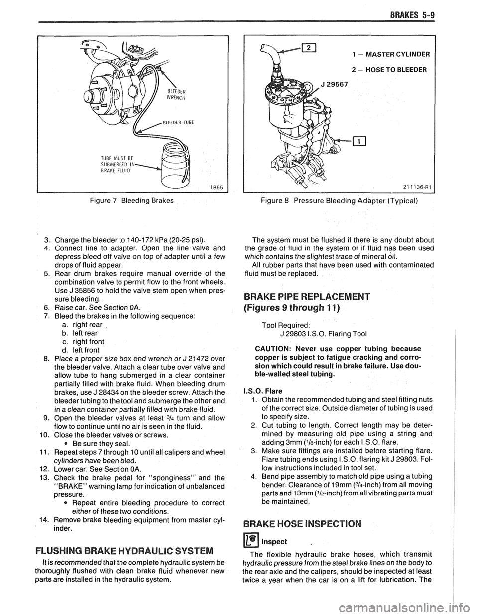
Figure 7 Bleeding Brakes
3. Charge the bleeder to 140-172
kPa (20-25 psi).
4. Connect line to adapter. Open the line valve and
depress bleed off valve on top of adapter until a few
drops of fluid appear.
5. Rear drum brakes require manual override of the
combination valve to permit flow to the front wheels. Use
J 35856 to hold the valve stem open when pres-
sure bleeding.
6. Raise car. See Section
OA.
7. Bleed the brakes in the following sequence:
a. right rear
b. left rear
c. right front
d. left front
8. Place a proper size box end wrench or
J 21472 over
the bleeder valve. Attach a clear tube over valve and
allow tube to hang submerged in a clear container
partially filled with brake fluid. When bleeding drum
brakes, use
J 28434 on the bleeder screw. Attach the
bleeder tubing to the tool and submerge the other end
in a clean container partially filled with brake fluid.
9. Open the bleeder valves at least 3/4 turn and allow
flow to continue until no air is seen in the fluid.
10. Close the bleeder valves or screws.
Be sure they seal.
11. Repeat steps
7 through 10 until all calipers and wheel
cylinders have been bled.
12. Lower car. See Section OA.
13. Check the brake pedal for "sponginess" and the
"BRAKE" warning lamp for indication of unbalanced
pressure.
* Repeat entire bleeding procedure to correct
either of these two conditions.
14. Remove brake bleeding equipment from master cyl-
inder.
FLUSHING BRAKE HYDRAULIC SYSTEM
It is recommended that the complete hydraulic system be
thoroughly flushed with clean brake fluid whenever new
parts are installed in the hydraulic system.
1 - MASTER CYLINDER
u 2 - HOSE TO BLEEDER
Figure 8 Pressure Bleeding Adapter (Typical)
The system must be flushed if there is any doubt about
the grade of fluid in the system or if fluid has been used
which contains the slightest trace of mineral oil.
All rubber parts that have been used with contaminated
fluid must be replaced.
BRAKE PIPE REPLACEMENT
(Figures
9 through 11)
Tool Required:
J 29803 I.S.O. Flaring Tool
CAUTION: Never use copper tubing because
copper is subject to fatigue cracking and corro-
sion which could result in brake failure. Use dou-
ble-walled steel tubing.
I.S.O. Flare
1. Obtain the recommended tubing and steel fitting nuts
of the correct size. Outside diameter of tubing is used
to specify size.
2. Cut tubing to length. Correct length may be deter-
mined by measuring old pipe using a string and
adding 3mm ('la-inch) for each I.S.O. flare.
3. Make sure fittings are installed before starting flare.
Flare tubing ends using I.S.O. flaring kit
J 29803. Fol-
low instructions included in tool set.
4. Bend pipe assembly to match old pipe using a tubing
bender. Clearance of
19mm (314-inch) from all moving
parts and
13mm (lh-inch)from all vibrating parts must
be maintained.
BRAKE HOSE INSPECTION
0 inspect
The flexible hydraulic brake hoses, which transmit
hydraulic pressure from the steel brake lines on the body to
the rear axle and the calipers, should be inspected at least
twice a year when the car is on a lift for lubrication. The
Page 313 of 1825
5A3-2 COMPOSlf E MASTER CYLINDER
GENERAL DESCRIPTION
This master cylinder is a composite design
(plastic reservoir and aluminum bore) incorporating
a
conventional front to rear brake system split. The
primary piston provides the fluid pressure to the front
brakes, while the secondary piston provides the fluid
pressure to the rear brakes. If pressure is lost from
either system, the remaining system will function to
stop the vehicle.
A quick take-up feature is incorporated which
provides a large volume of fluid to the wheel brakes at
low pressure with initial brake apply. The low pressure
fluid quickly provides the displacement requirements
created by the seal retraction of the pistons into the
front calipers.
Important
e Replace all components included in repair kits
used to service this master cylinder.
e Lubricate rubber parts with clean brake fluid to
ease assembly.
a Do not use lubricated shop air on brake parts as
damage to rubber components may result.
e If any hydraulic component is removed or
disconnected, it may be necessary to bleed all or
part of the brake system.
e The torque values specified are for dry,
unlubricated fasteners.
a Perform service operations on a clean bench free
from all mineral oil materials.
ON-CAR SERVICE
MASTER CYLINDER ASSEMBLY
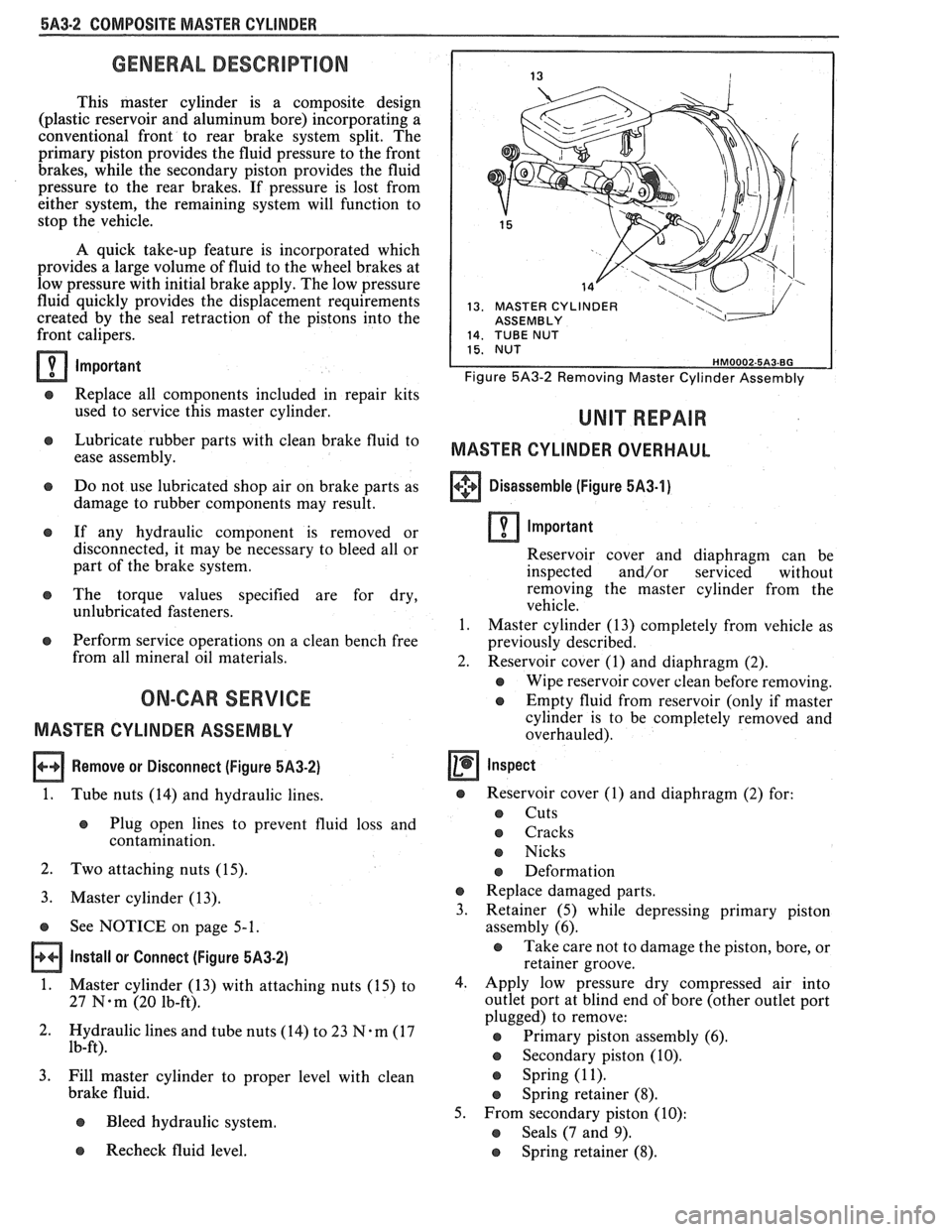
Remove or Disconnect (Figure 5,432)
1.
Tube nuts (14) and hydraulic lines.
e Plug open lines to prevent fluid loss and
contamination.
2. Two attaching nuts (15).
3. Master cylinder (13).
s See NOTICE on page 5-1.
Install or Connect (Figure 5A3-2)
1.
Master cylinder (13) with attaching nuts (15) to
27
N-m (20 lb-ft).
2. Hydraulic lines and tube nuts
(14) to 23 7%-m (17
lb-ft).
3. Fill master cylinder to proper level with clean
brake fluid.
e Bleed hydraulic system.
13. MASTER CYLINDER I ASSEMBLY
Figure 5A3-2 Removing Master Cylinder Assembly
MASTER CYLINDER OVERHAUL
+++ Disassemble (Figure 5A3-1) [I]
Important
Reservoir cover and diaphragm can be
inspected and/or serviced without
removing the master cylinder from the
vehicle.
1. Master cylinder (13) completely from vehicle as
previously described.
2. Reservoir cover (1) and diaphragm (2).
e Wipe reservoir cover clean before removing.
e Empty fluid from reservoir (only if master
cylinder is to be completely removed and
overhauled).
Inspect
s Reservoir cover (I) and diaphragm (2) for:
s Cuts
o Cracks
e Nicks
e Deformation
e Replace damaged parts.
3. Retainer
(5) while depressing primary piston
assembly (6).
e Take care not to damage the piston, bore, or
retainer groove.
4. Apply low pressure dry compressed air into
outlet port at blind end of bore (other outlet port
plugged) to remove:
@ Primary piston assembly (6).
s Secondary piston (10).
s Spring (1 1).
e Spring retainer (8).
5. From secondary piston (10):
e Seals (7 and 9).
Recheck fluid level. e Spring retainer (8).
Page 317 of 1825
SBO-2 DISC BRAKE CALIPER ASSEMBLY
GENERAL DESCRIP"F0N
This caliper has a single bore and is mounted to
the support bracket with two mounting bolts.
Hydraulic pressure, created by applying the brake
pedal, is converted by the caliper to a stopping force.
This force acts equally against the piston and the
bottom of the caliper bore to move the piston outward
and to move (slide) the caliper inward resulting in a
clamping action on the rotor. This clamping action
forces the linings against the rotor, creating friction to
stop the vehicle.
Important
e Replace all components included in repair kits
used to service this caliper.
Lubricate rubber parts with clean brake fluid to
ease assembly.
e Do not use lubricated shop air on brake parts as
damage to rubber components may result.
e If any hydraulic component is removed or
disconnected, it may be necessary to bleed all or
part of the brake system.
Replace shoe and linings in axle sets only.
e The torque values specified are for dry,
unlubricated fasteners.
s Perform service operations on a clean bench free
from all mineral oil materials.
ON-GAR SERVICE
CALIPER ASSEMBLY
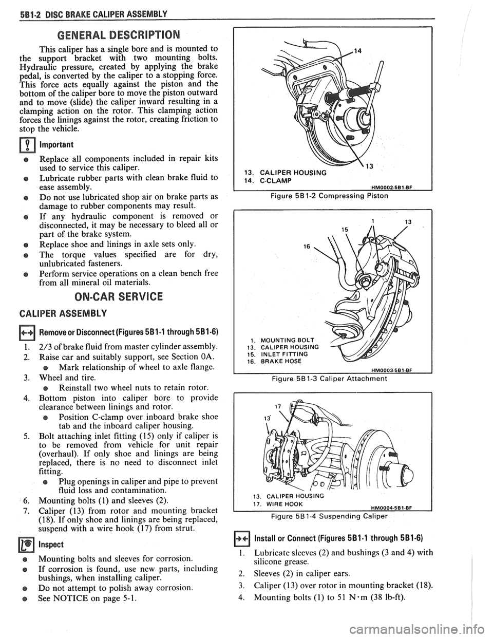
Removesr Disconnect (Figures 581-1 through 581-6)
1. 2/3 of brake fluid from master cylinder assembly.
2. Raise car and suitably support, see Section OA.
Mark relationship of wheel to axle flange.
3. Wheel and tire.
Reinstall two wheel nuts to retain rotor.
4. Bottom piston into caliper bore to provide
clearance between linings and rotor.
e Position C-clamp over inboard brake shoe
tab and the inboard caliper housing.
5. Bolt attaching inlet fitting (15) only if caliper is
to be removed from vehicle for unit repair
(overhaul). If only shoe and linings are being
replaced, there is no need to disconnect inlet
fitting.
e Plug openings in caliper and pipe to prevent
fluid loss and contamination.
6. Mounting bolts (1) and sleeves (2).
7. Caliper (13) from rotor and mounting bracket
(18). If only shoe and linings are being replaced,
suspend with a wire hook (17) from strut.
Inspect
@ Mounting bolts and sleeves for corrosion.
@ If corrosion is found, use new parts, including
bushings, when installing caliper.
e Do not attempt to polish away corrosion.
See NOTICE on page 5-1.
," 13. CALIPER HOUSING
Figure
58 1-2 Compressing Piston
16
MOUNTING BOLT CALIPER HOUSING INLET FITTING BRAKE HOSE
Figure 58 1-3 Caliper Attachment
13. CALIPER HOUSING
Figure 5B1-4 Suspending Caliper
Install or Connect (Figures 581.1 through 581-6)
1.
Lubricate sleeves (2) and bushings (3 and 4) with
silicone grease.
2. Sleeves (2) in caliper ears.
3. Caliper (13) over rotor in mounting bracket
(18).
4. Mounting bolts (1) to 51 N-m (38 lb-ft).
Page 323 of 1825
586.2 DISC BRAKE CALIPER ASSEMBLY
GENERAL DESCRIPUON
This caliper has a single bore and is mounted to
the support bracket with two mounting bolts.
Hydraulic pressure, created by applying force to the
brake pedal, is converted by the caliper to a stopping
force. This force acts equally against the piston and the
bottom of the caliper bore to move the piston outward
and to move (slide) the caliper inward resulting in a
clamping action on the rotor. This clamping action
forces the linings against the rotor, creating friction to
stop the vehicle.
When the parking brake is applied, the lever turns
the actuator screw which is threaded into a nut in the
piston assembly. This causes the piston to move
outward and the caliper to slide inward mechanically,
forcing the linings against the rotor. The piston
assembly contains a self-adjusting mechanism to keep
the parking brake in proper adjustment.
NOTICE: Replace all components included in
repair kits used to service this caliper. Lubricate
rubber parts with clean brake fluid to ease
assembly. Do not
uhe lubricated shop air on brake
parts as damage to rubber components may result.
If any hydraulic
coniponent is removed or
disconnected,
it may he necessary to bleed all or
part of the brake system. Replace shoe and linings
in axle sets only. The torque values specified are
for dry,
unlubricated fasteners. Perform service
operations
011 a clean bench free from all mineral
oil materials.
ON-CAR SERVICE
CALIPER ASSEMBLY
Figures 2 thru 4
Remove or Disconnect
1. 2/3 of brake fluid from master cylinder assembly.
2. Raise car and suitably support.
e Mark relationship of wheel at axle flange.
3. Wheel and tire.
e Reinstall two lug liuts to retain rotor.
4. Loosen tension on parking brake cable at
equalizer.
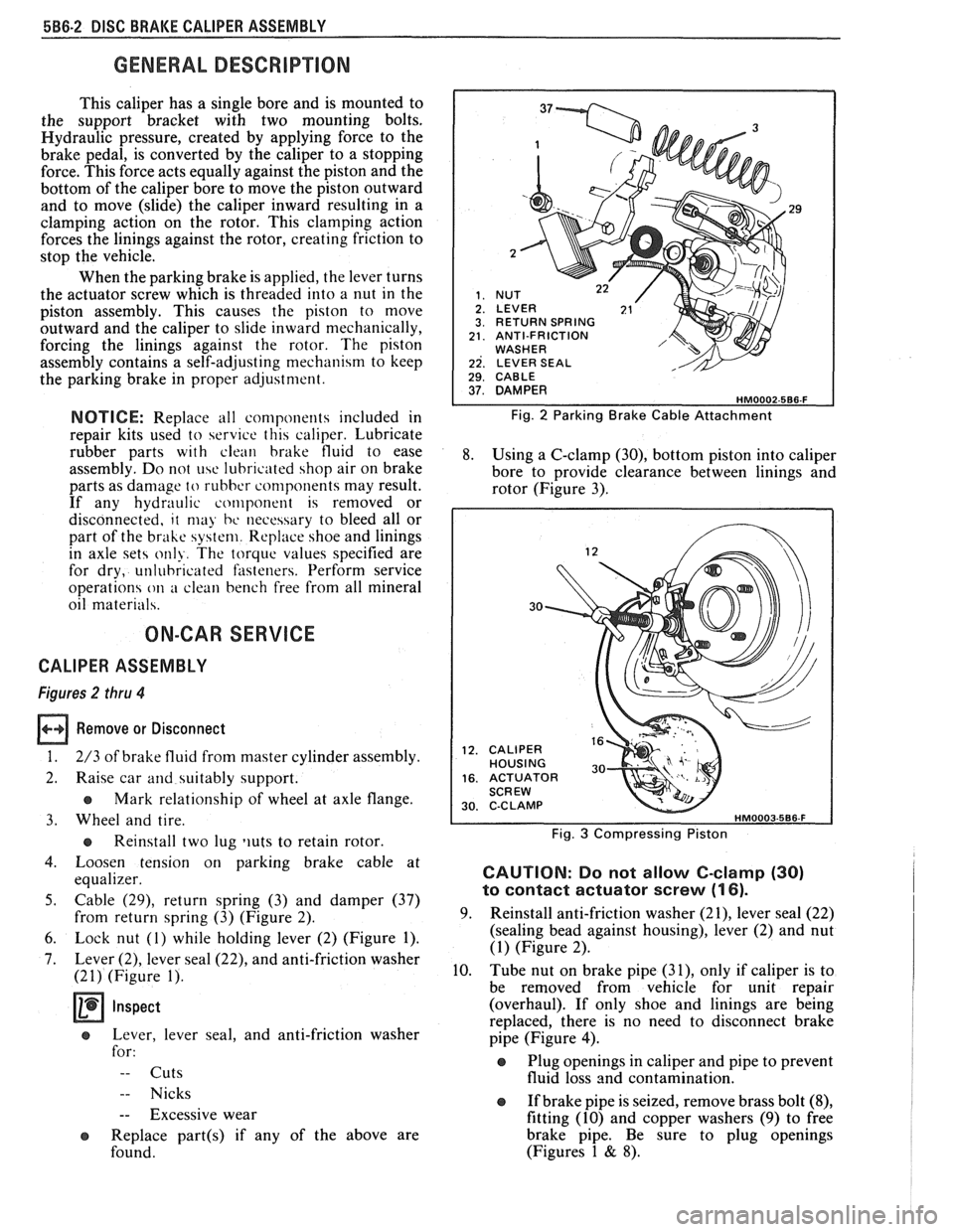
5. Cable (29), return spring (3) and damper (37)
from return spring (3) (Figure 2).
6. Lock nut (1) while holding lever (2) (Figure 1).
7. Lever (2), lever seal (22), and anti-friction washer
(21) (Figure 1).
Inspect
e Lever, lever seal, and anti-friction washer
for:
-- Cuts
-- Nicks
-- Excessive wear
e Replace part(s) if any of the above are
found.
29
RETURN SPRING ANTI-FRICTION WASHER LEVER SEAL 1 29. CABLE I
Fig. 2 Parking Brake Cable Attachment
8. Using a C-clamp (30), bottom piston into caliper
bore to provide clearance between linings and
rotor (Figure 3).
30
CALIPER HOUSING ACTUATOR SCREW C-C LAMP
Fig. 3 Compressing Piston
CAUTION: Do not allow C-clamp (30)
to contact actuator screw (1 6).
9. Reinstall anti-friction washer (21), lever seal (22)
(sealing bead against housing), lever (2) and nut
(1) (Figure 2).
10. Tube nut on brake pipe
(31), only if caliper is to
be removed from vehicle for unit repair
(overhaul). If only shoe and linings are being
replaced, there is no need to disconnect brake
pipe (Figure
4).
Plug openings in caliper and pipe to prevent
fluid loss and contamination.
If brake pipe is seized, remove brass bolt
(8),
fitting (10) and copper washers (9) to free
brake pipe. Be sure to plug openings
(Figures 1
& 8).
Page 329 of 1825
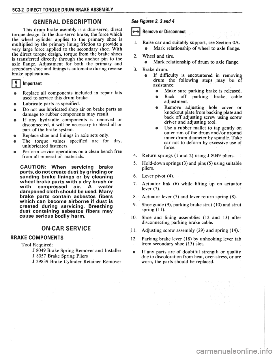
5C3-2 DIRECT TORQUE DRUM BRAKE ASSEMBLY
GENERAL DESCRIPTION
This drum brake asembly is a duo-servo, direct
torque design. In the duo-servo brake, the force which
the wheel cylinder applies to the primary shoe is
multiplied by the primary lining friction to provide a
very large force applied to the secondary shoe. With
the direct torque design, torque from the brake shoes
is transferred directly through the anchor pin to the
axle flange. Adjustment for both the primary and
secondary shoe and linings is automatic during reverse
brake applications.
Important
a Replace all components included in repair kits
used to service this drum brake.
a Lubricate parts as specified.
e Do not use lubricated shop air on brake parts as
damage to rubber components may result.
a If any hydraulic components is removed or
disconnected, it will be necessary to bleed all or
part of the brake system.
s Replace shoe and linings in axle sets only.
e The torque values specified are for dry,
unlubricated fasteners.
e Perform service operations on a clean bench free
from all mineral oil materials.
CAUTION: When servicing brake
parts, do not create dust by grinding or
sanding brake linings or by cleaning
wheel brake parts with a dry brush or
with compressed air.
A water
dampened cloth should be used.
Many
brake parts contain asbestos fibers
which can become airborne if dust is
created during servicing. Breathing
dust containing asbestos fibers may
cause serious bodily harm.
ON-CAR SERVICE
BRAKE COMPONENTS
Tool Required:
J 8049 Brake Spring Remover and Installer
J 8057 Brake Spring Pliers
J 29839 Brake Cylinder Retainer Remover
See Figures 2,3 and 4
Remove or Disconnect
1.
Raise car and suitably support, see Section OA.
e Mark relationship of wheel to axle flange.
2. Wheel and tire.
e Mark relationship of drum to axle flange.
3. Brake drum.
a If dificulty is encountered in removing
drum the following steps may be of
assistance:
@ Make sure parking brake is released.
a Back off parking brake cable
adjustment.
a Remove adjusting hole cover or
knockout plate from backing plate and
back off adjusting screw using screw
driver and adjusting tool.
a Use a rubber mallet to tap gently on
outer rim of the drum and/or around
inner drum diameter by spindle. Take
car not to deform by excessive use of
force.
4. Return springs (1 and 2) using
J 8049 pliers.
5. Hold-down springs (3) and pins (5) using suitable
pliers.
6. Lever pivot (4).
7. Actuator link (6) while lifting up on actuator
lever
(7).
8. Actuator lever (7) and lever return spring (8).
9.
Shoe guide (9), parking brake strut (10) and strut
spring
(1 1).
10. Shoe and lining assemblies (12 and 13) after
disconnecting parking brake cable.
11. Adjusting screw assembly (29) and spring (14).
12. Parking brake lever (18) by unhooking lever tab
from secondary shoe (13) slot.
e If any parts are of doubtful strength or quality
due to discoloration from heat, over-stress, or are
worn, the parts should be replaced.
Page 337 of 1825
582.2 POWER HEAD ASSEMBLY
GENERAL DESCRIPTION
This booster is a tandem vacuum suspended unit.
In a normal operating mode, with the service brakes in
the released position, the tandem vacuum suspended
booster operates with vacuum on both sides of its
diaphragms. When the brakes are applied, air at
atmospheric pressure is admitted to one side of each
diaphragm to provide the power assist. When the
service brake is released, the atmospheric air is shut off
from the one side of each diaphragm. The air is then
drawn from the booster through the vacuum check
valve to the vacuum source.
important
e Replace all components included in repair kits
used to service this booster.
e Lubricate rubber parts with silicone grease,
provided in kits, to ease assembly.
o Do not use lubricated shop air on brake parts as
damage to rubber parts may result.
o If any hydraulic component is removed or
disconnected, it may be necessary to bleed all or
part of the brake system.
e The torque values specified are for dry,
unlubricated fasteners.
Perform service operations on a clean bench free
from all mineral oil materials.
ON-CAR SERVICE
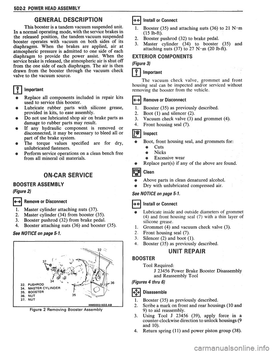
BOOSTER ASSEMBLY
(Figure 2)
Remove or Disconnect
1. Master cylinder attaching nuts (37).
2. Master cylinder (34) from booster (35).
3. Booster pushrod (32) from brake pedal.
4. Booster attaching nuts (36) and booster (35).
See NOTICE on page 5 1.
MASTER CYLINDER
BOOSTER
NUT
BOOSTER
Figure 2 Removing Booster Assembly
Install
or Connect
1, Booster (35) and attaching nuts (36) to 21 N*m
(15 lb-ft).
2. Booster pushrod (32) to brake pedal.
3. Master cylinder (34) to booster (35) and
attaching nuts (37) to
27 N-m (20 lb-ft).
EXTERIOR COMPONENTS
(Figure 3)
Important
The vacuum check valve, grommet and front
housing seal can be inspected and/or serviced without
removing the booster from the vehicle.
Remove or Disconnect
1. Booster (35)
as previously described.
2. Boot (1) and silencer (2).
3. Vacuum check
valve (3) and grommet (4).
4. Front housing seal (7).
Inspect
e Boot, front housing seal, and grommets for:
s Cuts
s Nicks
s Excessive wear
e Replace part(s) if any of the above are found.
Above parts in clean denatured alcohol.
Dry with unlubricated compressed air.
See NOTICE on page 5-1.
Install or Connect
e Lubricate inside and outside diameters of grommet
(4) and front housing seal
(7) with a thin layer of
silicone grease.
1. Grommet (4) and vacuum check valve (3).
2. Front housing seal (7).
3. Silencer (2) and boot (1).
4. Booster (35) as previously described.
UNIT REPAIR
BOOSTER
Tool Required:
J 23456 Power Brake Booster Disassembly
and Reassembly Tool
(Figures 4 thru 6)
Disassemble
1. Booster (35) as previously described.
2. Scribe a mark on front and rear housings (10 and
9) to aid reassembly.
3. Using Tool
J 23456 (39), apply force in a
counter-clockwise direction to unlock housings
(9
and 10).
4. Return spring
(1 1) and power piston group (38).
Page 346 of 1825
ENGINE GENERAL INFORMATION 6-1
SECTION 6
NE GENERAL NFORMAT
Description ............................................................... 6 TBI ...................................... .. ...... 6E2 ................ Engine Mechanical Multi Port Fuel Injection (MPFI) 6E3 -
............................................... 2.8L V-6 ....................................................... 6A2 Exhaust Systems 6F
5.OL V-8 ......................................................... 6A3 ~~~~~~l ~~f~~~~ti~~ ..................................... 6-2
............................ Engine Cooling ...................................................... 6B Engine Performance Diagnosis 6-3 ............................. Engine Fuel 6C Engine Mechanical Diagnosis
6-3 ........................................................... ................................... Engine Knock Diagnosis 6-4
Engine Electrical ................................................... 6D Compression Test ...................................... ... 6-5
................... Driveability and Emission Controls ...................... 6E Oil Leak Detection .. ..................... 6-5
ALL NEW GENERAL MOTORS VEHICLES ARE CERTIFIED BY THE UNITED STATES
ENVIRONMENTAL PROTECTION AGENCY AS CONFORMING TO THE REQUIREMENTS OF
THE REGULATIONS FOR THE CONTROL OF AIR POLLUTION FROM NEW MOTOR VEHICLES.
THlS CERTIFICATION IS CONTINGENT ON CERTAIN ADJUSTMENTS BEING SET TO
FACTORY STANDARDS. IN MOST CASES, THESE ADJUSTMENT POINTS EITHER HAVE
BEEN PERMANENTLY SEALED AND/OR MADE INACCESSIBLE TO PREVENT
INDISCRIMINATE OR ROUTINE ADJUSTMENT IN THE FIELD. FOR
THlS REASON, THE
FACTORY PROCEDURE FOR TEMPORARILY REMOVING PLUGS, CAPS, ETC., FOR
PURPOSES OF SERVICING THE PRODUCT MUST BE STRICTLY FOLLOWED AND,
WHEREVER PRACTICABLE, RETURNED TO THE ORIGINAL INTENT OF THE DESIGN.
DESCRIPTION OF: SECTION 6
SECTION 6A - ENGINE MECHANICAL used for each carburetor. TBI units are described in
This section general contains information on the Section 6E.
mechanical parts of the engine, such as block,
crankshaft, pistons, valve train, and camshaft, that are
common to most engines. Overhaul procedures,
removal and replacement procedures, and
s~ecifications are also covered. Subsections furnish
detailed information on each specific engine. Service
SECTION 6D - ENG l N E ELECTRICAL
information is also given that relates to that engine's
use in each
Carline. Specific subsections are: Items
covered in this section are battery,
generator, starter, primary and secondary ignition,
6A2
- 2.8L V-6 Engine
engine wire harness, spark plugs and wires, and
6A3
- 5.OL V-8 Engine
ignition switch.
SECTION 6B - ENGINE COOLING
Engine cooling system components such as
radiator, water pump, thermostat, and cooling fan, are
covered in this section. Accessory drive belts are also
covered, along with cooling system capacities.
SECTION 6C - FUEL SYSTEM
This section contains information on all the parts
of the fuel system
except the carburetor, or Throttle
Body Injection unit (TBI) itself. Items covered are fuel
tank, fuel pump, and fuel lines. Specific subsections are
SECTION 6E - DRIVEABILITY AND EMISSIONS
This section covers emission control systems
general information, and diagnostic procedures which
will lead to repairing performance and driveability
related problems for gasoline engine equipped vehicles.
All emission components are covered, as well as all
removal and replacement procedures. Instructions on
use of special tools are also given. Specific sections are:
6E
- Driveability and Emissions
6E2
- Fuel Injection (TBI)
Page 347 of 1825
6-2 ENGINE GENERAL INFORMATION
6E3 - Fuel Injection (Ported) This section has information
on all exhaust
system parts, such as tailpipes, mufflers, and the
SECTION 6F - EXHAUST SYSTEM catalytic converter.
GENERAL INFORMAflION
CLEANLINESS AND CARE
An automobile engine is a combination of many
machined, honed, polished and lapped surfaces with
tolerances that are measured in the ten-thousandths of
an inch. When any internal engine parts are serviced,
care and cleanliness are important. A liberal coating of
engine oil should be applied to friction areas during
assembly, to protect and lubricate the surfaces on
initial operation. Throughout this section, it should be
understood that proper cleaning and protection of
machined surfaces and friction areas is part of the
repair procedure. This is considered standard shop
practice, even if not specifically stated. PREVENTING
DAMAGE AND IN
CONTRIBUTING TO RELIABLE ENGINE
PERFORMANCE.
When raising or supporting the engine for any
reason, do not use a jack under the oil pan. Due to the
small clearance between the oil pan and the oil pump
screen, jacking against the oil pan may cause it to be
bent against the pump screen resulting in a damaged
oil pick-up unit.
When working on the engine, remember that the
12-volt electrical system is capable of causing short
circuits. When performing any work where electrical terminals could possibly be grounded, the ground cable
of the battery should be disconnected at the battery.
Any time the carburetor or air cleaner is
train components are removed removed, the intake opening should be covered. This for service, they should be in order' will protect against entrance of foreign be installed in the same locations, and with the same material, which could follow the intake passage into mating surfaces, as when removed
the cylinder and cause extensive damage when the -
Battery cables should be disconnected before any engin; is started.
major work is performed on the engine. Failure to IN THE MECHANICAL PROCEDURES
disconnect cables may result in damage to wire harness DESCRIBED IN THIS SECTION, GENERALLY
or other electrical parts. NO
REFERENCES WILL BE MADE TO THE
REMOVAL OF OPTIONAL EQUIPMENT SUCH
ENGINE SERVICE AS POWER STEERING PUMP, AIR
CONDITIONING COMPRESSOR, ETC.
THE FOLLOWING INFORMATION ON SHOULD IT BECOME NECESSARY TO
ENGINE SERVICE SHOULD BE NOTED REMOVE ANY SUCH ITEM TO
PERFORM
CAREFULLY, AS IT IS IMPORTANT IN OTHER SERVICE, REFER TO THE
APPROPRIATE SECTION OF THIS SERVICE
MANUAL FOR SPECIFIC INFORMATION.
ENGINE PERFORMANCE DIAGNOSIS
INTRODUCTION interchangeably for so long, it was necessary to decide
on the most common usage and then define them. If the
Engine Performance procedures are definition is not understood, and the exact Symptom is
guides that will lead to the most probable causes of not used, the Diagnostic procedure will not work. engine performance complaints. They cover the
components of the fuel, ignition, and mechanical It
is important to keep two facts in mind:
systems that could cause a particular
complaint, and 1. The procedures are written to diagnose problems
then outline repairs in a logical sequence. on cars
that have
"run well at one time" and
that time and wear have created the condition.
It is important to determine if the
"Service ~~~i~~ soon- light is "ON,~' or has come for 2. All possible causes cannot be covered,
a short interval while driving. If the
"Service Engine particularly with regard to emission controls. If
Soon" light has come "ON," the Computer doing the work prescribed does not correct the
Command Control System or DECS should be complaint, then either the wrong Symptom was
checked for stored
"Trouble Codes" (See Diagnostic used, or a more detailed analysis will have to be
Circuit Check, Section 6E, for the engine you are made.
working on) which may indicate the cause for the All of the Symptoms can be caused by worn out
performance
complaint.Each Symptom is defined, and or defective parts such as Spark Plugs, Ignition
it is important that the correct one be selected, based Wiring, etc. If time and/or mileage indicate that
on the complaints reported or found. The definition of parts should be replaced, it is recommended that
each symptom is included with the symptom. it
be done.
The words used may not be what you are used to Refer to:
in all cases, but because these terms have been used
@ Section 6E - Driveability and Emissions