1988 PONTIAC FIERO oil
[x] Cancel search: oilPage 283 of 1825
48-10 REAR AXLE
6. Remove oil seal by driving it out of carrier with
a blunt chisel. Do not damage carrier. Discard
seal,
7. Examine seal surface of pinion flange for tool
marks, nicks, or damage. If damaged, replace
flange as outlined under Pinion Flange
Replacement.
8. Examine carrier bore and remove any burrs that
might cause leaks around the O.D. of the seal.
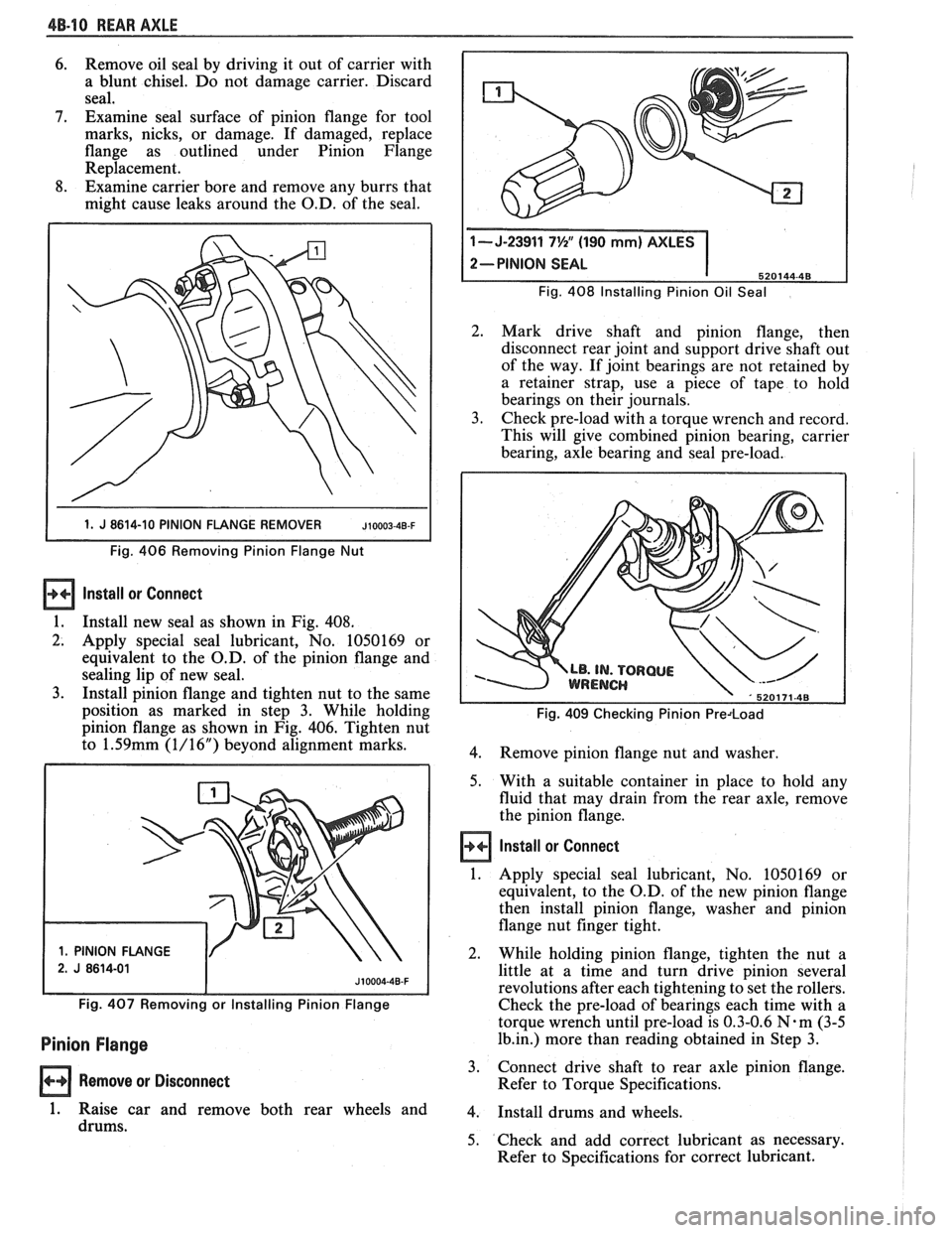
1 1. J 8614-10 PINION FLANGE REMOVER JIOOO~-~B-F I
Fig. 406 Removing Pinion Flange Nut
Install ar Connect
1.
Install new seal as shown in Fig. 408.
2. Apply special seal lubricant, No. 1050169 or
equivalent to the O.D. of the pinion flange and
sealing lip of new seal.
3. Install pinion flange and tighten nut to the same
position as marked in step 3. While holding
pinion flange as shown in Fig. 406. Tighten nut
to
1.59mm (1/16") beyond alignment marks.
1. PINION FLANGE Fig.
408 Installing Pinion
Oil Seal
2. Mark drive shaft and pinion flange, then
disconnect rear joint and support drive shaft out
of the way. If joint bearings are not retained by
a retainer strap, use a piece of tape to hold
bearings on their journals.
3. Check pre-load with a torque wrench and record.
This will give combined pinion bearing, carrier
bearing, axle bearing and seal pre-load.
Fig. 409 Checking Pinion Predoad
4.
Remove pinion flange nut and washer.
5. With a suitable container in place to hold any
fluid that may drain from the rear axle, remove
the pinion flange.
Install or Connect
1. Apply special seal lubricant, No. 1050169 or
equivalent, to the O.D. of the new pinion flange
then install pinion flange, washer and pinion
flange nut finger tight.
2. While holding pinion flange, tighten the nut a
little at a time and turn drive pinion several
revolutions after each tightening to set the rollers.
Fig. 407 Removing or Installing Pinion Flange Check the pre-load of bearings each time with a
torque wrench until pre-load is 0.3-0.6
N-m (3-5
Pinion Flange 1b.in.) more than reading obtained in Step 3.
Remove or Disconnect 3.
Connect drive shaft to rear axle pinion flange.
Refer to Torque Specifications.
1. Raise car and remove both rear wheels and 4. Install drums and wheels.
drums. 5. Check and add correct lubricant as necessary.
Refer to Specifications for correct lubricant.
Page 286 of 1825
REAR AXLE 48-13
2. Drive
pinion oil seal from carrier and remove
front pinion bearing. If the bearing is to be
replaced, remove outer race from carrier.
3. If rear pinion bearing is to be replaced remove
outer race from carrier using a punch in slots
provided for this purpose.
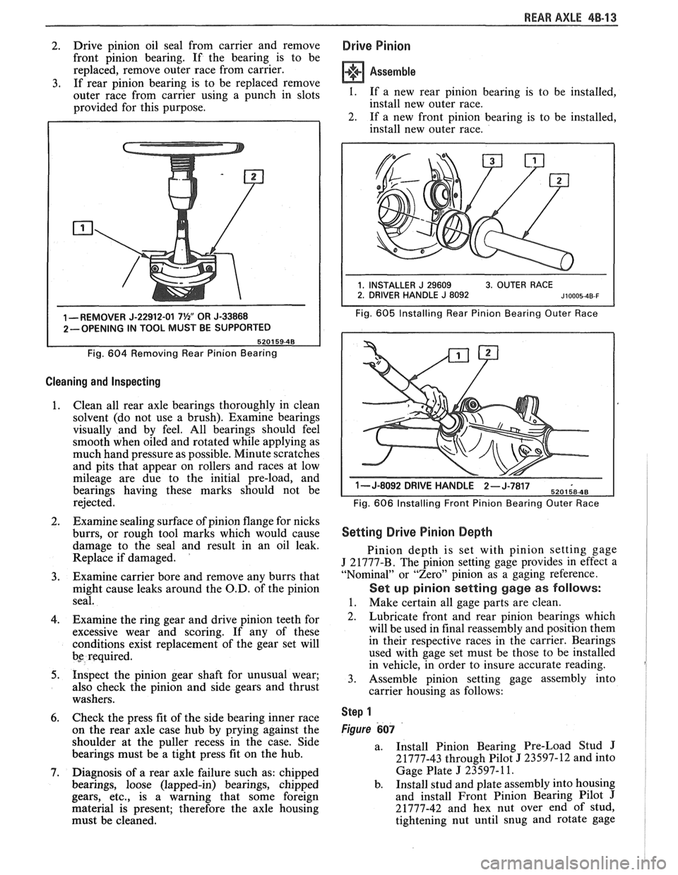
1 -REMOVER J-22912-01 7%" OR J-33868
2-OPENING IN TOOL MUST BE SUPPORTED
Fig.
604 Removing Rear Pinion Bearing
Cleaning and Inspecting
1. Clean
all rear axle bearings thoroughly in clean
solvent (do not use a brush). Examine bearings
visually and by feel. All bearings should feel
smooth when oiled and rotated while applying as
much hand pressure as possible. Minute scratches
and pits that appear on rollers and races at low
mileage are due to the initial pre-load, and
bearings having these marks should not be
rejected.
2. Examine sealing surface of pinion flange for nicks
burrs, or rough tool marks which would cause
damage to the seal and result in an oil leak.
Replace if damaged.
'
3. Examine carrier bore and remove any burrs that
might cause leaks around the O.D. of the pinion
seal.
4. Examine the ring gear and drive pinion teeth for
excessive wear and scoring. If any of these
conditions exist replacement of the gear set will
bs required.
5. Inspect the pinion gear shaft for unusual wear;
also check the pinion and side gears and thrust
washers.
6. Check the press fit of the side bearing inner race
on the rear axle case hub by prying against the
shoulder at the puller recess in the case. Side
bearings must be a tight press fit on the hub.
7. Diagnosis of a rear axle failure such as: chipped
bearings, loose (lapped-in) bearings, chipped
gears, etc., is a warning that some foreign
material is present; therefore the axle housing
must be cleaned.
Drive Pinion
Assemble
I. If a new rear pinion bearing is to be installed,
install new outer race.
2. If a new front pinion bearing is to be installed,
install new outer race.
Fig. 605 Installing Rear Pinion Bearing Outer Race
1- J-8092 DRIVE H-,.wb- 6
Fig. 606 Installing Front Pinion Bearing Outer Race
Setting Drive Pinion Depth
Pinion depth is set with pinion setting gage
J 21777-B. The pinion setting gage provides in effect a
"Nominal" or "Zero" pinion as a gaging reference.
Set up pinion setting gage as follows:
1. Make certain all gage parts are clean.
2. Lubricate front and rear pinion bearings which
will be used in final reassembly and position them
in their respective races in the carrier. Bearings
used with gage set must be those to be installed
in vehicle, in order to insure accurate reading.
3. Assemble pinion setting gage assembly into
carrier housing as follows:
Step 1
Figure 607
a.
Install Pinion Bearing Pre-Load Stud J
21777-43 through Pilot J 23597-12 and into
Gage Plate
J 23597- 11.
b. Install stud and plate assembly into housing
and install Front Pinion Bearing Pilot
J
21777-42 and hex nut over end of stud,
tightening nut until snug and rotate gage
Page 288 of 1825
REAR AXLE 48-15
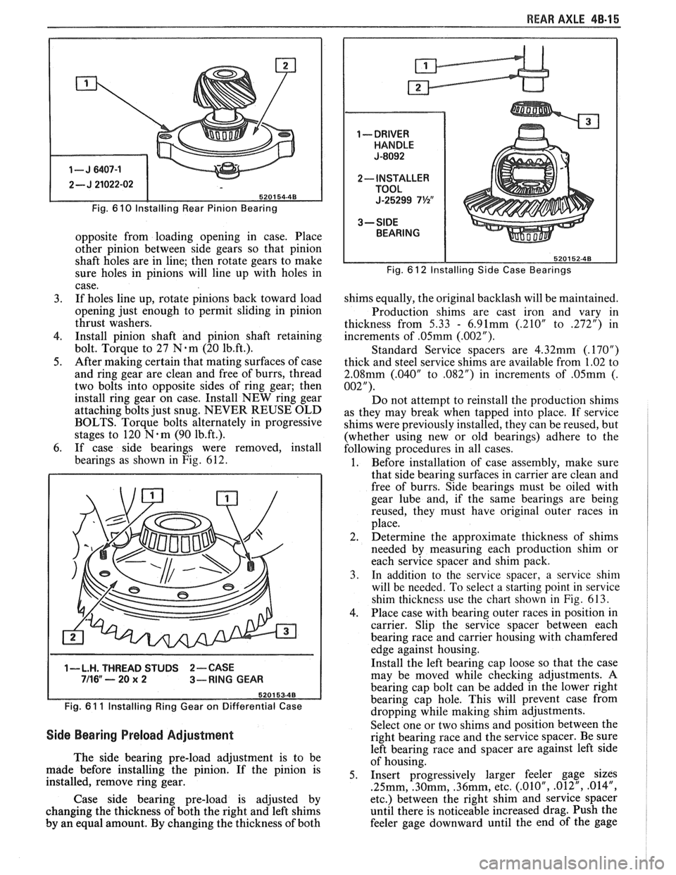
Fig. 6 10 lnstalling Rear Pinion Bearing
opposite from loading opening in case. Place
other pinion between side gears so that pinion
shaft holes are in line; then rotate gears to make
sure holes in pinions will line up with holes in
case.
3. If holes line up, rotate pinions back toward load
opening just enough to permit sliding in pinion
thrust washers.
4. Install pinion shaft and pinion shaft retaining
bolt. Torque to 27
N.m (20 1b.ft.).
5. After making certain that mating surfaces of case
and ring gear are clean and free of burrs, thread
two bolts into opposite sides of ring gear; then
install ring gear on case. Install NEW ring gear
attaching bolts just snug. NEVER REUSE OLD
BOLTS. Torque bolts alternately in progressive
stages to 120
N.m (90 1b.ft.).
6. If case side bearings were removed, install
bearings as shown in Fig. 612.
1-L.H. THREAD STUDS 2-CASE 711 6" ---- 20 x 2 3-RING GEAR
Fig.
6 1 1 lnstalling Ring Gear on Differential Case
Side Bearing Preload Adjustment
The side bearing pre-load adjustment is to be
made before installing the pinion. If the pinion is
installed, remove ring gear.
Case side bearing pre-load is adjusted by
changing the thickness of both the right and left shims
by an equal amount. By changing the thickness of both
Fig. 6 12 Installing Side Case Bearings
shims equally, the original backlash will be maintained.
Production shims are cast iron and vary in
thickness from
5.33 - 6.91mm (.210" to 272") in
increments of
.05mm (.002").
Standard Service spacers are 4.32mm (.17OU)
thick and steel service shims are available from 1.02 to
2.08mm (.040" to ,082") in increments of .05mm (.
002").
Do not attempt to reinstall the production shims
as they may break when tapped into place. If service
shims were previously installed, they can be reused, but
(whether using new or old bearings) adhere to the
following procedures in all cases.
1. Before installation of case assembly, make sure
that side bearing surfaces in carrier are clean and
free of burrs. Side bearings must be oiled with
gear lube and, if the same bearings are being
reused, they must have original outer races in
place.
2. Determine the approximate thickness of shims
needed by measuring each production shim or
each service spacer and shim pack.
3. In addition to the service spacer, a service shin1
will be needed. To select a starting point in service
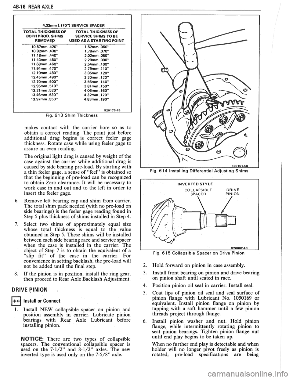
shim thickness use the chart shown in
Fig. 613.
4. Place case with bearing outer races in position in
carrier. Slip the service spacer between each
bearing race and carrier housing with chamfered
edge against housing.
Install the left bearing cap loose so that the case
may be moved while checking adjustments. A
bearing cap bolt can be added in the lower right
bearing cap hole. This will prevent case from
dropping while making shim adjustments.
Select one or two shims and position between the
right bearing race and the service spacer. Be sure
left bearing race and spacer are against left side
of housing.
5. Insert progressively larger feeler gage sizes
.25mm, .30mm, .36mm, etc. (.01OU, .012", .014",
etc.) between the right shim and service spacer
until there is noticeable increased drag. Push the
feeler gage downward until the end of
the gage
Page 289 of 1825
48-16 REAR AXLE
4.32mm (.170") SERVICE WACER
TOTAL THICKNESS OF TOTAL THICKNESS OF
BOTH PROD. SHIMS SERVICE SHIMS TO BE
REMOVED USED AS A STARTING POINT
Fig. 6 13 Shim Thickness
makes contact with the carrier bore so as to
obtain a correct reading. The point just before
additional drag begins is correct feeler gage
thickness. Rotate case while using feeler gage to
assure an even reading.
The original light drag is caused by weight of the
case against the carrier while additional drag is
caused by side bearing pre-load. By starting with
a thin feeler gage, a sense of "feel" is obtained so
that the beginning of pre-load can be recognized
to obtain Zero clearance. It will be necessary to
work case in and out and to the left in order to
insert the feeler gage.
6. Remove left bearing cap and shim from carrier.
The total shim pack needed (with no pre-load on
side bearings) is the feeler gage reading found in
Step
5 plus thickness of shims installed in Step 4.
7. Select two shims of approximately equal size
whose total thickness is equal to the value
obtained in Step
5. These shims will be installed
between each side bearing race and service spacer
when the case is installed in the carrier. The
object of Step 7 is to obtain the equivalent of a
"slip fit" of the case in the carrier. For
convenience in setting backlash, the pre-load will
not be added until the final step.
8. If the pinion is in position, install the ring gear,
then proceed to Rear Axle Backlash Adjustment.
DRIVE PINION
Install or Connect
1.
Install NEW collapsible spacer on pinion and
position assembly in carrier. Lubricate pinion
bearings with Rear Axle Lubricant before
installing pinion.
NOTICE: There are two types of collapsible
spacers. The conventional collapsible spacer is
used on the
7-1/2" and 8-1/2" axles. The new
inverted type is used only on the
7-5/8" axle.
Fig. 6 14 Installing Differential Adjusting Shims
COLLAPSIBLE DRIVE SPACER PINION I
Fig. 61 5 Collapsible Spacer on Drive Pinion
2.
Hold forward on pinion in case assembly.
3. Install front bearing on pinion and drive bearing
on pinion shaft until seated in race.
4. Position pinion oil seal in carrier. Install seal.
5. Coat lips of pinion oil seal and seal surface of
pinion flange with Lubricant No. 1050169 or
equivalent. Install pinion flange on pinion by
tapping with a soft hammer until a few pinion
threads project through flange.
6. Install pinion washer and nut. Hold pinion
flange, while intermittently rotating pinion to
seat pinion bearings. Tighten pinion flange nut
until end play begins to be taken up.
When no further end play is detectable and when
holder will no longer pivot freely as pinion is
rotated, pre-load specifications are being
Page 293 of 1825
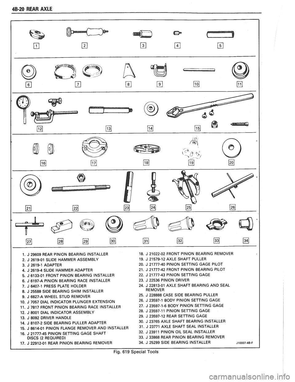
dB-20 RWR AXLE
1. J 29609 REAR PINION BEARING INSTALLER 18. J 21022-02
FRONT PINION BEARING REMOVER
2.
J 2619-01 SLIDE HAMMER ASSEMBLY 19. J 21579-12 AXLE
SHAFT PULLER
3.
J 2619-1 ADAPTER 20. J 21777-40 PINION
SETING GAGE PILOT
I 4.J2619-4SLlDEHAMMERADAPTER 21. J 21777-42 FRONT PINION BEARING PILOT
5. J 6133-01 FRONT PINION BEARING INSTALLER 22. J 21777-43
PINION SETTING GAGE
6. J 6197-A PINION BEARING RACE INSTALLER 23. J 22536
PINION DRIVER
7.
J 6407-1 PRESS PLATE HOLDER 24. J 22813-01 AXLE
SHAFT BEARING AND SEAL
8.
J 25588 SlDE BEARING SHIM INSTALLER REMOVER
9.
J 6627-A WHEEL STUD REMOVER 25. J 228888
CASE SlDE BEARING PULLER
10.
J 7057 DlAL INDICATOR PLUNGER EXTENSION 26. J 23597-1 BODY
PlNlON SETTING GAGE
11.
J 7817 FRONT PlNlON BEARING RACE INSTALLER 27. J 23597-1-6
BODY PlNlON SETING GAGE
12.
J 8001 DlAL INDICATOR ASSEMBLY 28. J 23597-11
PlNlON SETING GAGE
13.
J 8092 DRIVER HANDLE 29. J 23597-12
REAR SETTING GAGE
14.
J 8107-2 SlDE BEARING PULLER ADAPTER 30. J 23765 AXLE SHAFT BEARING
INSTALLER
15.
J 8614-01 PINION FLANGE REMOVER AND INSTALLER 31. 23771 AXLE SHAFT SEAL INSTALLER
16.
J 21777-45 PlNlON SETTING GAGE SHAFT 32. J 2391
1 PlNlON OIL SEAL INSTALLER
DISCS (2 REQUIRED) 33. J 33868
REAR PINION BEARING REMOVER
17.
J 22912-01 REAR PINION BEARING REMOVER 34. J 25299 SIDE BEARING
INSTALLER ~10007-40-F
Fig. 619 Special Tools
Page 296 of 1825
BRAKES 5-3
DIAGNOSIS AND INSPECTION
BRAKE SYSTEM TESTING
(Figures
2 through 4)
Brakes should be tested on dry, clean, reasonably
smooth and level roadway. A true test of brake performance
cannot be made if the roadway is wet, greasy or covered
with loose dirt so that all tires do not grip the road equally.
Testing will also be affected if the roadway is crowned
which would throw the weight of the car toward the wheels
on one side. If the roadway is too rough, the wheels will tend
to bounce. Test brakes at different car speeds with both light and
heavy pedal pressure, avoid locking the brakes and sliding
the tires. Locked brakes and sliding tires do not indicate
brake efficiency, because heavily braked, but turning
wheels will stop the car in less distance than locked brakes.
More tire-to-road friction is present with a heavily braked
turning tire than with a sliding tire. The brake system is designed and balanced to avoid
locking the wheels, except at very high deceleration levels.
The shortest stopping distance and best control is achieved
without brake lock-up.
Because of high deceleration capability, a firmer pedal
may be felt at higher deceleration levels.
External Conditions That Affect Brake Performance
1. Tires. Tires having unequal contact and grip on road
will cause unequal braking. Tires must be equally
inflated and tread pattern of right and left tires must
be approximately equal.
2. Car Loading. A heavily loaded car requires more
braking effort. When a car has unequal loading, the
most heavily loaded wheels require more braking
power than others.
3. Wheel Alignment. Misalignment of the wheels, par-
ticularly excessive camber and caster, will cause the
brakes to pull to one side.
4. Front Wheel Bearings. A loose front wheel bearing
BRAKE FLUID LEAKS
With engine running at idle and the transmission in neu-
tral, depress the brake pedal and hold a constant foot pres-
sure.
If the pedal gradually falls away with the constant
pressure, the hydraulic system may be leaking. Perform a
visual check to confirm any suspected leak.
Check the master cylinder fluid levels. While a slight drop
in reservoir level does result from normal lining wear, an
abnormally low level in either reservoir indicates
a leak in
the system. The hydraulic system may be leaking either
internally or externally. See "Master Cylinder Check."
Also, the system may appear to pass this test but still have
slight leakage.
If fluid levels are normal, check the vacuum booster
pushrod length. If an incorrect length pushrod is found,
adjust or replace the
pushrod. Check the service brake
pedal travel and the parking brake adjustment.
When checking the fluid levels, the master cylinder reser-
voir may be as low as
25 mm (1 inch) from the top if the front
linings are worn. This is not abnormal.
MASTER CYLINDER CHECK
These checks will help locate some master cylinder mal-
functions. Use the Brake Diagnosis Charts to help isolate
the problem if it is not found by using these tests.
1. Check for a cracked master cylinder casting or brake
fluid around the master cylinder. Leaks are indicated
only if there is at least a drop of fluid. A damp condi-
tion is not abnormal.
2. Check for a binding pedal linkage.
3. Disassemble the master cylinder and check for swol-
len or stretched piston
seal(s). If swollen seals are
found, substandard or contaminated brake fluid
should be suspected.
If contaminated, all compo-
nents should be disassembled and cleaned. All rub-
ber components should be replaced and all the pipes
should be flushed.
permits the front wheel to tilt and lose contact with the
SUBSTANDARD OR CONTAMINATED brake shoe linings causing erratic brake operation. BRAKE FLUID
WARNING LAMP OPERATION
The brake system uses a single red "BRAKE" warning
lamp located in the instrument panel cluster. When the
ignition switch is in the "START" position, the "BRAKE"
warning lamp should come on. It should go off when the
ignition switch returns to the "RUN" position.
The following conditions will activate the "BRAKE"
warning lamp:
1. Parking brake applied. The lamp should be on when
tfie parking brake is applied and the ignition switch is
"ON."
2. Pressure differential switch detects a failure. See
"Brake Pressure Differential Warning Switch" in this
section. Improper
brake fluid, mineral oil or water in the fluid may
cause the brake fluid to boil or the rubber components to
deteriorate.
If piston cups are swollen, the rubber parts have dete-
riorated. This deterioration may also be seen by swollen
wheel cylinder piston cups on the drum brake wheels or a
swollen master cylinder cover diaphragm.
If rubber deterioration is evident, disassemble all hydrau-
lic parts and wash with alcohol. Dry these parts with com-
pressed air before assembly to keep alcohol out of the
system. Replace all rubber parts in the system, including
hoses. Check for fluid on the linings. If excessive fluid is
found, replace the linings.
If master cylinder piston seals are satisfactory, check for
leakage or excessive heat conditions. If condition is not
found, drain fluid, flush with brake fluid, fill and bleed the
system.
Page 300 of 1825
BRAKES 5-7
ONmCAR SERVICE
BRAKE PEDAL REPLACEMENT
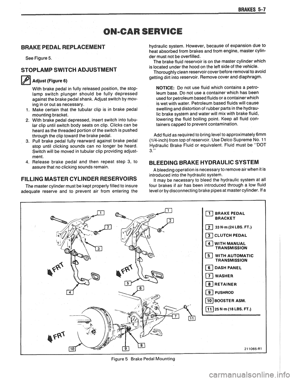
See Figure 5.
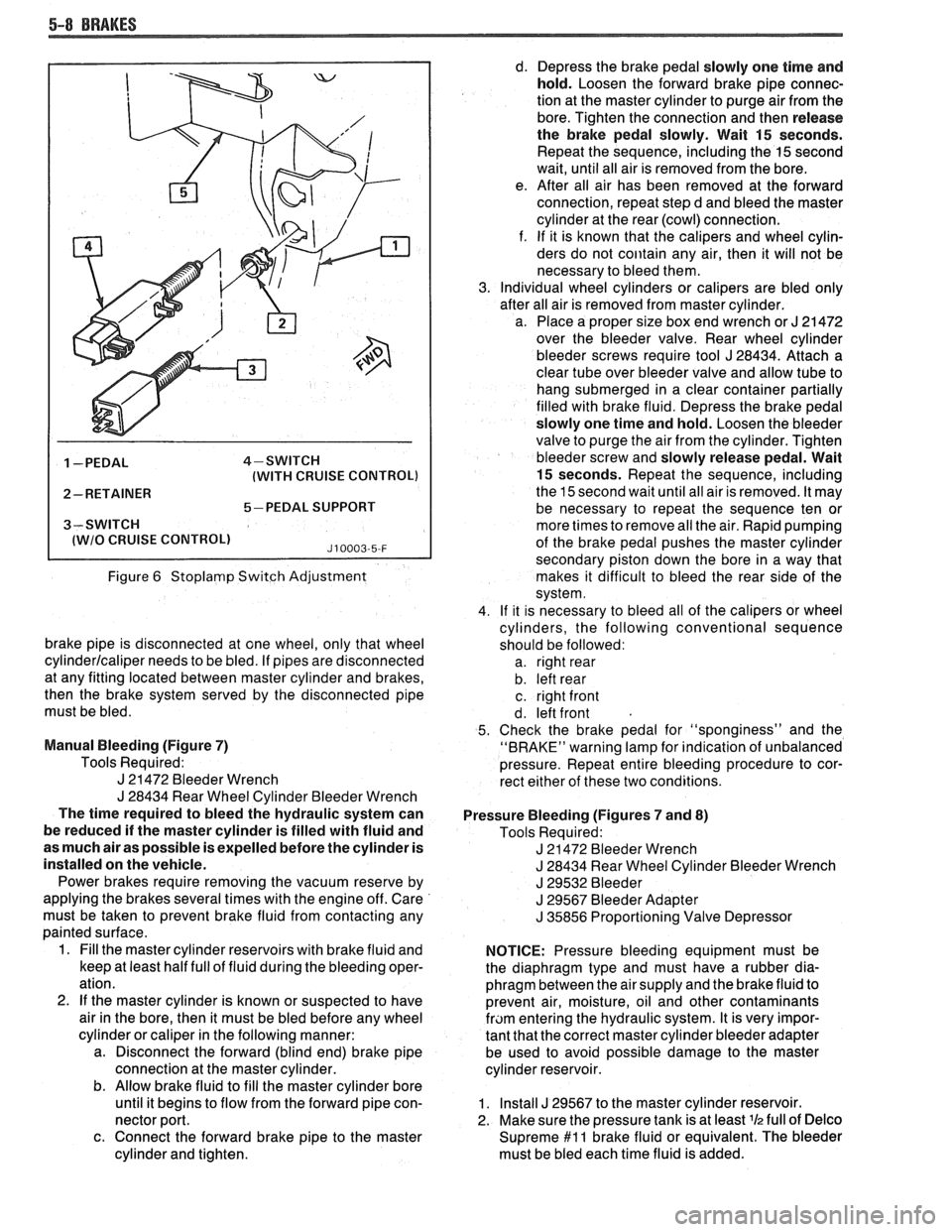
STOPLAMP SWITCH ADJUSTMENT
Adjust (Figure 6)
With brake pedal in fully released position, the stop-
lamp switch plunger should be fully depressed
against the brake pedal shank. Adjust switch by mov-
ing in or out as necessary.
1. Make certain that the tubular clip is in brake pedal
mounting bracket.
2. With brake pedal depressed, insert switch into tubu-
lar clip until switch body seats on clip. Clicks can be
heard as the threaded portion of the switch is pushed
through the clip toward the brake pedal.
3. Pull brake pedal fully rearward against brake pedal
stop until clicking sounds can no longer be heard.
Switch will be moved in tubular clip providing adjust-
ment.
4. Release brake pedal and then repeat step 3, to
assure that no clicking sounds remain.
FILLING MASTER CYLINDER RESERVOIRS
The master cylinder must be kept properly filled to insure
adequate reserve and to prevent air from entering the hydraulic
system. However, because of expansion due to
heat absorbed from brakes and from engine, master cylin-
der must not be overfilled.
The brake fluid reservoir is on the master cylinder which
is located under the hood on the left side of the vehicle.
Thoroughly clean reservoir cover before removal to avoid
getting dirt into reservoir. Remove cover and diaphragm.
NOTICE: Do not use fluid which contains a petro-
leum base. Do not use a container which has been
used for petroleum based fluids or a container which
is wet with water. Petroleum based fluids will cause
swelling and distortion of rubber parts in the hydrau-
lic brake system and water will mix with brake fluid,
lowering the fluid boiling point. Keep all fluid con-
tainers capped to prevent contamination.
Add fluid as required to bring level to
approximately6mm
(114-inch) from top of reservoir. Use Delco Supreme No. 1 1
Hydraulic Brake Fluid or equivalent. Fluid must be "DOT
3."
BLEEDING BRAKE HYDRAULIC SYSTEM
A bleeding operation is necessary to remove air when it is
introduced into the hydraulic system. It may be necessary to bleed the hydraulic system at all
four brakes if air has been introduced through a low fluid
level or by disconnecting brake pipes at master cylinder. If a
Figure
5 Brake Pedal Mounting
Page 301 of 1825
5-8 BRAKES
1 -PEDAL 4-SWITCH
(WITH CRUISE CONTROL)
2- RETAINER
5-PEDAL SUPPORT
3-SWITCH
I lWlO CRUISE CONTROLl J10003-5-F
Figure 6 Stoplamp Switch Adjustment
brake pipe is disconnected at one wheel, only that wheel
cylinderlcaliper needs to be bled. If pipes are disconnected
at any fitting located between master cylinder and brakes,
then the brake system served by the disconnected pipe
must be bled.
Manual Bleeding (Figure
7)
Tools Required:
J 21472 Bleeder Wrench
J 28434 Rear Wheel Cylinder Bleeder Wrench
The time required to bleed the hydraulic system can
be reduced if the master cylinder is filled with fluid and
as much air as possible is expelled before the cylinder is
installed on the vehicle.
Power brakes require removing the vacuum reserve by
applying the brakes several times with the engine off. Care
must be taken to prevent brake fluid from contacting any
painted surface.
1. Fill the master cylinder reservoirs with brake fluid and
keep at least half full of fluid during the bleeding oper-
ation.
2.
If the master cylinder is known or suspected to have
air in the bore, then it must be bled before any wheel
cylinder or caliper in the following manner:
a. Disconnect the forward (blind end) brake pipe
connection at the master cylinder.
b. Allow brake fluid to fill the master cylinder bore
until it begins to flow from the forward pipe con-
nector port.
c. Connect the forward brake pipe to the master
cylinder and tighten. d.
Depress the brake pedal slowly one time and
hold. Loosen the forward brake pipe connec-
tion at the master cylinder to purge air from the
bore. Tighten the connection and then release
the brake pedal slowly. Wait
15 seconds.
Repeat the sequence, including the
15 second
wait, until all air is removed from the bore.
e. After all air has been removed at the forward
connection, repeat step d and bleed the master
cylinder at the rear (cowl) connection.
f. If it is known that the calipers and wheel cylin-
ders do not
coiitain any air, then it will not be
necessary to bleed them.
Individual wheel cylinders or calipers are bled only
after all air is removed from master cylinder.
a. Place a proper size box end wrench or
J 21 472
over the bleeder valve. Rear wheel cylinder
bleeder screws require tool
J 28434. Attach a
clear tube over bleeder valve and allow tube to
hang submerged in a clear container partially
filled with brake fluid. Depress the brake pedal
slowly one time and hold. Loosen the bleeder
valve to purge the air from the cylinder. Tighten
bleeder screw and slowly release pedal. Wait
15 seconds. Repeat the sequence, including
the 15 second wait until all air is removed. It may
be necessary to repeat the sequence ten or
more times to remove all the air. Rapid pumping
of the brake pedal pushes the master cylinder
secondary piston down the bore in a way that
makes it difficult to bleed the rear side of the
system.
If it is necessary to bleed all of the calipers or wheel
cylinders, the following conventional sequence
should be followed: a. right rear
b. left rear
c. right front
d. left front
Check the brake pedal for "sponginess" and the
"BRAKE" warning lamp for indication of unbalanced
pressure. Repeat entire bleeding procedure to cor-
rect either of these two conditions.
Pressure Bleeding (Figures
7 and 8)
Tools Required:
J 21472 Bleeder Wrench
J 28434 Rear Wheel Cylinder Bleeder Wrench
J 29532 Bleeder
J 29567 Bleeder Adapter
J 35856 Proportioning Valve Depressor
NOTICE: Pressure bleeding equipment must be
the diaphragm type and must have a rubber dia-
phragm between the air supply and the brake fluid to
prevent air, moisture, oil and other contaminants
fram entering the hydraulic system. It is very impor-
tant that the correct master cylinder bleeder adapter
be used to avoid possible damage to the master
cylinder reservoir.
1. Install J 29567 to the master cylinder reservoir.
2. Make sure the pressure tank is at least
lh full of Delco
Supreme $1 1 brake fluid or equivalent. The bleeder
must be bled each time fluid is added.