Page 507 of 1825

CHART A-3
(Page 2 of 2 )
ENGINE CRANKS BUT WILL NOT RUN
5.OL (VIN E) "F'XSERIES (TBI)
Circuit Description:
This chart assumes that battery condition and engine cranking speed are OK, and there is adequate fuel in
the tank.
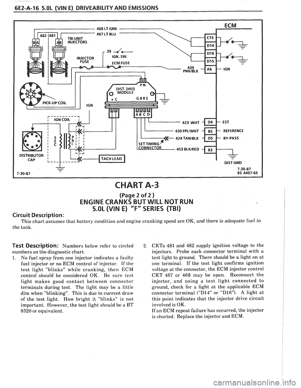
Test Description: Numbers below refer to circled 2.
numbers on the diagnostic chart.
1. No fuel spray from one injector indicates a faulty
fuel injector or no ECM control of injector. If the
test light "blinks" while cranking, then
ECM
control should be considered OK. Be sure test
light makes good contact between connector
terminals during test.
The light may be a little
dim when "blinking". This is due to current draw
of the test light. How bright it "blinks" is not
important. However, the test light should be
a BT
8320 or equivalent.
CKTs 481 and 482 supply ignition voltage to the
injectors. Probe each connector terminal with a
test light to ground. There should be a light on at
one terminal.
If the test light confirms ignition
voltage at the connector, the ECM injector control
CKT 467 or 468 may be open. Reconnect the
injector, and using a test light connected to
ground, check for a light at the applicable ECM
connector terminal
("D14" or "D16"). A light at
this point indicates that the injector drive circuit
involved is OK.
If an ECM repeat failure has occurred, the injector
is shorted. Replace the injector and ECM.
Page 512 of 1825
DRIVEABILITY AND EMISSIONS 5.OL (VIN E) CEZ-A-21
@ DISCONNECT FUEL RETURN LlNE
FLEXIBLE HOSE.
ATTACH
5/16 1.D. FLEX HOSE TO
THROTTLE BODY SIDE OF RETURN LINE.
INSERT THE OTHER END IN AN APPROVED
GASOLINE CONTAINER.
r NOTE FUEL PRESSURE WITHIN 2 SECONDS
@ APPLY 12 VOLTS TO FUEL
CHECK FOR RESTRICTED
FUEL RETURN
LlNE FROM
THROTTLE BODY.
CLEAR CODES AND CONFIRM "CLOSED LOOP
" OPERATION AND NO "SERVICE ENGINE SOON" LIGHT.
Page 518 of 1825
DRIVEABILITY AND EMISSIONS S.OL (VIN E) 6E2-A-27
" SHOULD DISPLAY 130°C OR MORE.
DIAGNOSTIC AID
CLEAR CODES AND CONFIRM "CLOSED LOOP" OPERATION AND NO "SERVICE ENGINE SOON" LIGHT.
COOLANT
SENSOR
TEMPERATURE TO RESISTANCE VALUES
(APPROXIMATE)
"F "C OHMS
210 100 185
160 70 450
100 38 1,800
70 20 3,400
40
4 7,500
20 -7 13,500
0
-1 8 25,000
-40 -40 100,700
Page 519 of 1825

6EZ-A-28 5.OL (VIN E) DRIVEABILITY AND EMISSIONS
FRONT VIEW OF CONNECTOR
5V REFERENCE
TO
MAP SENSOR
CODE 21
THROTLE POSITION SENSOR (TPS) CIRCUIT
(SIGNAL VOLTAGE HIGH)
5.OL (VIN E) "F" "SERIES ("FBI)
Circuit Description:
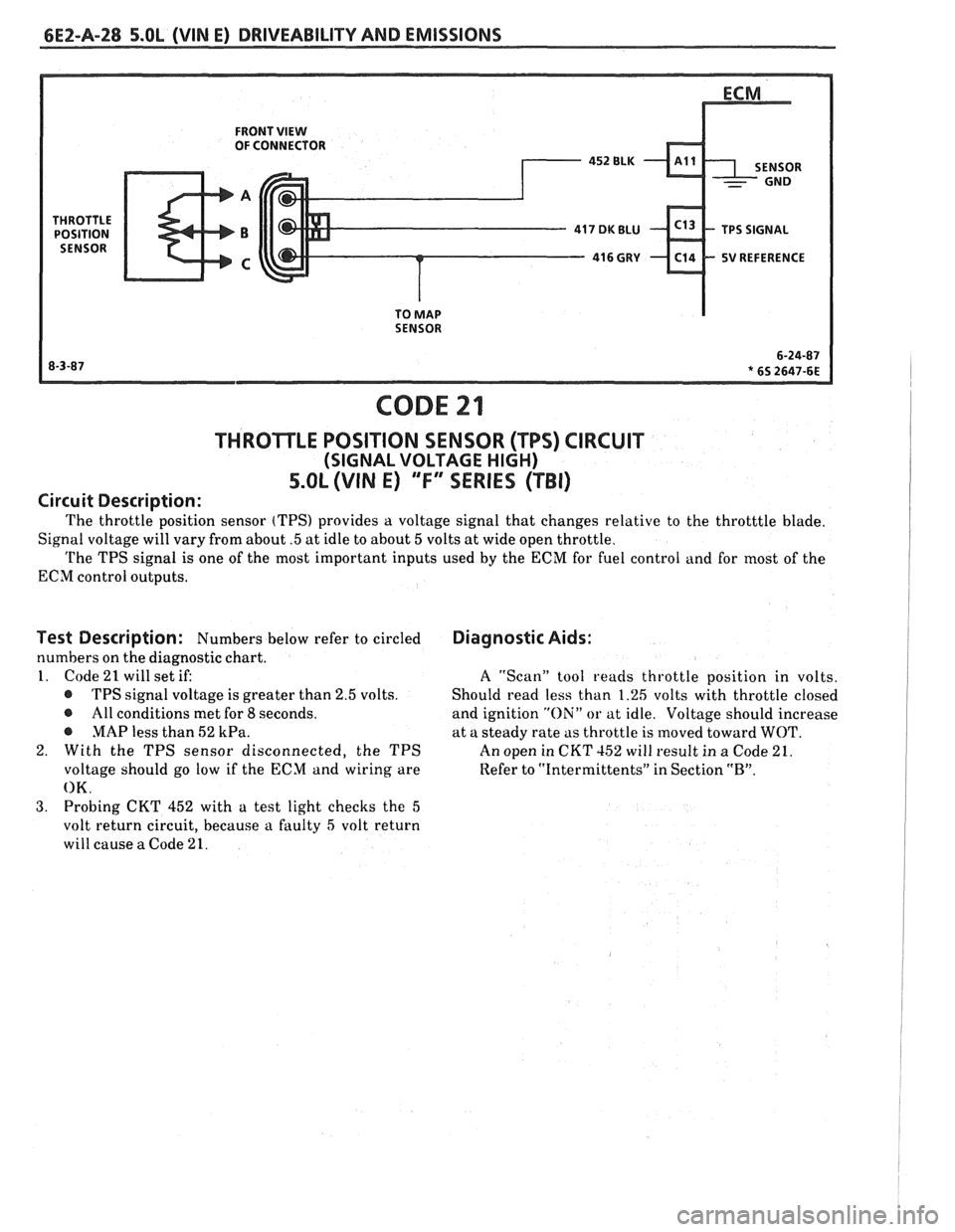
The throttle position sensor (TPS) provides a voltage signal that changes relative to the throtttle blade.
Signal voltage will vary from about
.5 at idle to about 5 volts at wide open throttle.
The TPS signal is one of the most important inputs used by the ECM for fuel control and for most of the
ECM control outputs.
Test Description: Numbers below refer to circled
numbers on the diagnostic chart.
1. Code
21 will set if:
@ TPS signal voltage is greater than 2.5 volts.
@ All conditions met for 8 seconds.
@ MAP less than 52 kPa.
2. With the TPS sensor disconnected, the TPS
voltage should go low if the ECM and wiring are
OK.
3. Probing CKT 452 with a test light checks the 5
volt return circuit, because a faulty 5 volt return
will cause
a Code 21.
Diagnostic Aids:
A ''Scan" tool reads throttle position in volts.
Should read less than 1.26 volts with throttle closed
and ignition
"Oili" or at idle. Voltage should increase
at a steady rate as throttle is moved toward
WOT.
An open in CKT 152 will result in a Code 21.
Refer to
"Intermittents" in Section "B".
Page 526 of 1825
DRIVEABILITY AND EMISSIONS 5.OL (WIN E) 6E2-A-35
NOTE: TO PREVENT MISDIAGNOSIS, THE TECHNICIAN SHOULD REVIEW ELECTRICAL SECTION "8A"
OR THE ELECTRICAL TROUBLESHOOTING MANUAL AND IDENTIFY THE TYPE OF VEHICLE
SPEED SENSOR USED PRIOR TO USING THIS CHART. DISREGARD CODE
24 IF SET WHEN
DRIVE WHEELS ARE NOT TURNING.
CTOR TERMINAL "K"
e IGNITION "ON." @ BACK PROBE 15-WAY I.P. CONNECTOR
ISPLAY 10 VOLTS OR MORE.
ONNECTOR AND
VSS BUFFER
CLEAR CODES AND CONFIRM "CLOSED LOOP
" OPERATION AND NO "SERVICE ENGINE SOON" LIGHT.
Page 530 of 1825
DRIVEABILITY AND EMISSIONS 5.OL (VIN E) 6EZ-A-39
BEFORE USING THIS CHART, CHECK FOR MANIFOLD VACUUM TO EGR
@ GROUND DIAGNOSTIC TERMINAL. @ INSTALL A HAND HELD VACUUM PUMP WITH GAGE TO MANIFOLD
PUMP TO EGR VALVE.
@ USING A MIRROR,
OBSERVE EGR
DIAPHRAGM WHILE
APPLYING VACUUM.
DIAPHRAGM SHOULD OR
TERMINALS.
MOVE FREELY AND "ON",
ENGINE "OFF".
HOLD VACUUM FOR AT T
SHOULD LIGHT.
LEAST
20 SECONDS.
OBSERVE VACUUM GAGE ON
VACUUM PUMP.
HAS MOVED TO SEATED POSITION
CLEAR CODES AND CONFIRM "CLOSED LOOP"
OP
Page 535 of 1825

6E2-A-44 5.OL (WIN E) DRIVEABILITY AND EMISSIONS
DISTRIBUTOR 4 TERM
CONNECTOR
DISTRIBUTOR
430 PPVWHT
424 TANIBLK
CODE 42
ELECTRONlC SPARK TIMING (EST) CIRCUIT
5.OL (VIN E) ""FYSERIES (TBI)
Circuit Description:
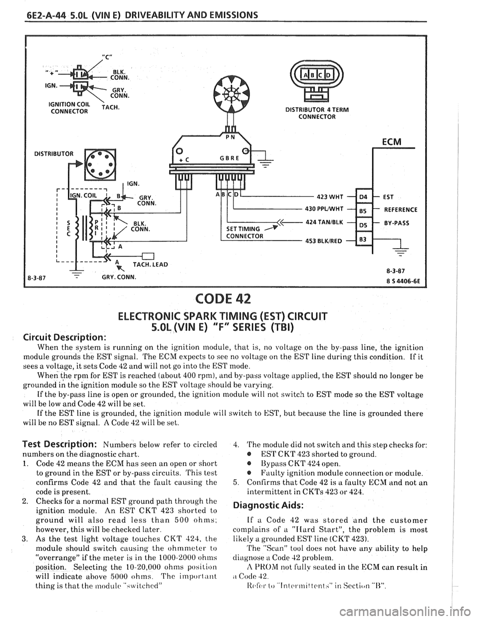
When the system is running on the ignition module, that is, no voltage on the by-pass line, the ignition
module grounds the EST signal. The ECM expects to see no voltage on the EST line during this condition. If it
sees a voltage, it sets Code 42 and will not go into the EST mode.
When the
rpm for EST is reached (about 400 rpm), and by-pass voltage applied, the EST should no longer be
grounded
i; the ignition module so the EST voltage should be varying.
If the by-pass line is open or grounded, the ignition module will not
switcli to EST mode so the EST voltage
will be low and Code 42 will be set.
If the EST line is grounded, the ignition module
will switch to EST, but because the line is grounded there
will be no EST signal.
A Code 42 will be set.
Test Description: Numbers below refer to circled
numbers on the diagnostic chart.
1. Code 42 means the ECM has seen an open or short
to ground in the EST or by-pass circuits. This test
confirms Code 42 and that the fault causing the
code is present.
2. Checks for a normal EST ground path through the
ignition module.
An EST CKT 423 shorted to
ground will also read less than 500 ohms.
however, this will be checked later.
3. As the test light voltage touches CKT 424, the
module should switch causing the ohmmeter
to
"overrange" if the meter is in the 1000-2000 ohnls
position. Selecting the 10-20,000 ohms position
will indicate
above 5000 ohms. The important
thing is that the moclul(~ ".;~vitched"
4. The module did not switch and this step checks for:
@ ES'I' CKT 423 shorted to ground.
@ By pass C KT 424 open.
@ Faulty ignition module connection or module.
5. Confirms that Code 42 is a faulty ECM and not an
intermittent in
CKTs 423 or 424.
Diagnostic Aids:
If a Code 42 was stored and the customer
complains of
a "IIard Start", the problem is most
likely a grounded EST line (CKT 423).
'I'he "Scan" tool does not have any ability to help
diagnose
a Code 42 problem.
rl PROM not Sully seated in the ECM can result in
Code 42
11~1'(.1- 10 '.In1 c.l.lnlt tc~nth" in Sectiotl "13".
Page 537 of 1825

CODE 43
ELECTRONIC SPARK CONTROL (ESC) CIRCUIT
5.0L (VIN E) "F" SERIES (TBI)
Circuit Description:
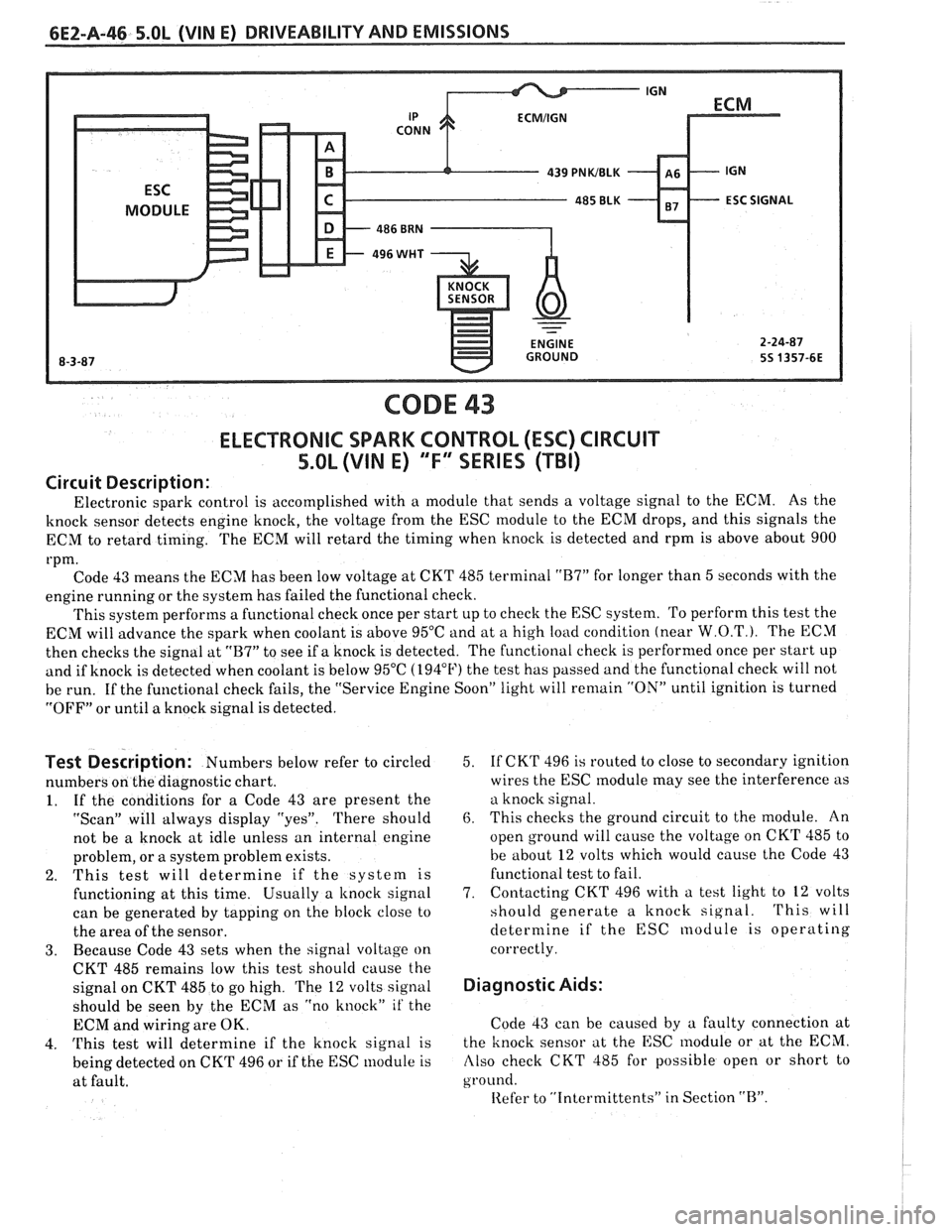
Electronic spark control is accomplished with a module that sends a voltage signal to the ECM. As the
knock sensor detects engine knock, the voltage from the ESC module to the ECM drops, and this signals the
ECM to retard timing. The ECM will retard the timing when knock is detected and rpm is above about 900
rpm. Code 43 means the ECM has been low voltage at CKT 485 terminal
"B7" for longer than 5 seconds with the
engine running or the system has failed the functional check.
This system performs a functional check once per start up to check the ESC system. To perform this test the
ECM will advance the spark when coolant is above 95°C and at
a high load condition (near W.O.T.). The ECM
then checks the signal at
"B7" to see if a knock is detected. The functional check is performed once per start up
and if knock is detected when coolant is below 95°C (194°F) the test has passed and the functional check will not
be run. If the functional check fails, the "Service Engine Soon" light will
remain "ON" until ignition is turned
"OFF" or until a knock signal is detected.
Test Description: Numbers below refer to circled
numbers on the diagnostic chart.
1. If the conditions for a Code 43 are present the
"Scan" will always display "yes". There should
not be a knock at idle unless an internal engine
problem, or a system problem exists.
2. This test will determine if the system is
functioning at this time. Usually a
knock signal
can be generated by tapping on the block close to
the area of the sensor.
3. Because Code 43 sets when the signal voltage on
CKT 485 remains low this test should cause the
signal on CKT 485 to go high. The
12 volts signal
should be seen by the ECM as "no knock"
it' the
ECM and wiring are OK.
4.
This test will determine if the knock signal is
being detected on CKT 496 or if the ESC module is
at fault. 5.
If
CKT 496 is routed to close to secondary ignition
wires the ESC
module may see the interference as
a knock signal.
6. This checks the ground circuit to the module. An
open ground will cause the voltage on CKT 485 to
be about
12 volts which would cause the Code 43
functional test to fail.
7. Contacting
CKT 496 with a test light to
12 volts
should generate a knock signal.
This will
determine if the ESC nodule is operating
correctly.
Diagnostic Aids:
Code 43 can be caused by a faulty connection at
the knock sensor at the ESC
lnodule or at the ECM.
Also check CKT 485 for possible open or short to
ground.
Iiefer to "Intcrmittents" in Section "B".