1988 PONTIAC FIERO light
[x] Cancel search: lightPage 563 of 1825
6E2-C1-8 5.OL (VIM E) DRIVEABILITY AND EMISSIONS
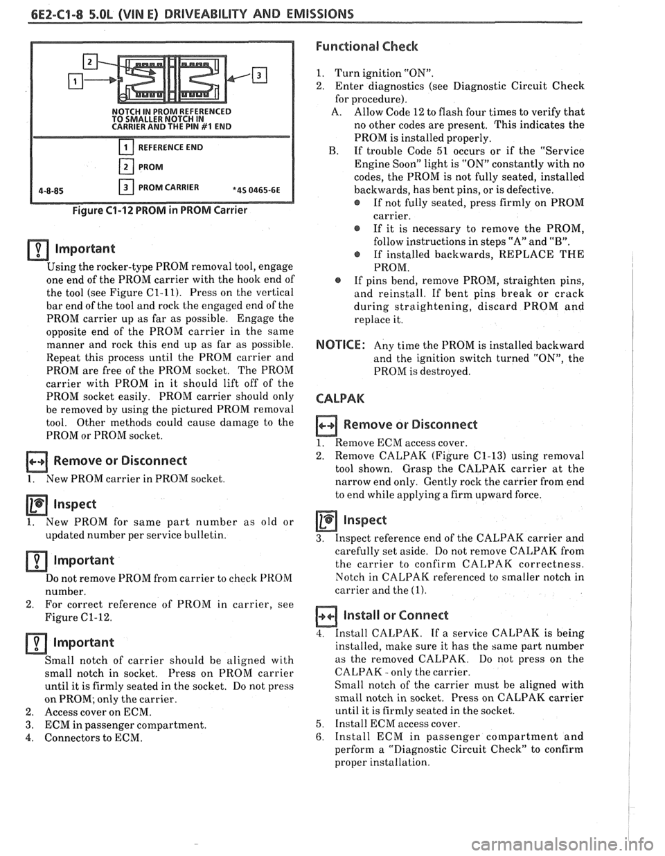
NOTCH IN PROM REFERENCED
TO SMALLER NOTCH IN
CARRIER AND THE PIN
#I END
REFERENCE END
PROM
PROM CARRIER *4S 0465-6E
Figure 61-12 PROM in PROM Carrier
lmportant
Using the rocker-type PROM removal tool, engage
one end of the PROM carrier with the hook end of
the tool (see Figure
C1-11). Press on the vertical
bar end of the tool and rock the engaged end of the
PROM carrier up as far as possible. Engage the
opposite end of the PROM carrier in the same
manner and rock this end up as far as possible.
Repeat this process until the PROM carrier and
PROM are free of the PROM socket. The PROM
carrier with PROM in it should lift off of the
PROM socket easily. PROM carrier should only
be removed by using the pictured PROM removal
tool. Other methods could cause damage to the
PROM or PROM socket.
Remove or Disconnect
1. New PROM carrier in PROM socket
Inspect
1. New
PROM for same part number as old or
updated number per service bulletin.
Important
Do not remove PROM from carrier to check PROM
number.
2. For correct
reference of PROM in carrier, see
Figure
C1-12.
important
Small notch of carrier should be aligned with
small notch in socket. Press on
PROM carrier
until it is firmly seated in the socket. Do not press
on PROM; only the carrier.
2. Access cover on ECM.
3. ECM in passenger compartment.
4. Connectors to ECM.
Functional Check
1. Turn ignition "ON".
2. Enter diagnostics (see Diagnostic Circuit Check
for procedure).
A. Allow Code 12 to flash four times to verify that
no other codes are present. This indicates the
PROM is installed properly.
B. If trouble Code 51 occurs or if the "Service
Engine Soon" light is "ON" constantly with no
codes, the PROM is not fully seated, installed
backwards, has bent pins, or is defective.
@ If not fully seated, press firmly on PROM
carrier.
If it is necessary to remove the PROM,
follow instructions in steps "A" and
"B".
@ If installed backwards, REPLACE THE
PROM.
@ If pins bend, remove PROM, straighten pins,
and reinstall. If bent pins break or crack
during straightening, discard PROM and
replace it.
NOTICE: Any time the PROM is installed backward
and the ignition switch turned "ON", the
PROM is destroyed.
CALPAK
n Remove or Disconnect
1. Remove ECM access cover.
2. Remove
CALPAK (Figure
C1-13) using removal
tool shown. Grasp the CALPAK carrier at the
narrow end only. Gently rock the carrier from end
to end while applying a firm upward force.
Inspect
3. Inspect reference end of the CALPAK carrier and
carefully set aside. Do not remove CALPAK from
the carrier to confirm CALPAK correctness.
Notch in CALPAK referenced to smaller notch in
carrier and the
(1).
a Install or Connect
4. Install CALPAK. If a service CALPAK is being
installed, make sure it has the same part number
as the removed CALPAK. Do
not press on the
CALPAK
- only the carrier.
Small notch of the carrier must be aligned with
small notch in socket. Press on CALPAK carrier
until it is firmly seated in the socket.
5. Install ECM access cover.
6. Install ECM in passenger compartment and
perform a "Diagnostic Circuit Check" to confirm
proper installation.
Page 569 of 1825

6E2-C1-14 DRlVEABlLlTV AND EMISSIONS - 5.OL (VIN E)
806 PPUWHT CRANK SIGNAL
STARTER SOLENOID
('HOT' DURING CRANK)
CHART C-l B
CRANK SIGNAL
5.OL (VIN E) "F" "SERIES (TBI)
Circuit Description:
Crank signal is a 12 volts signal to the ECM during cranking to allow enrichment and cancel diagnostics
until engine is running and 12 volts is no longer on circuit.
Test Description: Numbers below refer to circled 2. Checks to determine if source of blown fuse was a
numbers on the diagnostic chart. faulty
ECM.
1. Checks for normal (cranking) voltage to terminal
"C9" of ECM. Test light should be "ON" during
cranking.
Page 570 of 1825

DRIVEABILITY AND EMISSIONS - 5.0b (VIN E) 6E2-C9-15
RECHECK FUSE.
CLEAR CODES AND CONFIRM "CLOSED LOOP" OPERATION AND NO "SERVICE
ENGINE SOON" LIGHT.
Page 591 of 1825
6E2-CZ-16 DRIVEABILITY AND EMISSIONS - 5.OL (WIN E)
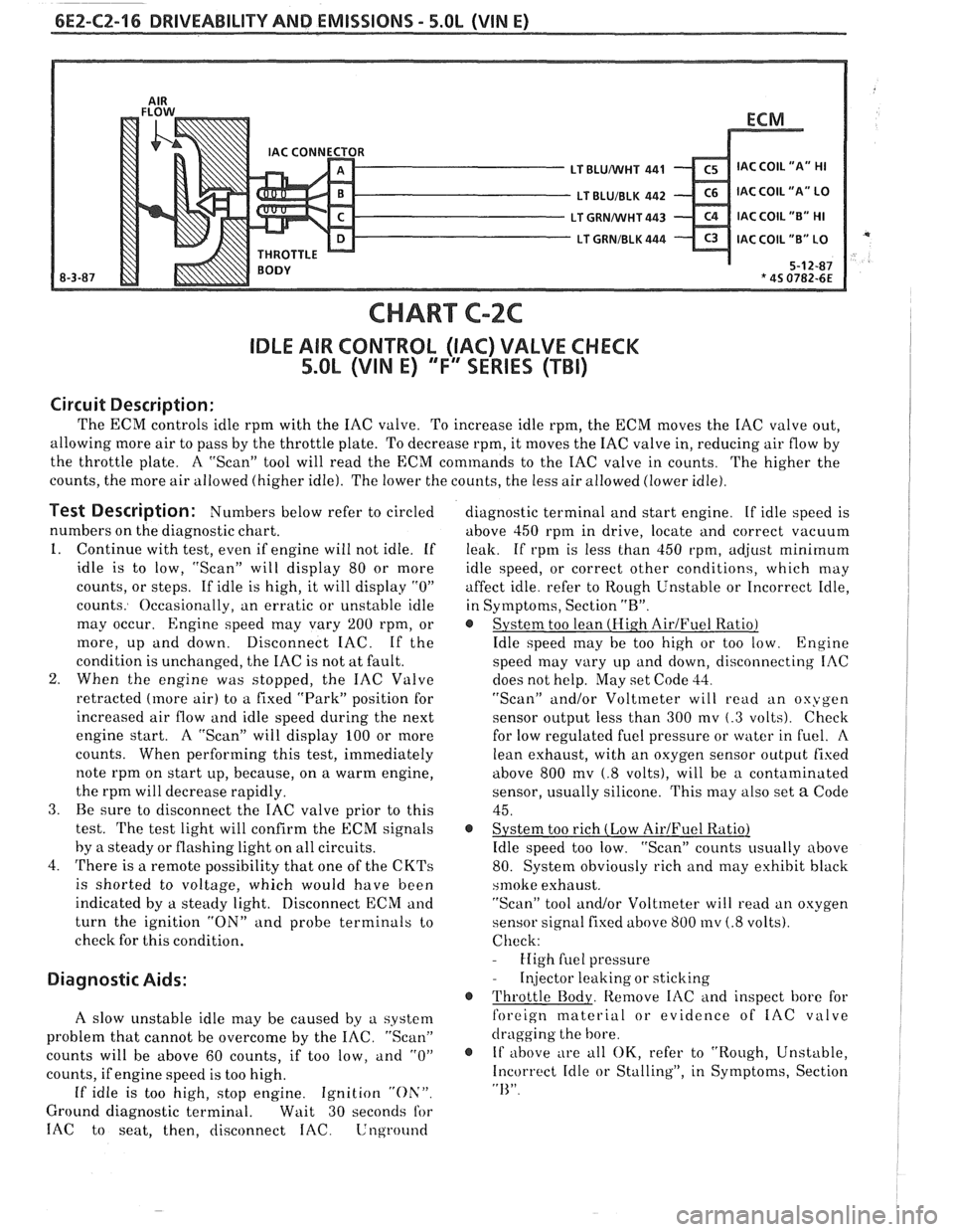
CHART C-2C
IDLE AIR CONTROL (IAC) VALVE CHECK
5.OL (VIN E) "F'" SERIES (TBI)
Circuit Description:
The ECM controls idle rprn with the IAC valve. To increase idle rpm, the ECM moves the IAC valve out,
allowing more air to pass by the throttle plate. To decrease rpm, it moves the IAC valve in, reducing air flow by
the throttle plate. A "Scan" tool will read the
ECM commands to the IAC valve in counts.
The higher the
counts, the more air allowed (higher idle). The lower the counts, the less air allowed (lower idle).
Test Description: Numbers below refer to circled
numbers on the diagnostic chart.
1. Continue with test, even if engine will not idle. If
idle is to low, "Scan" will display 80 or more
counts, or steps. If idle is high, it will display
"0"
counts. Occasionally, an erratic or unstable idle
may occur.
Engine speed may vary 200 rpm, or
more, up and down. Disconnect IAC. If the
condition is unchanged, the IAC is not at fault.
2. When the engine was stopped, the IAC Valve
retracted (more air) to a fixed "Park" position for
increased air flow and idle speed during the next
engine start. A "Scan" will display 100 or more
counts. When performing this test, immediately
note rprn on start up, because, on a warm engine,
the rprn will decrease rapidly.
3. Be sure to disconnect the IAC valve prior to this
test.
The test light will confirm the ECM signals
by
a steady or flashing light on all circuits.
4. There is a remote possibility that one of the
CKTs
is shorted to voltage, which would have been
indicated by a steady light. Disconnect ECM and
turn the ignition
"ON" and probe terminals to
check for this condition.
Diagnostic Aids:
A slow unstable idle may be caused by a system
problem that cannot be overcome by the
IAC. "Scan"
counts will be above 60 counts, if too low,
and "0"
counts, if engine speed is too high.
If idle is too high, stop engine. Ignition "Oh'".
Ground diagnostic terminal. Wait 30 seconds for
IAC to seat, then, disconnect IAC. Lnground
diagnostic terminal and start engine. If idle speed is
above 450 rprn in drive, locate and correct vacuum
leak. If rpm is less than 450 rpm,
ad,jrlst minimum
idle speed, or correct other conditions, which may
affect idle. refer to Rough Unstable or Incorrect Idle,
in Symptoms, Section
"R".
@ System too lean (Hi.gh AirJFuel Ratio)
Idle speed may be too high or too low. Engine
speed may vary up and down, disconnecting IAC
does not help. May set Code
33.
"Scan" and/or Voltmeter will read an oxygen
sensor output less than 300 mv
(.3 volts). Check
for low regulated fuel pressure or water in
fuel. A
lean exhaust, with an oxygen sensor outpirt fixed
above 800
mv (.8 volts), will be a contaminated
sensor, usually silicone. This may also set
a Code
45.
@ System too rich (Low AirIFuel Ratio)
Idle speed too low. "Scan" counts usually above
80. System obviously rich and may exhibit black
srnoke exhaust.
"Scan" tool and/or Voltmeter will
read an oxygen
sensor signal fixed above 800
mv (.8 volts).
Check:
- High fuel pressure
- Injector leaking or sticking
@ Throttle Body. Remove IAC and inspect bore for
foreign material or evidence of
IAC valve
dragging the bore.
@ If above ;
e all OK, refer to "Rough, Unstable,
Incorrect Idle or Stalling", in Symptoms, Section
"I<".
Page 598 of 1825
DRIVEABILITY AND EMISSIBNO 5.OL (VIN E) 6E2-C3-5
r GROUND DIAGNOSTIC TERMINAL.
e DISCONNECT VACUUM HOSES FROM PURGE SOLENOID.
NESS CONNECTOR
TERMINAL WITH A
TEST LIGHT TO
REPAIR SHORT
TO VOLTAGE
IN
Page 603 of 1825
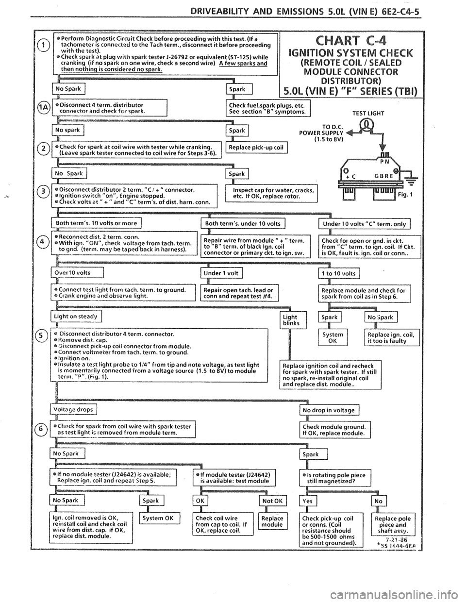
6E2-C4-4 5.OL (VIN E) DRIVEABILITY AND EMISSIONS
CONNECTOR
430 PPUWHf
424 TANIBLK
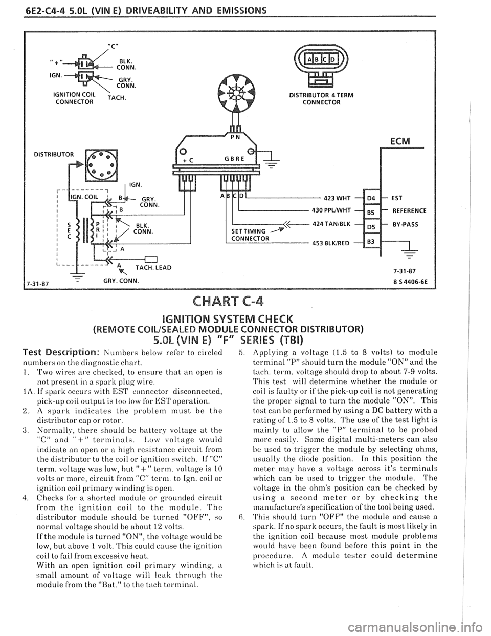
CHART C-4
IGMB"$IIQN SYSTEM CHECK
(REMOTE COILSEALED MODULE CONNECTOR DISTRIBUTOR)
5.OL (VIN E) 'TF"7SEWBES (TBi)
Test De~driptian: Siin~bers below refer to circled
numbers
on the diagilostic chart.
1. 'Two wires are checkecl, to ensure that ti11 open is
not present
in a spark plug wire.
IA. If spark occurs with EST connector disconnected,
pick-LIP coil
oiltp~it is too !OW for l,:SrI' operation.
2. A spark indicates t,he problem must be the
distributor cap or rotor.
3. Normally, there should be battery voltage at the "c" ailti " -I-" terminals. Low voltage would
indicate an open or
a high resistance circuit from
the distributor to the coil or ignition switch. If "C"
term. voltage was low, but
"+" term. voltage is 10
volts or more, circuit
from "C" term. to Ign. coil or
ignition coil
primary winding is open.
4. Checks for a shorted module or grounded circuit
from the ignition coil to the module.
'I'hc
distributor module should be turned "OFF", so
normal voltage should be
about 12 volts.
If the module is turned "ON", the voltage would be
low, but above
1 volt. This could cause the ignition
coil to fail from excessive heat.
With an open ignition coil primary winding,
a
small amount of voltage will leak throtrgh the
module from the "Bat." to the tach terminal.
5. Applying a voltage (1.5 to 8 volts) to module
terminal
"P" should turn the module "ON" and the
tach. term. voltage should drop to about 7-9 volts.
'I'his test will determine whether the module or
coil is faulty or if the pick-up coil is not generating
the proper signal to turn the module "ON". This
test can be performed by using a DC battery with a
rating of 1.5 to
8 volts. The use of the test light is
~nainly to tillow the "P" terminal to be probed
tilore easily. Some digital multi-meters can also
be used to trigger the
module by selecting ohms,
i~sually the diode position. 111 this position the
meter may have a voltage across it's terminals
which can be
used to trigger the module. The
voltage in the ohm's position can be checked
by
using a second meter or by checking the
manufacture's specification of the tool being used.
6. 'I'his should turn "OFF" the module and cause a
spark. If no spark occurs, the fault is most likely in
the ignition coil because
most module problems
would have been found before this point in the
procedure.
A modulc tester could determine
which is at fault.
Page 604 of 1825
DRIVEABILITY AND EMISSIONS 5.0L (VIM E) 6E2-C4-5
TEST LIGHT
TO
D.C. POWER SUPPLY (1.5 to 8V)
0 dist. harn. conn.
L~oth term's. 10 volts or more 1 ,=-.-.-
Page 609 of 1825
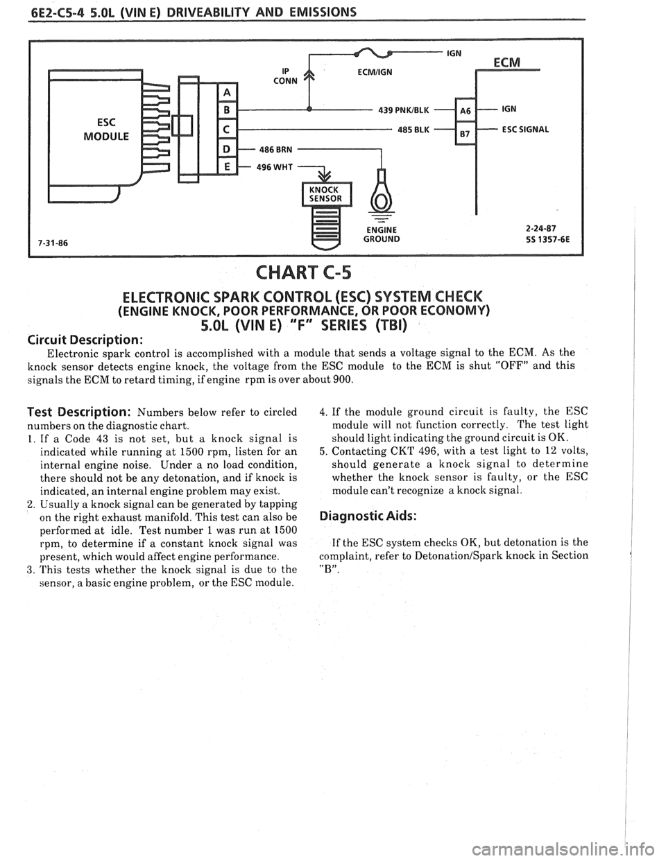
CHART C-5
ELECTRONIC SPARK CONTROL (ESC) SYSTEM CHECK
(ENGINE KNOCK, POOR PERFORMANCE, OR POOR ECONOMV)
5.OL (VIN E) "F" SERIES (TBI)
Circuit Description:
Electronic spark control is accomplished with a module that sends a voltage signal to the ECM. As the
knock sensor detects engine knock, the voltage from the ESC module to the ECM is shut "OFF" and this
signals the ECM to retard timing, if engine rpm is over about 900.
Test Description: Numbers below refer to circled
numbers on the diagnostic chart.
1. If a Code
43 is not set, but a knock signal is
indicated while running at 1500 rpm, listen for an
internal engine noise. Under a no load condition,
there should not be any detonation, and if knock is
indicated, an internal engine problem may exist.
2. Usually a knock signal can be generated by tapping
on the right exhaust manifold. This test can also be
performed at idle. Test number 1 was run at 1500
rpm, to determine if a constant knock signal was
present, which would affect engine performance.
3. This tests whether the knock signal is due to the
sensor, a basic engine problem, or the ESC module.
4. If the module ground circuit is faulty, the ESC
module will not function correctly. The test light
should light indicating the ground circuit is OK.
5. Contacting CKT 496, with a test light to 12 volts,
should generate a knock signal to determine
whether the knock sensor is faulty, or the ESC
module can't recognize a knock signal.
Diagnostic Aids:
If the ESC system checks OK, but detonation is the
complaint, refer to
Detonation1 Spark knock in Section
"B".