1988 PONTIAC FIERO light
[x] Cancel search: lightPage 538 of 1825
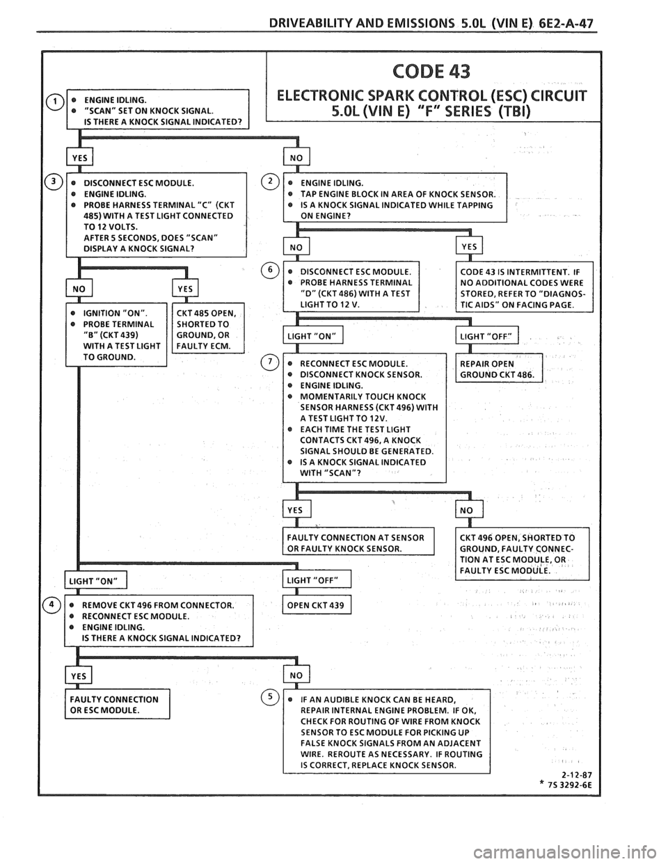
DRIVEABILITY AND EMISSIONS 5.OL (VIN E) 6E2-A-47
IN AREA OF KNOCK SENSOR. 5 TERMINAL "C" (CKT
INDICATED WHILE TAPPING
ST LIGHT CONNECTED
AFTER
5 SECONDS, DOES "SCAN"
@ DISCONNECT KNOCK SENSOR.
ENGINE IDLING.
@ MOMENTARILY TOUCH KNOCK
SENSOR HARNESS (CKT496) WITH
A TEST LIGHTTO 12V. @ EACH TIME THE TEST LIGHT
CONTACTS CKT 496, A KNOCK
Page 546 of 1825
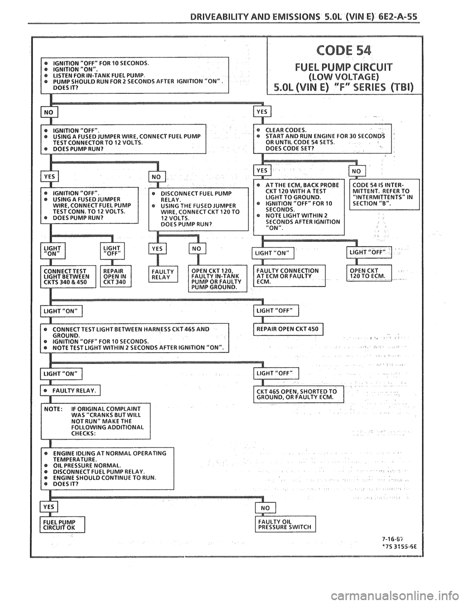
DRlVEABlLlTY AND EMISSIONS 5.Ob (VIN E) 6E2-A-5%
FUEL PUMP CIRCUIT
MPER WIRE, CONNECT FUEL PUMP
TO 12 VOLTS.
CONNECT TEST LIGHT BETWEEN HARNESS
CKT465 AND
EL PUMP RELAY.
Page 547 of 1825
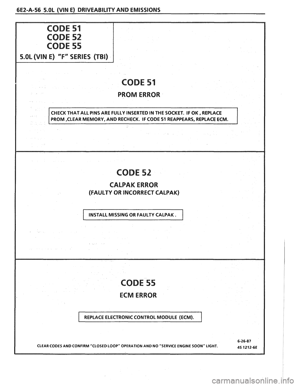
6EZ-A-56 5.OL (VIN E) DRIVEABILITY AND EMISSIONS
S.OL (VIN E) 'T" SERIES (TBI)
CODE 51
PROM ERROR
CODE 52
CALPAK ERROR
(FAULTY OR INCORRECT CALPAK)
CODE 55
ECM ERROR
CLEAR CODES AND CONFIRM "CLOSED LOOP" OPERATION AND NO "SERVICE ENGINE SOON" LIGHT.
INSTALL MISSING OR FAULTY CALPAK .
REPLACE ELECTRONIC CONTROL MODULE (ECM).
Page 549 of 1825
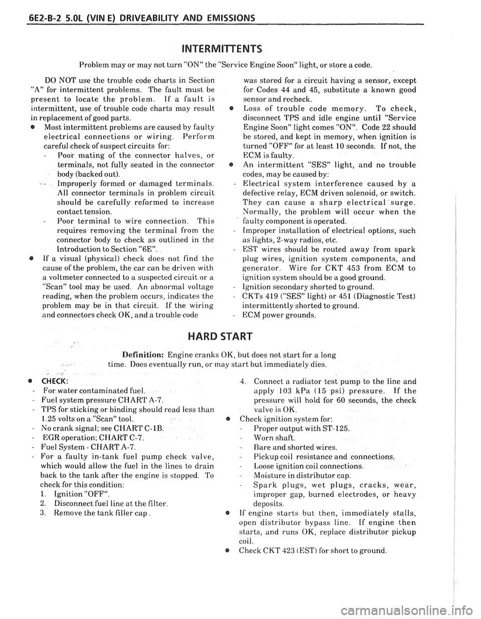
6EZ-B-2 5.OL (VIN E) DRIVEABILITY AND EMISSIONS
Problem may or may not turn "ON" the "Service Engine Soon" light, or store a code.
DO NOT use the trouble code charts in Section
"A" for intermittent problems. The fault must be
present to locate the problem. If a fault is
intermittent, use of trouble code charts may result
in replacement of good parts.
@ Most intermittent problems are caused by faulty
electrical connections or wiring. Perform
careful check of suspect circuits for:
- Poor mating of the connector halves, or
terminals, not fully seated in the connector
body (backed out).
I - Improperly formed or damaged terminals.
All connector terminals in problem circuit
should be carefully reformed to increase
contact tension.
- Poor terminal to wire connection. This
requires removing the terminal from the
connector body to check as outlined in the
Introduction to Section
"6E".
@ If a visual (physical) check does not find the
cause of the problem, the car can be driven with
a voltmeter connected to a suspected circuit or a
"Scan" tool may be used. An abnormal voltage
reading, when the problem occurs, indicates the
problem may be in that circuit. If the wiring
and connectors check OK, and a trouble code was
stored for a circuit having a sensor, except
for Codes 44 and 45, substitute a known good
sensor and recheck.
@ Loss of trouble code memory. To check,
disconnect TPS and idle engine until "Service
Engine Soon" light comes
"ON". Code 22 should
be stored, and kept in memory, when ignition is
turned "OFF" for at least 10 seconds. If not, the
ECM
is faulty.
@ An intermittent "SES" light, and no trouble
codes, may be caused by:
- Electrical system interference caused by a
defective relay, ECM driven solenoid, or switch.
They can cause a sharp electrical surge.
Normally, the problem will occur when the
faulty component is operated.
- Improper installation of electrical options, such
as lights, 2-way radios, etc.
- EST wires should be routed away from spark
plug wires, ignition system components, and
generator. Wire for CKT 453 from ECM to
ignition system should be a good ground.
- Ignition secondary shorted to ground.
- CKTs 419 ("SES" light) or 451 (Diagnostic Test)
intermittently shorted to ground.
- ECM power grounds.
HARD START
Definition: Engine cranks OK, but does not start for a long
time. Does eventually run, or may start but immediately dies.
, <
@ CHECK: 4. Connect a radiator test pump to the line and
- For water contaminated fuel. apply 103 kPa (15 psi) pressure. If the
- Fuel system pressure CHART A-7. pressure will hold for 60 seconds, the check
- TPS for sticking or binding should read less than
valve is OK.
1.25 volts on a "Scan" tool. @ Check ignition system for:
- No crank signal; see CHART C-1B. - Proper output with ST-125.
- EGR operation; CHART C-7. - Worn shaft.
- Fuel System - CHART A-7. - Rare and shorted wires.
- For a faulty in-tank fuel pump check valve, - Pickup coil resistance and connections.
which would allow the fuel in the lines to drain
- Loose ignition coil connections.
back to the tank after the engine is stopped. To
- Moisture in distributor cap.
check for this condition:
- Spark plugs, wet plugs, cracks, wear,
1. Ignition "OFF".
improper gap, burned electrodes, or heavy
2. Disconnect fuel line at the filter
deposits.
3. Remove the tank filler cap. @ If engine starts but then, immediately stalls,
open distributor bypass line. If engine then
starts, and runs OK, replace distributor pickup
coil.
@ Check CKT 423 (EST) for short to ground.
Page 555 of 1825
6EZ-C-1 5.OL (VIN E) DRIVEABILITY AND EMISSIONS
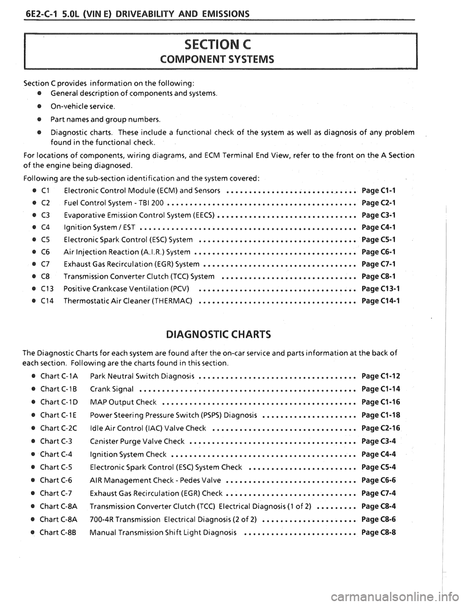
Section C provides information on the following:
@ General description of components and systems.
@ On-vehicle service.
@ Part names and group numbers.
@ Diagnostic charts. These include a functional check of the system as well as diagnosis of any problem
found in the functional check.
For locations of components, wiring diagrams, and ECM Terminal End View, refer to the front on the A Section
of the engine being diagnosed.
Following are the sub-section identification and the system covered:
@ C1 Electronic Control Module (ECM) and Sensors ............................. Page C1-1
@ C2 Fuel Control System - TBI 200 .......................................... Page C2-1
Evaporative Emission Control System (EECS) ...............................
Ignition System 1 EST ................................................
Electronic Spark Control (ESC) System ...................................
Air Injection Reaction (A.I.R.) System ....................................
Exhaust Gas Recirculation (EGR) System ..................................
Transmission Converter Clutch (TCC) System ..............................
Positive Crankcase Ventilation (PCV) ...................................
Thermostatic Air Cleaner (THERMAC) ...................................
BIAGNOSIIC CHARTS
Page C3-1
Page C4-1
Page C5-1
Page C6-1
Page C7-1
Page C8-1
Page C13-1
Page C14-1
The Diagnostic Charts for each system are found after the on-car service and parts information at the back of
each section. Following are the charts found in this section.
@ Chart C-1A Park Neutral Switch Diagnosis ................................... Page C1-12
@ Chart C-1B Crank Signal ................................................ Page C1-14
@ Chart C-1 D MAP Output Check ........................................ Page C1-16 I
..................... @ Chart C-1 E Power Steering Pressure Switch (PSPS) Diagnosis Page C1-18 1
................................ @ Chart C-2C Idle Air Control (IAC) Valve Check Page C2-16 !
..................................... @ Chart C-3 Canister Purge Valve Check Page C3-4 I
@ Chart C-4 Ignition System Check ......................................... Page C4-4
........................ @ Chart C-5 Electronic Spark Control (ESC) System Check Page C5-4
- ............................. @ Chart C-6 AIR Management Check Pedes Valve Page C6-6
............................. Chart C-7 Exhaust Gas Recirculation (EGR) Check Page C7-4
@ Chart C-8A Transmission Converter Clutch (TCC) Electrical Diagnosis (1 of 2) ......... Page C8-4 I
@ Chart C-8A 700-4R Transmission Electrical Diagnosis (2 of 2) ..................... Page C8-6 I
......................... @ Chart C-8B Manual Transmission Shift Light Diagnosis Page C8-8
Page 556 of 1825
DRIVEABILITY AND EMISSIONS 5.OL (VIN El 6EZ-C1-1
SECTION Cl
ELECTWONllC CONTROL MODULE (ECM) AND SENSORS
CONTENTS
GENERAL DESCRIPTION . . . . . . . . . . . . . . . C1-1 Coolant Temperature Sensor . . . . . . . . C1-5
ELECTRONIC CONTROL MODULE (ECM) . . C1-1 MAT Sensor. . . . . . . . . . . .. . . ... . . . . $1 -5
PROM ........................... C1-1 MAP Sensor. . . . . . . . . . . . . . . . . . . . . . C1 -6
CALPAK.........,................ C1-2 Oxygen (02) Sensor. . . . . . ... . . . a C1-6
ECM FUNCTION . . . , . . . . . . . . . . . . . . . . C1-2 Throttle Position Sensor (TPS) . . . . . . . . C1-6
INFORMATION SENSORS . . . . . . . . . . . . . C1-2 Vehicle Speed Sensor (VSS) . . . . . . . . . C1-6
Engine Coolant Temperature Sensor . . C1-2 PIN Switch. . . . . . . . . . . . . . . . . . . . . . . C1-6
MAP Sensor. . . . . . . . . . . . . . . . . . . . . . C1-2 (PSPS) . . . . . ... .. . . . ... . . .. .. . . . C1-6
MAT Sensor. . . . . . . . . . . . . . . . . . . . . . C1-3 AJC Request Signal . . . . . . . . . . . . . . . . C1-6
Oxygen (Oz) Sensor. . . . . . . . . .. . . . . . C1-3 Distributor Reference Signal . . . . . . . . . C1-6
Throttle Posit~on Sensor (TPS) . . . . . . . . C1-3 Knock Signal . . . . . . . . . . . . . . . . . . . C1-6
Knock Sensor . . . . . . . . . . . . . . . . . . . . C1-4 ON-CAR SERVICE . . . . . . . . . . . . . . . . . . . . . C1-6
Park Neutral Switch (Auto Only) . . . . . . C1-4 ELECTRONIC CONTROL MODULE . . . . . . . 61-6
Crank Signal . . . . . . , . . . . . . . . . . . . . . C1-4 PROM ........................... C1-7
A/C "On" Signal . . . , . . . . . . . . . . . . . . C1-4 Functional Check . . . . . . . . . . . . . . . . . C1-8
Vehicle Speed Sensor (VSS) . . . . . . . . . C1-4 CALPAK...................,...... C1-8
Distributor Reference Signal . . . . . . . . . C1-4 COOLANTSENSOR .. . . . . . . . , . . . . . . . . . C1-9
(PSPS) . . . . . . . . . . . . . . . . . . . . . . . . . C1-4 MAPSENSOR ..... ........ ... . .. . .* C1-9
DIAGNOSIS . . . . . . . . . . . . . . . . . . . . . . . . . C1-5 OXYGEN (02) SENSOR . . . . . . . . . a . . a . . C1-9
ECM ............................. C1-5 THROTTLE POSITION SENSOR (TPS) . . . . . C1-10
PROM ........................... C1-5 PARKINEUTRALSWITCH . . . . . . . . . . . . . . C1-10
ECM INPUTS.. . . . . . . . . . . . . . . . , . . . . . C1-5 PARTS
INFORMATION . . . . . . . . . . . . . . . . . C1-10
GENERAL DESCRIPTION
ELECTRONIC CONTROL MODULE (ECM)
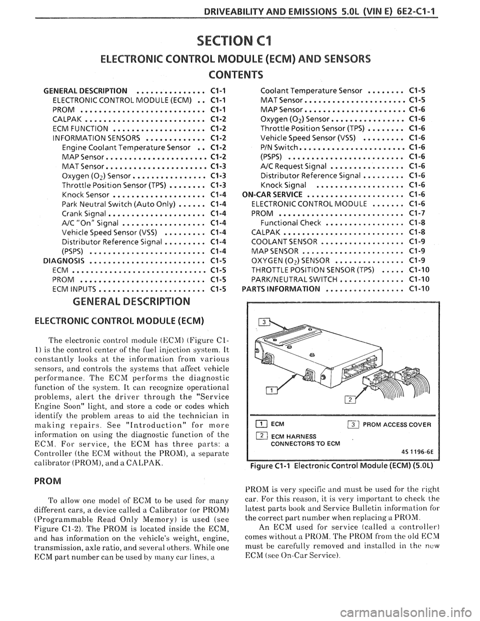
The electronic control module (KCMI (Figure C1-
1) is the control center of the fuel ir!jection system. It
constantly looks at the information from various
sensors, and controls the systems that affect vehicle
performance. The ECM performs the diagnostic
function of the system. It can recognize operational
problems, alert the driver through the "Service
Engine Soon" light, and store a code or codes which
identify the problem areas to aid the technician in
making repairs. See "Introduction" for more
information on using the diagnostic function of the
ECM. For service, the ECM has three parts:
a
Controller (the ECM without the PROM), a separate
calibrator (PROM), and a
CALPAK.
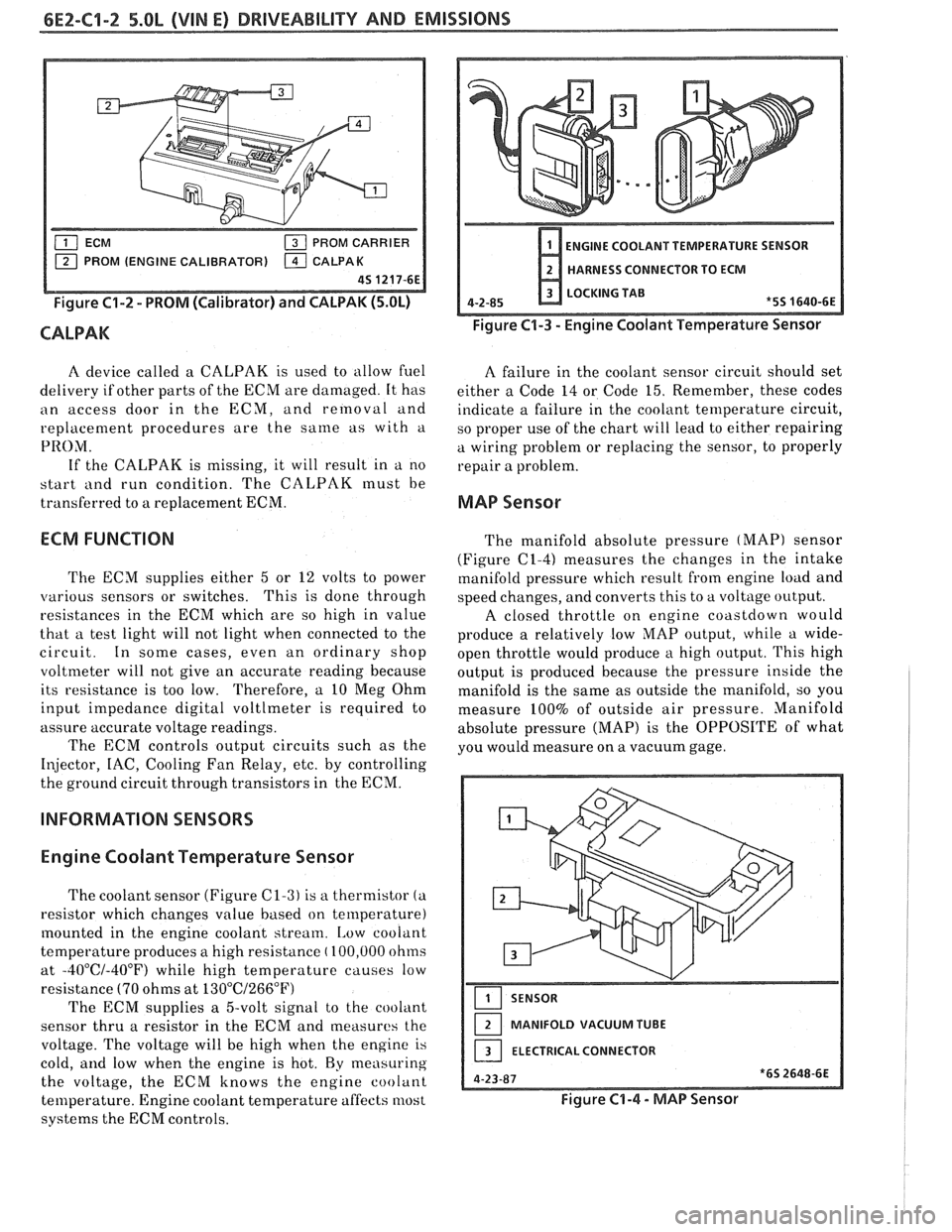
To allow one model of ECM to be used for many
different cars, a device called a Calibrator (or PROM)
(Programmable Read Only Memory) is used (see
Figure
C1-2). The PROM is located inside the ECM,
ancl has information on the vehicle's weight, engine,
transmission, axle ratio, and several others. While one
ECM part number can be used by many car lines, a
ECM PROM ACCESS COVER
1 ECM HARNESS
CONNECTORS TO ECM
45 1196-6E
Figure C1-1 Electronic Control Module (ECM) (5.OL)
PROM is very specific and must be used for the right
car. For this reason, it is very important to checlc the
latest parts book and Service Bulletin information for
the correct part number when replacing
a PROM.
An ECM used for service (called a controller)
comes without a
PROM. The PROM from the old blC>1
must be carefully removed and installctl in the new
EChI (see On-Car Service).
Page 557 of 1825
6EZ-C1-2 5.OL (VIN E) DRIVEABILITY AND EMISSIONS
PROM CARRIER
PROM (ENGINE CALIBRATOR)
Figure C1-2 - PROM (Calibrator) and CALPAK (5.OL)
CALPAK
ENGINE COOLANT TEMPERATURE SENSOR
HARNESS CONNECTOR TO ECM
LOCKING TAB
4-2-85
*5S 1640-6E
Figure C1-3 - Engine Coolant Temperature Sensor
A device called a CALPAK is used to allow fuel
A failure in the coolant sensor circuit should set
delivery if other parts of the ECM are damaged. It has
either a Code 14 or Code 15. Remember, these codes
an access door in the ECM, and removal and
indicate a failure in the coolant temperature circuit,
replacement procedures are the
same as with a
so proper use of the chart will lead to either repairing
PRO;\/I. a wiring problem or replacing the sensor, to properly
If the CALPAK is missing, it will result in a no
repair a problem.
start
i111d run condition. The CALPAK must be
transferred to a replacement ECM.
MAP Sensor
ECM FUNCTION
The ECM supplies either 5 or 12 volts to power
various sensors or switches. This
is done through
resistances in the ECM which are so high in value
that a test light will not light when connected to the
circuit. In some cases, even an ordinary shop
voltmeter will not give an accurate reading because
its resistance is too low. Therefore, a 10 Meg Ohm
input impedance digital voltlmeter is required to
assure accurate voltage readings.
The ECM controls output circuits such as the
Injector, IAC, Cooling Fan Relay, etc. by controlling
the ground circuit through transistors in the ECM.
INFORMATION SENSORS
Engine Coolant Temperature Sensor
The coolant sensor (Figure C1-3) is a thermistor (a
resistor which changes value based on temperature)
mounted in the engine coolant stream.
[,ow coolant
temperature produces a high resistance
( 100,000 ohms
at
-40°C/-40°F) while high temperature causes low
resistance
(70 ohms at 13O0C/266"F)
The ECM supplies a 5-volt signal to the cooliint
sensor thru a resistor in the ECM and measures the
voltage. The voltage will be high when the engine is
cold,
and low when the engine is hot. By measuring
the voltage, the ECM knows the engine coolant
temperature. Engine coolant temperature affects most
systems the ECM controls. The
manifold absolute pressure
(MAP) sensor
(Figure
(21-4) measures the changes in the intake
manifold pressure which result from engine load and
speed changes, and converts this to a voltage output.
A closed throttle on engine coastdown would
produce a relatively low
MAP output, while a wide-
open throttle would produce a high output. This high
output is produced because the pressure inside the
manifold is the same as outside the manifold, so you
measure 100% of outside air pressure. Manifold
absolute pressure (MAP) is the OPPOSITE of what
you would measure on a vacuum gage.
SENSOR
MANIFOLD VACUUM TUBE
ELECTRICAL CONNECTOR
Figure C1-4 - MAP Sensor
Page 559 of 1825
6EZ-C1-4 S.OL (VIN E) DRIVEABILITY AND EMISSIONS
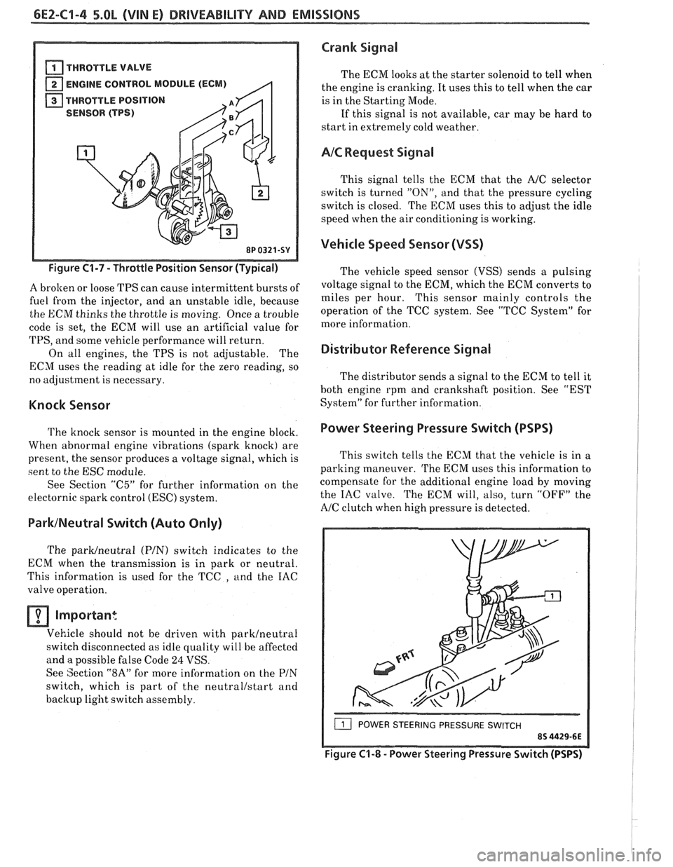
THROTTLE VALVE
ENGINE CONTROL MODULE (ECM)
THROTTLE POSITION
(TPS)
8P 0321.
Figure C1-7 - Throttle Position Sensor (Typical)
A brolten or loose TPS can cause intermittent bursts of
fuel from the injector, and an unstable idle, because
the ECM thinks the throttle is moving. Once a trouble
code is set, the ECM will use an artificial value for
TPS, and some vehicle performance will return.
On all engines, the TPS is not adjustable. The
ECM uses the reading at idle for the zero reading, so
no adjustment is necessary.
Knock Sensor
The knock sensor is mounted in the engine block.
When abnormal engine vibrations (spark knock) are
present, the sensor produces a voltage signal, which is
sent to the ESC module.
See Section
"C5" for further information on the
electornic spark control
(ESC) system.
ParklNeutral Switch (Auto Only)
The parWneutra1 (PIN) switch indicates to the
ECM when the transmission is in park or neutral.
This information is used for the TCC
, and the IAC
valve operation.
Important
Vehicle should not be driven with parklneutral
switch disconnected as idle quality will be affected
and a possible false Code
24 VSS.
See Section
"8A" for more information on the PIN
switch, which is part of the neutrallstart and
backup light switch assembly.
Crank Signal
The ECM looks at the starter solenoid to tell when
the engine is cranking. It uses this to tell when the car
is in the Starting Mode.
If this signal is not available, car may be hard to
start in extremely cold weather.
AIC Request Signal
This signal tells the ECM that the AJC selector
switch is turned
"ON", and that the pressure cycling
switch is closed. The ECM uses this to adjust the idle
speed when the air conditioning is working.
Vehicle Speed Sensor (VSS)
The vehicle speed sensor (VSS) sends a pulsing
voltage signal to the ECM, which the ECM converts to
miles per hour. This sensor mainly controls the
operation of the TCC system. See "TCC System" for
more information.
Distributor Reference Signal
The distributor sends a signal to the ECM to tell it
both engine rpm and crankshaft position. See "EST
System" for further information.
Power Steering Pressure Switch (PSPS)
I
This switch tells the ECM that the vehicle is in a
parking maneuver.
The ECM uses this information to
compensate for the additional engine load by moving
the IAC valve. The ECM will, also, turn
"OFF" the
A/C clutch when high pressure is detected.
( POWER STEERING PRESSURE SWITCH
Figure C'I-8 - Power Steering Pressure Switch (PSPS)