1988 PONTIAC FIERO light
[x] Cancel search: lightPage 415 of 1825
BB.4 ENGINE COOLING
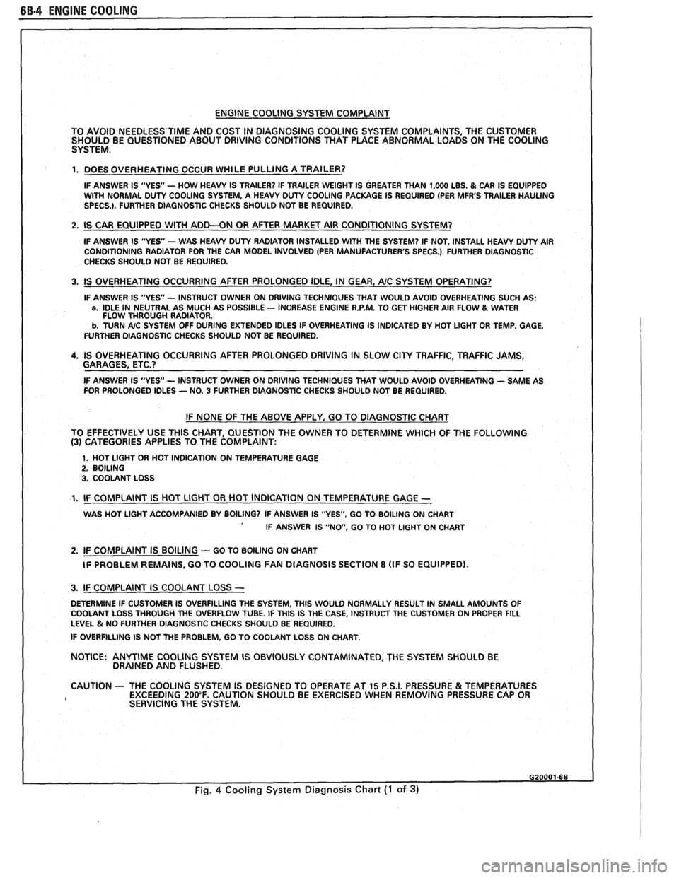
ENGINE COOLING SYSTEM COMPLAINT
TO AVOID NEEDLESS
TIME AND COST IN DIAGNOSING COOLING SYSTEM COMPLAINTS, THE CUSTOMER
SHOULD BE QUESTIONED ABOUT DRIVING CONDITIONS THAT PLACE ABNORMAL LOADS ON THE COOLING
SYSTEM.
1. DOES OVERHEATING OCCUR WHILE PULLING A TRAILER?
IF ANSWER IS "YES'- HOW HEAVY IS TRAILER? IF TRAILER WEIGHT IS GREATER THAN 1,000 LBS. & CAR IS EQUIPPED
WITH NORMAL DUTY COOLING SYSTEM, A HEAVY DUTY COOLING PACKAGE IS REQUIRED (PER MFR'S TRAILER HAULING
SPECS.). FURTHER DIAGNOSTIC CHECKS SHOULD NOT BE REQUIRED.
2. IS CAR EQUIPPED WlTH ADD-ON OR AFTER MARKET AIR CONDITIONING SYSTEM?
IF ANSWER IS "YES"- WAS HEAVY DUTY RADIATOR INSTALLED WITH THE SYSTEM? IF NOT, INSTALL HEAVY DUTY AIR
CONDITIONING RADIATOR FOR THE CAR MODEL INVOLVED (PER MANUFACTURER'S SPECS.). FURTHER DlAGNOSTlC
CHECKS SHOULD NOT BE REQUIRED.
3. IS OVERHEATING OCCURRING AFTER PROLONGED IDLE, IN GEAR, AIC SYSTEM OPERATING?
IF ANSWER IS "YES - INSTRUCT OWNER ON DRIVING TECHNIQUES THAT WOULD AVOID OVERHEATING SUCH AS: a, IDLE IN NEUTRAL AS MUCH AS POSSIBLE - INCREASE ENGINE R.P.M. TO GET HIGHER AIR FLOW & WATER
FLOW THROUGH RADIATOR.
b. TURN A/C SYSTEM OFF DURING EXTENDED IDLES IF OVERHEATING IS INDICATED BY HOT LIGHT OR TEMP. GAGE.
FURTHER DIAGNOSTIC CHECKS SHOULD NOT BE REQUIRED.
4. IS OVERHEATING OCCURRING AFTER PROLONGED DRIVING IN SLOW CITY TRAFFIC, TRAFFIC JAMS,
GARAGES, ETC.?
IF ANSWER IS "YES - INSTRUCT OWNER ON DRIVING TECHNIQUES THAT WOULD AVOID OVERHEATING - SAME AS
FOR PROLONGED IDLES - NO. 3 FURTHER DIAGNOSTIC CHECKS SHOULD NOT BE REQUIRED.
IF NONE OF THE ABOVE APPLY, GO TO DIAGNOSTIC CHART
TO EFFECTIVELY USE THlS CHART, QUESTION THE OWNER TO DETERMINE WHICH OF THE FOLLOWING
(3) CATEGORIES APPLIES TO THE COMPLAINT:
1. HOT LlGHT OR HOT INDICATION ON TEMPERATURE GAGE 2. BOILING 3. COOLANT LOSS
1. IF COMPLAINT IS HOT LlGHT OR HOT INDICATION ON TEMPERATURE GAGE -
WAS HOT LlGHT ACCOMPANIED BY BOILING? IF ANSWER IS "YES", GO TO BOILING ON CHART
IF ANSWER IS "NO, GO TO HOT LlGHT ON CHART
2. IF COMPLAINT IS BOILING - GO TO BOILING ON CHART
IF PROBLEM REMAINS, GO TO COOLING
FAN DIAGNOSIS SECTION 8 (IF SO EQUIPPED).
I 3. IF COMPLAINT IS COOLANT LOSS -
DETERMINE IF CUSTOMER IS OVERFILLING THE SYSTEM, THlS WOULD NORMALLY RESULT IN SMALL AMOUNTS OF
I COOLANT LOSS THROUGH THE OVERFLOW TUBE. IF THlS IS THE CASE, INSTRUCT THE CUSTOMER ON PROPER FILL LEVEL & NO FURTHER DIAGNOSTIC CHECKS SHOULD BE REQUIRED.
I IF OVERFILLING IS NOT THE PROBLEM, GO TO COOLANT LOSS ON CHART.
NOTICE:
ANYTIME COOLING SYSTEM IS OBVIOUSLY CONTAMINATED, THE SYSTEM SHOULD BE
DRAINED AND FLUSHED.
1 CAUTION - THE COOLING SYSTEM IS DESIGNED TO OPERATE AT 15 P.S.I. PRESSURE & TEMPERATURES
EXCEEDING 200°F. CAUTION SHOULD BE EXERCISED WHEN REMOVING PRESSURE CAP OR
I SERVICING THE SYSTEM.
Fig. 4 Cooling System Diagnosis Chart (I of 3)
Page 422 of 1825
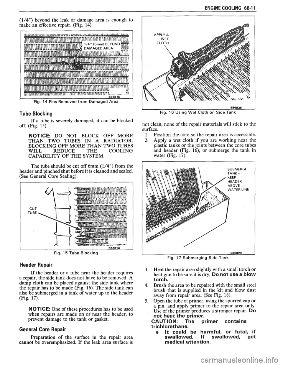
(1/4") beyond the leak or damage area is enough to
make an effective repair. (Fig. 14).
d""U,"
Fig. 14 Fins Removed from Damaged Area
Tube Blocking
If a tube is severely damaged, it can be blocked
off. (Fig. 15).
NOTICE: DO NOT BLOCK OFF MORE
THAN TWO TUBES IN A RADIATOR.
BLOCKING OFF MORE THAN TWO TUBES
WILL REDUCE THE COOLING
CAPABILITY OF THE SYSTEM.
The tube should be cut off 6mm
(1/4") from the
header and pinched shut before it is cleaned and sealed.
(See General Core Sealing).
CUT
TUBE
Fig. 15 Tube Blocking
Header Repair
If the header or a tube near the header requires
a repair, the side tank does not have to be removed.
A
damp cloth can be placed against the side tank where
the repair has to be made (Fig. 16). The side tank can
also be submerged in a tank of water up to the header
(Fig. 17).
NOTICE: One of these procedures has to be used
when repairs are made on or near the header, to
prevent damage to the tank or gasket.
General Gore Repair
Preparation of the surface in the repair area
cannot be overemphasized. If the leak area surface is
ENGINE COOLING 6B-11
Fig. 16 Using Wet Cloth on Side Tank
not clean, none of the repair materials will stick to the
surface.
1. Position the core so the repair area is accessible.
2. Apply a wet cloth if you are working near the
plastic tanks or the joints between the core tubes
and header (Fig. 16); or submerge the tank in
water (Fig. 17).
SUBMERGE TANK -
Fig. 17 Submerging Side Tank
3. Heat the repair area slightly with a small torch or
heat gun to be sure it is dry.
Do not use a blow
torch.
4. Brush
the area to be repaired with the small steel
brush that is supplied in the kit and blow dust
away from repair area. (See Fig. 18).
5. Open
the tube of primer, using the spurred cap or
a pin, and apply primer to the repair area only.
Use of the primer produces a stronger repair.
Do
not heat the primer.
CAUTION: The primer contains
trichlorethane.
aa It could be harmful, or fatal, if
swallowed. If swaIIowed, gel
medical attention.
Page 423 of 1825
88-12 ENGINE COOLING
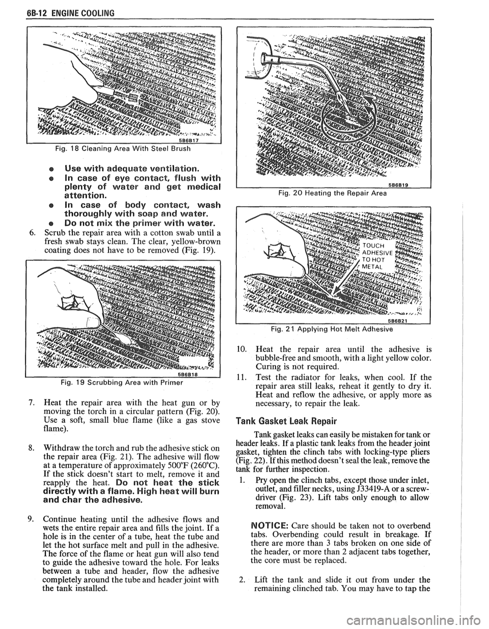
Fig. 18 Cleaning Area With Steel Brush
e Use with adequate ventilation.
In case of eye contact, flush with
plenty of water and get medical
attention.
In case of body
contact, wash
thoroughly with soap
and water.
Do not
mix the primer with water.
6. Scrub the repair area with a cotton swab until a
fresh swab stays clean. The clear, yellow-brown
coating does not have to be removed (Fig. 19).
Fig. 19 Scrubbing Area with Primer
7. Heat the repair area with the heat gun or by
moving the torch in a circular pattern (Fig. 20).
Use a soft, small blue flame (like a gas stove
flame).
8. Withdraw the torch and rub the adhesive stick on
the repair area (Fig. 21). The adhesive will flow
at a temperature of approximately 500°F (260°C).
If the stick doesn't start to melt, remove it and
reapply the heat.
Do not heat the stick
directly with
a flame. High heat will burn
and
char the adhesive.
9. Continue heating until the adhesive flows and
wets the entire repair area and fills the joint. If a
hole is in the center of a tube, heat the tube and
let the hot surface melt and pull in the adhesive.
The force of the flame or heat gun will also tend
to guide the adhesive toward the hole. For leaks
between a tube and header, flow the adhesive
completely around the tube and header joint with
the tank installed.
Fig. 20 Heating the Repair Area
I
Fig. 21 Applying Hot Melt Adhesive I
10. Heat the repair area until the adhesive is
bubble-free and smooth, with a light yellow color.
Curing is not required.
11. Test the radiator for leaks, when cool. If the
repair area still leaks, reheat it gently to dry it.
Heat and
reflow the adhesive, or apply more as
necessary, to repair the leak.
Tank Gasket beak Repair I 1
Tank gasket leaks can easily be mistaken for tank or
header leaks. If a plastic tank leaks from the header joint
gasket, tighten the clinch tabs with locking-type pliers
(Fig. 22). If this method doesn't seal the leak, remove the
tank for further inspection.
1. Pry open the clinch tabs, except those under inlet,
outlet, and filler necks, using
J33419-A or a screw-
driver (Fig.
23). Lift tabs only enough to allow
removal.
NOTICE: Care should be taken not to overbend
tabs. Overbending could result in breakage. If
there are more than
3 tabs broken on one side of
the header, or more than
2 adjacent tabs together,
the core must be replaced.
2. Lift the tank and slide it out from under the
remaining clinched tab. You may have to tap the
Page 444 of 1825
BATTERY 6D1.1
SECTION 6Dl
BATTERY
CONTENTS
.......................... .. General Description ................................ 6D1- 1 Battery Charging ...... 6D 1-2
Battery .......................... ... ....................... 6D 1 - 1 Charging Completely Discharged
.................................................... ............................. Ratings .................... ... 6D 1 - 1 Battery 6D 1-3
........................................... Reserve Capacity ..................................... 6D 1 - 1 Jump Starting 6D
1-4
Cranking ............a*............ 6D1-1 On-Gar Service ...................................... 6Dl-5 .................................. Built-In Hydrometer 6D 1-2 Battery Cable Routing ............................... 6D 1-5 Diagnosis ................................................... 6Dl-2
Specifications .............................................. 6D 1-7 ............................. Service Procedures ..... 6D 1-2
GENERAL DESCRIPTION
The engine electrical system includes the battery,
ignition (primary and secondary), starter (and related
wiring) and the generator (and related wiring).
Diagnostic charts (see Section 6D) will aid in
trouble-shooting system faults. When a fault is traced
to a particular component, refer to that components'
section of the service manual.
BATTERY
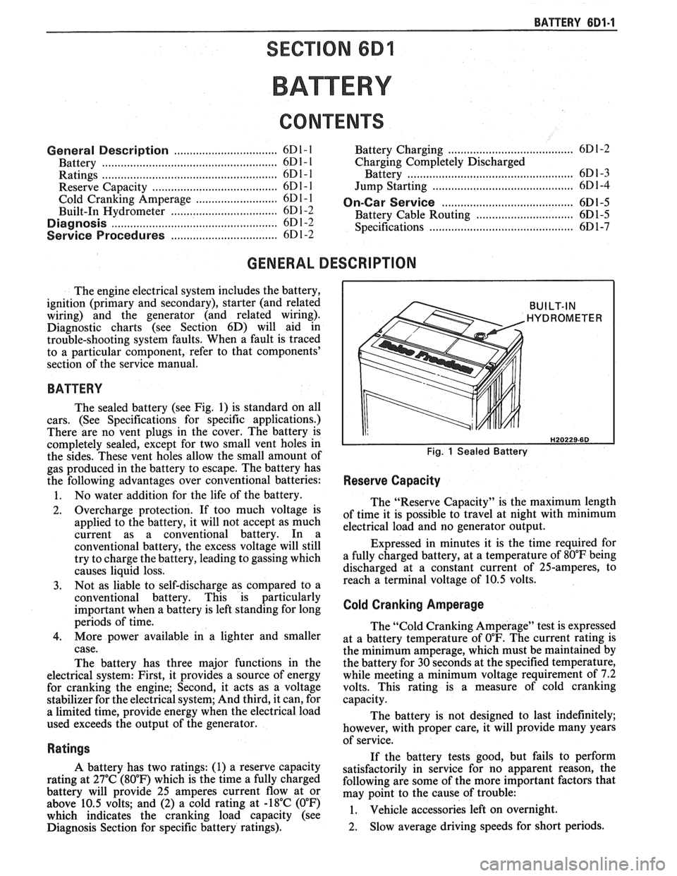
The sealed battery (see Fig. 1) is standard on all
cars. (See Specifications for specific applications.)
There are no vent plugs in the cover. The battery is
completely sealed, except for two small vent holes in
the sides. These vent holes allow the small amount of
gas produced in the battery to escape. The battery has
the following advantages over conventional batteries:
1. No water addition for the life of the battery.
2. Overcharge protection. If too much voltage is
applied to the battery, it will not accept as much
current as a conventional battery. In a
conventional battery, the excess voltage will still
try to charge the battery, leading to gassing which
causes liquid loss.
3. Not as liable to self-discharge as compared to a
conventional battery. This is particularly
important when a battery is left standing for long
periods of time.
4. More power available in a lighter and smaller
case.
The battery has three major functions in the
electrical system: First, it provides a source of energy
for cranking the engine; Second, it acts as a voltage
stabilizer for the electrical system; And third, it can, for
a limited time, provide energy when the electrical load
used exceeds the output of the generator.
Ratings
A battery has two ratings: (1) a reserve capacity
rating at 27°C (80°F) which is the time a fully charged
battery will provide 25 amperes current flow at or
above 10.5 volts; and (2) a cold rating at -18°C (0°F)
which indicates the cranking load capacity (see
Diagnosis Section for specific battery ratings).
BUILT-IN
HYDROMETER
Fig. 1 Sealed Battery
Reserve Capacity
The "Reserve Capacity" is the maximum length
of time it is possible to travel at night with minimum
electrical load and no generator output.
Expressed in minutes it is the time required for
a fully charged battery, at a temperature of 80°F being
discharged at a constant current of 25-amperes, to
reach a terminal voltage of 10.5 volts.
Cold Cranking Amperage
The "Cold Cranking Amperage" test is expressed
at a battery temperature of
0°F. The current rating is
the minimum amperage, which must be maintained by
the battery for 30 seconds at the specified temperature,
while meeting a minimum voltage requirement of 7.2
volts. This rating is a measure of cold cranking
capacity.
The battery is not designed to last indefinitely;
however, with proper care, it will provide many years
of service.
If the battery tests good, but fails to perform
satisfactorily in service for no apparent reason, the
following are some of the more important factors that
may point to the cause of trouble:
1. Vehicle
accessories left on overnight.
2. Slow
average driving speeds for short periods.
Page 445 of 1825
6D1-2 BA'TTERY
3. The
vehicle's electrical load is more than the
generator output, particularly with the addition
of aftermarket equipment.
4. Defects in the charging system such as electrical
shorts, slipping fan belt, faulty generator, or
faulty voltage regulator.
5. Battery abuse, including failure to keep the
battery cable terminals clean and tight, or loose
battery hold-down. See "Service Procedures" for
torque specifications.
6. Mechanical problems in the electrical system,
such as shorted or pinched wires.
Electrolyte Freezing
The freezing point of electrolyte depends on its
specific gravity. Since freezing may ruin a battery, it
should be protected against freezing by keeping it in a
charged condition.
Carrier and Hold-Down
The battery carrier and hold-down clamp should
be clean and free from corrosion before installing
battery.
The carrier should be in sound condition, to hold
the battery securely and keep it level. Make certain
there are no parts in the carrier before installing
battery.
To prevent the battery from shaking
in its carrier,
the hold-down bolts should be tight, but not
overtightened.
Built-In Hydrometer
The sealed battery has a built-in, temperature
compensated hydrometer in the top of the battery. This
hydrometer is to be used with the following diagnostic
procedure.
When observing the hydrometer, make sure that
the battery has a clean top. A light may be required,
if the lighting is poor.
Under normal operation, two indications can be
observed (see Fig.
4).
1. GREEN DOT VISIBLE
Any green appearance is interpreted as a "green
dot" and the battery
is ready for testing.
2. DARK; GREEN DOT NOT VISIBLE
If there is a cranking complaint, the battery
should be tested as described in the "Diagnosis"
section. The charging and electrical system
should also be checked at this time.
Occasionally, a third condition may appear:
3. CLEAR OR LIGHT YELLOW
This means the fluid level is below the bottom of
the hydrometer. This may have been caused by
excessive or prolonged charging, a broken case,
excessive tipping, or normal battery
wearout.
Finding a battery in this condition may indicate
high charging voltages caused by a faulty
charging system. Therefore, the charging and
electrical systems may need to be checked. If a
cranking complaint exists and is caused by the
battery, it should be replaced.
BATTERY
1. VISUAL INSPECTION
Check for obvious damage, such as cracked or
broken case or cover, that could permit loss of
electrolyte. If obvious damage is noted, replace
the battery. Determine cause of damage and
correct as needed. If not, proceed to step 2.
2. HYDROMETER CHECK
a. GREEN
DOT VISIBLE
- Go To Step 3
b. DARK;
GREEN DOT NOT VISIBLE -
Charge the battery as outlined under
"Charging Procedure" section and proceed
to Step 3.
3. LOAD TEST
Load testing may require use of battery side
terminal adapters to insure good connections (see
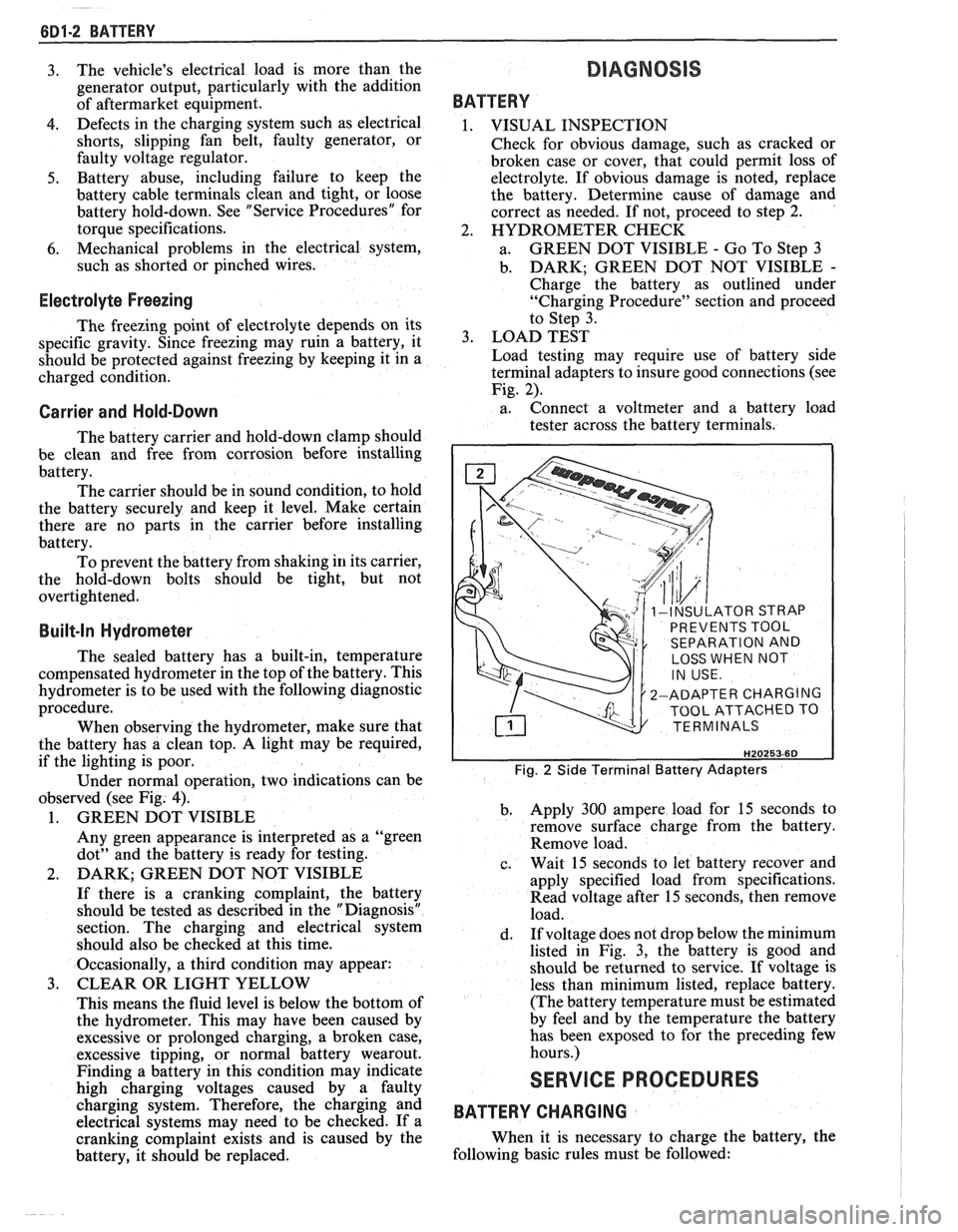
Fig. 2).
a. Connect
a voltmeter and a battery load
tester across the battery terminals.
INSULATOR STRAP
PREVENTS TOOL
SEPARATION AND
LOSS WHEN NOT
2-ADAPTER CHARGING
TOOL ATTACHED TO
TERMINALS
Fig. 2 Side Terminal Battery Adapters
b. Apply 300 ampere load for 15 seconds
to
remove surface charge from the battery.
Remove load.
c. Wait
15 seconds to let battery recover and
apply specified load from specifications.
Read voltage after 15 seconds, then remove
load.
d. If
voltage does not drop below the minimum
listed in Fig. 3, the battery is good and
should be returned to service. If voltage is
less than minimum listed, replace battery.
(The battery temperature must be estimated
by feel and by the temperature the battery
has been exposed to for the preceding few
hours.)
SERVICE PROCEDURES
BATTERY CHARGING
When it is necessary to charge the battery, the
following basic rules must be followed:
Page 446 of 1825
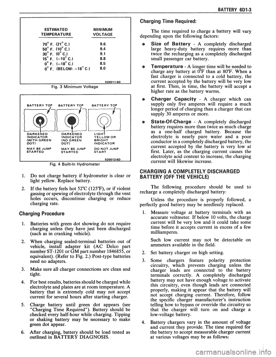
ESTIMATED MINIMUM
TEMPERATURE VOLTAGE
70' F. (21' C.) 9.6
50' F. (10' C.) 9.4
30' F. (0' C;) 9.1
15' F. (-10 C.) 8.8
o0 F. (-18' C.) 8.5
0' F. (BELOW: -18' c.) 8.0
Fig. 3 Minimum Voltage
BATTERY TOP BATTERY TOP BATTERY TOP
DARKE~ED DARK'ENED LIGH? INDICATOR INDICABOR YELLOW OR
(WITH GREEN (NO
GREEN BRIGHT
DOT)
DOT) INDICATOR
MAY BE
JUMP MAY BE JUMP DO NOT JUMP
STARTED STARTED START
Fig. 4 Built-In Hydrometer
1. Do not charge battery if hydrometer is clear or
light yellow. Replace battery.
2. If the battery feels hot 52°C
(125"F), or if violent
gassing or spewing of electrolyte through the vent
holes occurs, discontinue charging or reduce
charging rate.
Charging Procedure
1. Batteries with green
dot showing do not require
charging unless they have just been discharged
(such as in cranking vehicle).
2. When charging sealed-terminal batteries out of
vehicle, install adapter kit (AC Delco part
number ST-1201 or GM part number 1846855, or
equivalent). (Refer to Fig. 2.) Post-type batteries
need no adapters.
3. Make sure all charger connections are clean and
tight.
4. For
best results, batteries should be charged while
electrolyte and plates are at room temperature. A
battery that is extremely cold may not accept
current for several hours after starting charger.
5. Charge battery until green dot appears (see
"Charging Time Required"). Battery should be
checked every half-hour while charging. Tipping
or shaking battery may be necessary to make
green dot appear.
6. After charging, battery should be load tested as
outlined in BATTERY DIAGNOSIS.
BATTERY 681-3
Charging Time Required:
The time required to charge a battery will vary
depending upon the following factors:
e Size sf Battery - A completely discharged
large heavy-duty battery requires more than
twice the recharging as a completely discharged
small passenger car battery.
Temperature - A longer time will be needed to
charge any battery at
O"F than at 80°F. When a
fast charger is connected to a cold battery, the
current accepted by the battery will be very low
at first. Then, in time, the battery will accept a
higher rate as the battery warms.
Charger Capacity - A charger which can
supply only five amperes will require a much
longer period of charging than a charger that can
supply
30 amperes or more.
e State-Of-Charge - A completely discharged
battery requires more than twice as much charge
as a one-half charged battery. Because the
electrolyte is nearly pure water and a poor
conductor in a completely discharged battery, the
current accepted by the battery is very low at
first. Later, as the charging current causes the
electrolyte acid content to increase, the charging
current will likewise increase.
CHARGING A COMPLETELY DISCHARGED
BATTERY
(OFF THE VEHICLE)
The following procedure should be used to
recharge a completely discharged battery:
Unless the procedure is properly followed, a
perfectly good battery may be needlessly replaced.
1. Measure voltage at battery terminals with an
accurate voltmeter. If below 10 volts, the charge
current will be very low and it could take some
time before it accepts current in excess of a few
milliamperes.
Such low current may not be detectable on
ammeters available in the field.
2. Set battery charger on high setting.
3. Some chargers feature polarity protection
circuitry, which prevents charging unless the
charger leads are connected to the battery
terminals correctly. A completely discharged
battery may not have enough voltage to activate
this circuitry, even though leads are connected
properly, making it appear that the battery will
not accept charging current. Therefore, follow
the specific charger manufacturer's instruction
telling how to bypass or override the circuitry so
that the charger will turn on and charge a
low-voltage battery.
4. Battery chargers vary in the amount of voltage
and current they provide. The time required for
the battery to accept measurable charger current
at various voltages may be as follows:
Page 447 of 1825
6D1-4 BATTERY
VOLTAGE
A. 16.0 or more
B. 14.0
- 15.9
C. 13.9 or less HOURS
1. Set parking brake and place automatic
Up to 4 Hours transmission in "PARK" (NEUTRAL for
Up to 8 Hours manual transmission.) Turn off the ignition,
Up to 16 Hours turn off lights, and all other electrical
If the charge current is still not
measurable
at the end of the above charging
times, the battery should be replaced.
If the charge current is measurable during
the charging time, the battery is considered to be
good and charging should be completed in the
normal manner.
5. It
is important to remember that a completely
discharged battery must be recharged for a
sufficient number of ampere hours (AH) to
restore it to a usable state. As a general rule of
thumb, using the reserve capacity rating (RC) of
the battery as the number of ampere hours of
charge will usually bring the green dot into view.
For example, if battery is rated at 75 RC minutes,
it would be completely recharged as follows:
10 ampere charge x 7-1/2 hours
= 75 AH
25 ampere charge x 3 hours = 75 AH, etc.
6. It
is recommended that any battery recharged by
this procedure be
LOAD TESTED to establish
serviceability.
JUMP STARTING IN CASE OF EMERGENCY
WITH AUXILIARY (BOOSTER) BAVEEWY
NOTICE: Do not push or tow the vehicle to start.
Damage to the emission system, or to other parts
of the vehicle may result.
Both booster and discharged battery should be
treated carefully when using jumper cables. Follow the
procedure outlined below, being careful not to cause
sparks:
CAUTION: Departure from these
conditions or the procedure below
could result in:
(1) Serious personal
injury (particularly to eyes) or property
damage from such causes as battery
explosion, battery acid, or electrical
burns; and/or
(2) damage to electronic
components of either vehicle.
Never expose battery to open flame or electric
spark
- batteries generate a gas which is flammable and
explosive.
Remove rings, watches, and other jewelry. Wear
approved eye protection.
Do not allow battery fluid to contact eyes, skin,
fabrics, or painted surfaces
- fluid is a corrosive acid.
Flush any contacted area with water immediately and
thoroughly. Be careful that metal tools or jumper
cables do not contact the positive battery terminal (or
metal in contact with it) and any other metal on the
car, because a short circuit could occur. Batteries
should always be kept out of the reach of children.
loads.
2. Check the built-in hydrometer. If it is clear or
light yellow, replace the battery.
3. Attach the end of one jumper cable to the positive
terminal of the booster battery and the other end
of the same cable to the positive terminal of the
discharged battery. Do not permit vehicles to
touch each other as this could cause a ground
connection and counteract the benefits of this
procedure. (Use 12-volt battery only to jump start
the engine).
4. Attach one end of the remaining negative cable
to the negative terminal of the booster battery,
and the other end to a solid engine ground (such
as
A/C compresser bracket or generator
mounting bracket) at least 18 inches from the
battery of the vehicle being started (DO NOT
CONNECT DIRECTLY TO THE NEGATIVE
TERMINAL OF THE DEAD BATTERY).
5. Start the engine of the vehicle that is providing
the jump start and turn off electrical accessories.
Then start the engine in the car with the
discharged battery.
6. Reverse these directions exactly when removing
the jumper cables. The negative cable must be
disconnected from the engine that was jump
started first.
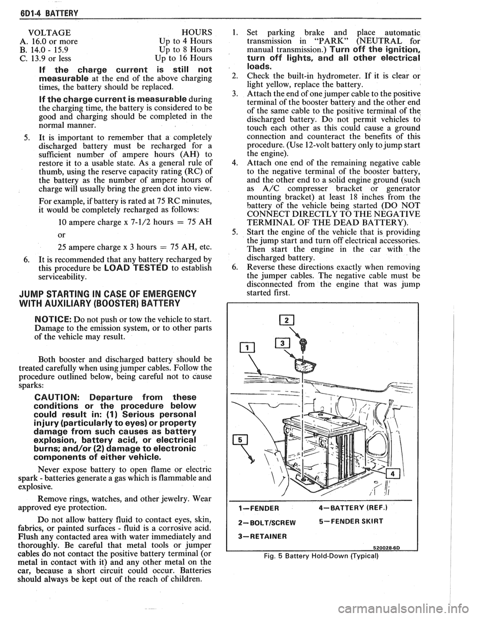
I-FENDER 4-BATTERY (REF.)
2- BOLTISCREW 5-FENDER SKIRT
3-RETAINER
520028-60
Fig. 5 Battery Hold-Down (Typical)
Page 460 of 1825
CRANKING SYSTEM BD2-9
I TESTING SERIES COIL FOR OPEN I
TESTING SOLENOID WINDINGS
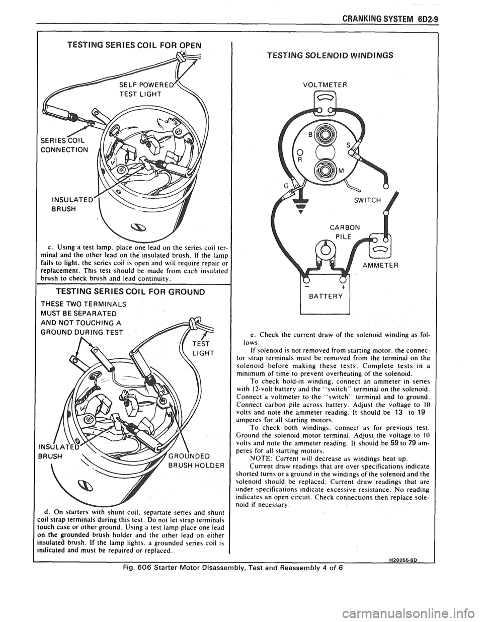
c. Us~ng a test lamp. place onelead on the series coil ter-
minal and the other lead on the insulated brush. If the lamp
fails to light. the series coil is open and will require repair or
replacement. This test should be made from each insulated
brush to check brush and lead continuity.
TESTING SERIES COlL FOR GROUND
THESE TWO TERMINALS
MUST BE SEPARATED
d. On starters
withshunt coil. sepanate series and shunt
coil strap terminals during this test. Do not let strap terminals
touch case or other ground. Using a test lamp place one lead
on
he grounded brush holder and the other lead on either
insulated brush. If the lamp lights, a grounded series coil is
indicated and must be repaired or replaced. VOLTMETER
e. Check the current draw of the solenoid winding as fol-
lows:
If solenoid is not removed from starting motor. the connec-
tor
strap terminals must be removed from the terminal on the
solenoid before making these tests. Complete tests in a
minimum of time to prevent overheating of the solenoid.
To check hold-in winding, connect an ammeter in series
with 12-volt battery and the "switch" terminal on the solenoid.
Connect a voltmeter to the "switch" terminal and to ground.
Connect carbon pile across battery. Adjust the voltage to
10 volts and note the ammeter reading. It should be 13 to 19 amperes for all starting motors.
To check both windings. connect as for previous test.
Ground the solenoid motor terminal. Adjust the voltage to 10
volts and note the ammeter reading. It should be
59 to 79 am-
peres for all starting motors.
NOTE: Current will decrease as windings heat up.
Current draw readings that are over specifications indicate
shorted turns or a ground in the windings of the solenoid and the
solenoid should be replaced. Current draw readings that are
under specifications indicate excessive resistance. No reading
indicates an open circuit. Check connections then replace sole-
noid if necessary.
H20255.6D
Fig. 606 Starter Motor Disassembly, Test and Reassembly 4 of 6