1988 PONTIAC FIERO light
[x] Cancel search: lightPage 327 of 1825
5B6-6 DISC BRAKE CALIPER ASSEMBLY
e Use crocus cloth to polish out light
corrosion.
e Replace caliper housing if corrosion in and
around seal groove will not clean up with
crocus cloth.
Install or Connect
Figures 8, 1 1 thru 13
Important - @ See NOTICE on page 5-1,
e All parts in clean, denatured alcohol.
e Dry with unlubricated compressed air.
e Blow out all passages in housing (12) and
bleeder screw (20).
Bleeder screw (20) and torque to 13 N
. m (1 16 lb.
in.). (Figure
8)
Bracket (5), if removed, with bolt (4) to 43 N-m
(3 1 1b.ft.).
Fitting (10) and bolt (8) using new copper
washers (9) to 33
N-m (24 1b.ft.).
Lubricated new piston seal (17) into caliper (12)
bore groove.
a Make sure seal is not twisted.
Lubricated boot (24) onto piston (1 8) with inside
lip of boot in piston groove and boot fold toward
end of piston that contact inboard brake shoe.
Thrust washer (14) on actuator screw (16) with
copper side of washer towards the piston
assembly and the grayish surface towards caliper
housing (12).
Lubricated shaft seal (13) on actuator screw (16).
Actuator screw (16) in piston (18).
Balance spring (15) into piston (18) recess.
Lubricated piston (18) with actuator screw
assembly, balance spring and boot into lubricated
bore of caliper (12). Push piston to bottom of
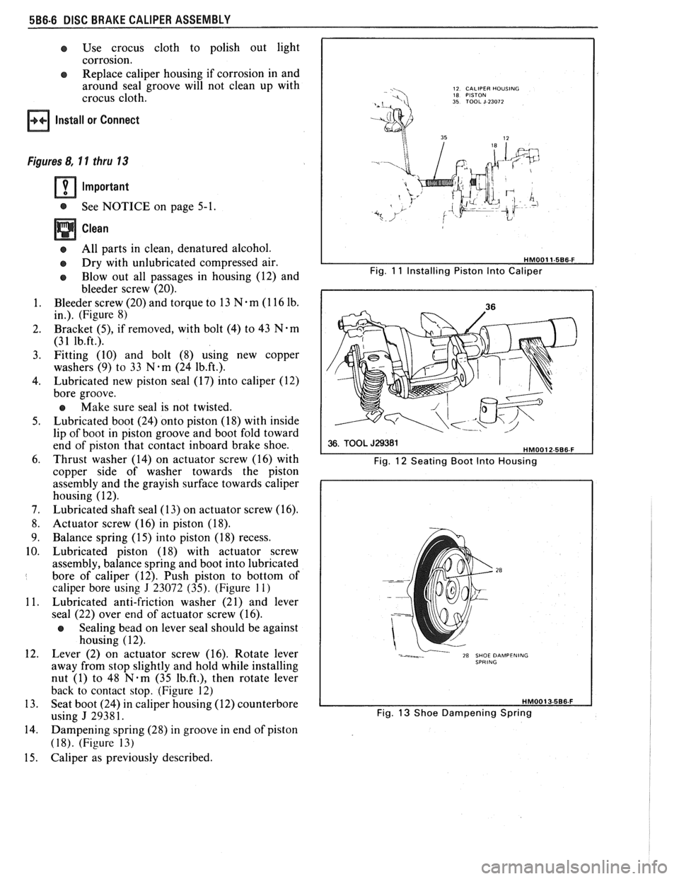
caliper bore using
J 23072 (35). (Figure 11)
Lubricated anti-friction washer (2 1) and lever
seal (22) over end of actuator screw (16).
a Sealing bead on lever seal should be against
housing
( 12).
Lever (2) on actuator screw (16). Rotate lever
away from stop slightly and hold while installing
nut (1) to 48
N-m (35 Ib.ft.), then rotate lever
back to contact stop. (Figure 12)
Seat boot (24) in caliper housing (12) counterbore
using
J 29381.
Dampening spring (28) in groove in end of piston
(1 8). (Figure 13)
Caliper as previously described.
12 CALIPER HOUSING
18 PISTON
35 TOOL J 23072
Fig. 11 Installing Piston lnto Caliper
Fig.
12 Seating Boot lnto Housing
Fig.
13 Shoe Dampening Spring
Page 334 of 1825
DIRECT TORQUE DRUM BRAKE ASSEMBLY 5C3-7
Install or Connect
See NOTICE on page 5- 1.
1. Position wheel cylinder assembly (28) and hold in
place with wooden block between cylinder and
axle flange.
2. New retainer (19) over wheel cylinder abutement
using a 1-
1/8 inch 12-point socket (32) and socket
extention (31) as shown in figure
6.
3. Inlet tube nut to 17 N-m (13 1b-ft).
4. Bleed wheel cylinder.
BACKING PLATE
Remove or Disconnect
1. Raise
car and suitably support, see Section OA.
2. Brake
components as previously described.
3. Axle shaft, see Section 4B.
4. Parking brake
cable from backing plate
5. Brake pipe from wheel cylinder
6. Backing plate bolts and nuts
7. Anchor
pin nut and anchor pin
Install or Connect
1. Backing plate to axle flange
2. Backing plate to axle flange nuts and bolts to 58
N.m (45 lbs. ft.)
3. Anchor
in and nut to 140 N.m ( 103 Ibs. ft.)
4. Brake
pipe to
wheel cylinder to 15 N.nl (I l Ibs.
ft.)
5. Parking brake cable to backing plate
6. Axle shaft, see section 48
7. Brake
components as previously described
8. Lower car.
9. Bleed brake hydraulic syatcm
10. Adjust brake asscnlbly and parking brakc
UNIT REPAIR
WHEEL
CYLINDER OVERHAUL
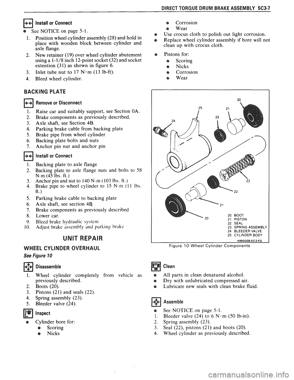
See Figure 10
+++ Disassemble [I]
1. Wheel cylinder completely from vehicle as
previously described.
2. Boots (20).
3. Pistons (21) and seals (22).
4. Spring assembly (23).
5. Bleeder valve (24).
e Cylinder bore for:
e Scoring
e Nicks
e Corrosion
e Wear
e Use crocus cloth to polish out light corrosion.
e Replace wheel cylinder assembly if bore will not
clean up with crocus cloth.
e Pistons for:
e Scoring
e Nicks
e Corrosion
e Wear
22 SEAL 23 SPRING ASSEMBLY 24 BLEEDER VALVE 25 CYLINDER BODY
Figure 10 Wheel Cylinder Components
Clean
e All parts in clean denatured alcohol.
e Dry with unlubricated compressed air.
e Lubricate new seals with clean brake fluid.
Assemble
e See NOTICE on page 5-1.
1. Bleeder valve (24) to 6 N.m (50 lb-in).
2. Spring assembly (23).
3. Seal
(22), pistons (21) and boots (20).
4. Wheel
cylinder as previously described,
Page 339 of 1825
![PONTIAC FIERO 1988 Service Repair Manual
6D2-4 POWER HEAD ASSEMBLY
STAKE
I STAKING TAB SOCKET WITH SCREWDRIVER
Figure 6 Staking Procedure
(Figures 7 thru 1 1)
(.+g Disassemble [I]
1.
Remove booster (35) and disconnect housings (9
PONTIAC FIERO 1988 Service Repair Manual
6D2-4 POWER HEAD ASSEMBLY
STAKE
I STAKING TAB SOCKET WITH SCREWDRIVER
Figure 6 Staking Procedure
(Figures 7 thru 1 1)
(.+g Disassemble [I]
1.
Remove booster (35) and disconnect housings (9](/manual-img/50/57415/w960_57415-338.png)
6D2-4 POWER HEAD ASSEMBLY
STAKE
I STAKING TAB SOCKET WITH SCREWDRIVER
Figure 6 Staking Procedure
(Figures 7 thru 1 1)
(.+g Disassemble [I]
1.
Remove booster (35) and disconnect housings (9
and 10) as previously described.
2. Piston rod
(12), reaction retainer (13) and power
head silencer (14).
3. Power piston assembly (41) along with pushrod
(32).
e Grasp assemby at outside edge of housing
divider (19) and diaphragms (16 and 20).
e Hold with pushrod (32) down against a
hard surface.
e Use a slight force or impact to dislodge
diaphragm retainer (15).
4. Primary diaphragm (16) and primary support
plate (17) from housing divider (19).
5. Primary diaphragm (16) from primary support
plate (17).
6. Secondary diaphragm (20) and secondary
support plate (21) from housing divider (19).
7. Secondary piston bearing (18) from housing
divider (19).
8. Secondary diaphragm (20) from secondary
support plate
(2 1).
e Parts for:
e Corrosion
e Nicks
e Cracks
e Cuts
e Scoring
e Distortion
e Excessive wear
e Use crocus cloth to polish away minor corrosion
to diaphragm supports, or housing divider.
@ All parts in clean denatured alcohol.
e Do not immerse power piston and pushrod
assembly in alcohol, rather wipe clean with an
alcohol dampened cloth.
e Dry with unlubricated compressed air.
Assemble
1. Lubricate inside diameter of secondary
diaphragm (20) lip, inside diameter of primary
diaphragm (16) lip and secondary piston bearing
(18) with a thin layer of silicone grease.
2. Secondary diaphragm (20) into secondary
support plate (21).
3. Secondary diaphragm (20) and support plate (21)
over power piston assembly (41) and
pushrod
(32). Use J 28458 as a guide to protect the power
piston.
4. Secondary piston bearing (18) into housing
divider (19) with flat surface of bearing on same
side as six raised lugs on divider.
5. Secondary piston bearing (18) and housing
divider (19) over power piston assembly (41) and
pushrod (32). Use J 28458 as a guide.
6. Primary diaphragm (16) into primary support
plate (17).
7. Fold primary diaphragm (16) up, away from
primary support plate (17).
8. Primary diaphragm (16) and support plate (17)
over power piston assembly (41) and
pushrod
(32).
9. Fold primary diaphragm (16) back into position
and pull diaphragm
OD over formed flange of
housing divider (19).
e Check that beads on secondary diaphragm
(20) are seated evenly around complete
circumference.
10. New diaphragm retainer (15) and seat using
J
28458 Retainer Installer.
11. Silencer
(14), reaction retainer (13) and piston
rod (12).
12. Reassemble booster as previously described.
POWER PISTON OVERHAUL
Tools Required:
J 29282 Air Valve Push Rod Retainer
Installer
(Figures 12 thru 14)
+++ Disassemble GI
1. Reaction body retainer (24).
2. Reaction body (25).
Page 347 of 1825
6-2 ENGINE GENERAL INFORMATION
6E3 - Fuel Injection (Ported) This section has information
on all exhaust
system parts, such as tailpipes, mufflers, and the
SECTION 6F - EXHAUST SYSTEM catalytic converter.
GENERAL INFORMAflION
CLEANLINESS AND CARE
An automobile engine is a combination of many
machined, honed, polished and lapped surfaces with
tolerances that are measured in the ten-thousandths of
an inch. When any internal engine parts are serviced,
care and cleanliness are important. A liberal coating of
engine oil should be applied to friction areas during
assembly, to protect and lubricate the surfaces on
initial operation. Throughout this section, it should be
understood that proper cleaning and protection of
machined surfaces and friction areas is part of the
repair procedure. This is considered standard shop
practice, even if not specifically stated. PREVENTING
DAMAGE AND IN
CONTRIBUTING TO RELIABLE ENGINE
PERFORMANCE.
When raising or supporting the engine for any
reason, do not use a jack under the oil pan. Due to the
small clearance between the oil pan and the oil pump
screen, jacking against the oil pan may cause it to be
bent against the pump screen resulting in a damaged
oil pick-up unit.
When working on the engine, remember that the
12-volt electrical system is capable of causing short
circuits. When performing any work where electrical terminals could possibly be grounded, the ground cable
of the battery should be disconnected at the battery.
Any time the carburetor or air cleaner is
train components are removed removed, the intake opening should be covered. This for service, they should be in order' will protect against entrance of foreign be installed in the same locations, and with the same material, which could follow the intake passage into mating surfaces, as when removed
the cylinder and cause extensive damage when the -
Battery cables should be disconnected before any engin; is started.
major work is performed on the engine. Failure to IN THE MECHANICAL PROCEDURES
disconnect cables may result in damage to wire harness DESCRIBED IN THIS SECTION, GENERALLY
or other electrical parts. NO
REFERENCES WILL BE MADE TO THE
REMOVAL OF OPTIONAL EQUIPMENT SUCH
ENGINE SERVICE AS POWER STEERING PUMP, AIR
CONDITIONING COMPRESSOR, ETC.
THE FOLLOWING INFORMATION ON SHOULD IT BECOME NECESSARY TO
ENGINE SERVICE SHOULD BE NOTED REMOVE ANY SUCH ITEM TO
PERFORM
CAREFULLY, AS IT IS IMPORTANT IN OTHER SERVICE, REFER TO THE
APPROPRIATE SECTION OF THIS SERVICE
MANUAL FOR SPECIFIC INFORMATION.
ENGINE PERFORMANCE DIAGNOSIS
INTRODUCTION interchangeably for so long, it was necessary to decide
on the most common usage and then define them. If the
Engine Performance procedures are definition is not understood, and the exact Symptom is
guides that will lead to the most probable causes of not used, the Diagnostic procedure will not work. engine performance complaints. They cover the
components of the fuel, ignition, and mechanical It
is important to keep two facts in mind:
systems that could cause a particular
complaint, and 1. The procedures are written to diagnose problems
then outline repairs in a logical sequence. on cars
that have
"run well at one time" and
that time and wear have created the condition.
It is important to determine if the
"Service ~~~i~~ soon- light is "ON,~' or has come for 2. All possible causes cannot be covered,
a short interval while driving. If the
"Service Engine particularly with regard to emission controls. If
Soon" light has come "ON," the Computer doing the work prescribed does not correct the
Command Control System or DECS should be complaint, then either the wrong Symptom was
checked for stored
"Trouble Codes" (See Diagnostic used, or a more detailed analysis will have to be
Circuit Check, Section 6E, for the engine you are made.
working on) which may indicate the cause for the All of the Symptoms can be caused by worn out
performance
complaint.Each Symptom is defined, and or defective parts such as Spark Plugs, Ignition
it is important that the correct one be selected, based Wiring, etc. If time and/or mileage indicate that
on the complaints reported or found. The definition of parts should be replaced, it is recommended that
each symptom is included with the symptom. it
be done.
The words used may not be what you are used to Refer to:
in all cases, but because these terms have been used
@ Section 6E - Driveability and Emissions
Page 349 of 1825
6-4 ENGINE GENERAL INFORMATION
Bent connecting rod.
HEAVY KNOCK H0"FVVI"F TORQUE APPLIED
Broken balancer, or pulley hub. Replace parts as e Exhaust system grounded. Reposition as
necessary. necessary.
Loose torque converter bolts. Flywheel
cracked.
e Excessive main bearing clearance. Replace as
Accessory belts too tight or nicked. Replace
necessary.
and/or tension to specs as necessary.
e Excessive rod bearing clearance. Replace as
necessary.
LIGHT KNOCK HOT
Detonation or spark knock. Check operation of e Loose torque converter bolts.
EST or ESC (See Section
6D or 6E). Check e Exhaust leak at manifold. Tighten bolts and/or
engine timing and fuel quality.
replace gasket.
8 Excessive rod bearing clearance. Replace
bearings as necessary.
KNOCKS ON INITIAL START-UP BUT ONLY LASTS A FEW SECONDS
Noisy mechanical fuel pump. Replace pump.
When the engine is stopped, some valves
will be open. Spring pressure against lifters
Improper oil viscosity. Install proper oil viscosity will
tend to bleed lifter down. Attempts to
for expected temperatures. See Owner's Manual. repair
should be made only if the problem
is consistent.
Hydraulic lifter bleed down. Clean, test and @ Excessive crankshaft end clearance. Replace
replace as necessary. crankshaft
thrust bearing.
@ Excessive front main bearing clearance. Replace
worn parts.
KNOCKS AT IDLE HOT
Loose or worn drive belts. Tension and/or @ Excessive piston pin clearance. Ream and install
replace as necessary. oversize pins. (VIN R and 2) or replace piston
A/C Compressor or generator bearing. Replace and
pin.
as necessary.
e Connecting rod alignment. Check and replace
rods as necessary.
Noisy mechanical fuel pump. Replace pump.
8 Insufficient piston to bore clearance. Hone bore
Valve train. Replace parts as necessary. and
fit new piston.
@ Loose crankshaft balancer. Torque and/or
Improper oil viscosity. Install proper viscosity oil
replace worn parts.
for expected temperature4 See Owner" e Piston pin offset to wrong side. Install correct
ENGINE OVERHEATS
Coolant system leak, oil cooler system leak, or
2. Belt slipping or damaged. Replace tensioner, or
coolant recovery system not operating. Check for belt, as required.
leaks and correct as required. Check coolant
3. Thermostat stuck closed. Check and replace if
recovery tank, hose and radiator cap.
required.
4. Electrical cooling fan operation. See the
ELECTRICAL TROUBLESHOOTING
MANUAL.
5. Head gasket leaking. Check and repair as
required.
Page 358 of 1825
2.8 LITER V-6 6A2-7
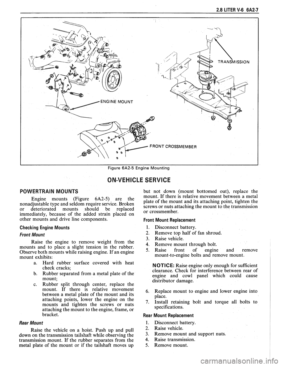
I I Figure 6A2-5 Engine Mounting
ON-VEHICLE SERVICE
POWERTRAIN MOUNTS but not down (mount bottomed out), replace the
mount. If there is relative movement between a metal
Engine mounts (Figure 6A2-5) are the plate of the mount and its attaching point, tighten the nonadjustable type and seldom require service. Broken screws or nuts attaching the mount to the transmission or deteriorated mounts should be replaced or cross member^
immediately, because of the added strain placed on
other mounts and drive line components.
Front Mount Replacement
Checking Engine Mounts
1. Disconnect battery.
Front Mount 2. Remove top half of fan shroud.
3. Raise vehicle.
Raise the engine to remove weight from the
4. Remove mount through bolt. mounts and to place a slight tension in the rubber.
Observe both mounts while raising engine. If an engine 5. Raise front of engine and remove
mount exhibits: mount-to-engine
bolts and remove mount.
l
a. Hard rubber surface covered with heat
check cracks;
b. Rubber separated from a metal plate
of the
mount;
c. Rubber split through center, replace the
mount. If there is relative movement
between a metal plate of the mount and its
attaching points, lower the engine on the
mounts and tighten the screws or nuts
attaching the mount to the engine, frame, or
bracket.
Rear Mount
Raise the vehicle on a hoist. Push up and pull
down on the transmission tailshaft while observing the
transmission mount. If the rubber separates from the
metal plate of the mount or if the tailshaft moves up
NOTICE: Raise engine only enough for sufficient
clearance. Check for interference between rear of
engine and cowl panel which could cause
distributor damage.
6. Replace mount to engine and lower engine into
place.
7. Install retaining bolt and torque all bolts to
specifications.
Rear Mount Replacement
1. Disconnect battery.
2. Raise vehicle.
3. Remove mount and support nuts.
4. Raise transmission.
5. Remove mount.
Page 362 of 1825
2.8 LITER V-6 8A2-11
ENGAGE AT
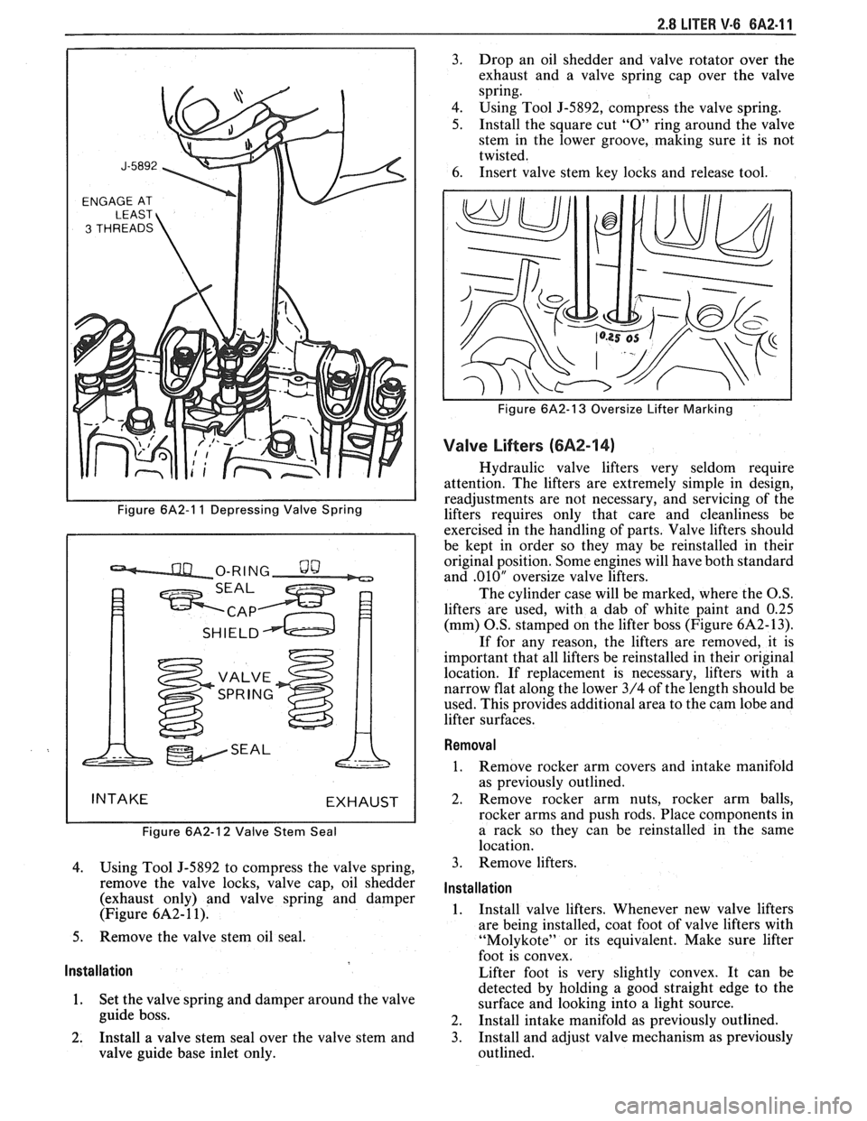
Figure 6A2-1 1 Depressing Valve Spring
Figure
6A2-12 Valve Stem Seal
4. Using Tool J-5892 to compress the valve spring,
remove the valve locks, valve cap, oil shedder
(exhaust only) and valve spring and damper
(Figure
6A2- 1 1).
5. Remove the valve stem oil seal.
Installation
1. Set the valve spring and damper around the valve
guide boss.
2. Install a valve stem seal over the valve stem and
valve guide base inlet only. 3.
Drop an oil shedder and valve rotator over the
exhaust and a valve spring cap over the valve
spring.
4. Using Tool
5-5892, compress the valve spring.
5. Install the square cut "0" ring around the valve
stem in the lower groove, making sure it is not
twisted.
6. Insert valve stem key locks and release tool.
Figure 6A2-13 Oversize Lifter Marking
Valve Lifters (6A2-14)
Hydraulic valve lifters very seldom require
attention. The lifters are extremely simple in design,
readjustments are not necessary, and servicing of the
lifters requires only that care and cleanliness be
exercised in the handling of parts. Valve lifters should
be kept in order so they may be reinstalled in their
original position. Some engines will have both standard
and
.010" oversize valve lifters.
The cylinder case will be marked, where the O.S.
lifters are used, with a dab of white paint and
0.25
(mm) O.S. stamped on the lifter boss (Figure 6A2- 13).
If for any reason, the lifters are removed, it is
important that all lifters be reinstalled in their original
location. If replacement is necessary, lifters with a
narrow flat along the lower 3/4 of the length should be
used. This provides additional area to the cam lobe and
lifter surfaces.
Removal
1. Remove rocker arm covers and intake manifold
as previously outlined.
2. Remove rocker arm nuts, rocker arm balls,
rocker arms and push rods. Place components in
a rack so they can be reinstalled in the same
location.
3. Remove lifters.
Installation
1. Install valve lifters. Whenever new valve lifters
are being installed, coat foot of valve lifters with
"Molykote" or its equivalent. Make sure lifter
foot is convex.
Lifter foot is very slightly convex. It can be
detected by holding a good straight edge to the
surface and looking into a light source.
2. Install intake manifold as previously outlined.
3. Install and adjust valve mechanism as previously
outlined.
Page 364 of 1825
2.8 LITER V.6 6A2.13
Torque bolts as shown in Figure 6A2-15.
4. Install
push rods and loosely retain with rocker
arms. Make sure lower ends of
pushrods are in
lifter seats.
5. Install intake manifold.
6. Raise vehicle.
7. Install dipstick tube bracket.
8. Connect exhaust pipe
to exhaust manifold flange.
9. Lower vehicle.
10. Adjust
valve lash as previously outlined.
11. Continue
following intake manifold installation
for build up.
Removal (Right)
Remove intake manifold as previously outlined.
Raise vehicle.
Disconnect exhaust pipe.
Drain engine block.
Lower vehicle.
Loosen rocker arms until able to remove push
rod.
Remove serpentine belt.
Remove tensioner.
Remove A.I.R. bracket.
Remove generator bracket.
Remove head bolts.
Remove head.
Installation (Right)
The gasket surfaces on both the head and cylinder
case
deck must be clean of any foreign matter and free
of nicks of heavy scratches. Cylinder bolt threads in the
case and threads on the cylinder head bolts must be
clean. Dirt will affect bolt torque.
1. Place the gasket in position, over the dowel pins,
with the note "This Side Up" showing.
2. Install cylinder head.
3. Coat cylinder head bolt threads with sealer,
#lo52080 or equivalent, and install bolts.
Torque bolts as shown in (Figure
6A2-15).
Install push rods and loosely retain with rocker
arms. Make sure lower ends of push rods are in
lifter seats.
Install intake manifold.
Raise vehicle.
Install exhaust pipe to exhaust manifold flange.
Lower vehicle.
Adjust valve lash as previously outlined.
Install AIR bracket.
Install tensioner.
Install generator bracket.
Continue following intake manifold installation
for build up.
Disassembly
1. With cylinder head removed, remove rocker arm
nuts, balls and rocker arms (if not previously
done).
2. Using tool J-8062, compress the valve springs and
remove valve keys. Release the compressor tool and
remove spring caps, oil shedders, springs and
damper assemblies, then remove oil seals.
3. Remove valves from cylinder head and place
them in a rack so they can be installed in their
original positions.
Cleaning and Inspection
Clean all carbon from combustion chambers and
valve ports using 'tool
5-8089.
Thoroughly clean valve guides using 5-8 10 1.
Clean all carbon and sludge from push rods,
rocker arms and push rod guides.
Clean valve stems and heads on a buffing wheel.
Clean carbon deposits from head gasket mating
surface.
Inspect cylinder head for cracks in the exhaust
ports, combustion chambers, or external cracks
to the water jacket.
Inspect the valves for burned heads, cracked faces
or damaged stems.
NOTICE: Excessive valve stem to bore clearance
will cause high oil consumption and may cause
valve breakage. Insufficient clearance will result in
noise and sticky functioning of the valve and
disturb engine smoothness.
8. Measure valve stem clearance as follows:
a. Clamp
a dial indicator on one side of the
cylinder head. Locate the indicator so that
movement of the valve stem from side to
side (crosswise to the head) will cause direct
movement of the indicator stem. The
indicator stem must contact the side of the
valve stem just above the guide.
b. Drop
the valve head
1.5mm off the valve
seat.
c. Move
the stem of the valve from side to side,
using light pressure, to obtain a clearance
reading. If clearance exceeds specifications,
it will be necessary to ream valve guides for
oversize valves. Service valves are available
in std., 089,
.394 and .775mm O.S. sizes.
9. Check
valve spring tension with tool J-8056,
spring tester. Springs should be compressed to the
specified height and checked against the
specifications chart. Springs should be replaced if
not within 44
N (10 Ibs.) of the specified load
(without dampers).
10. Inspect
rocker arm studs for wear or damage.
ROCKER ARM STUDS
Cylinder heads use threaded rocker arm studs.
Rocker arm studs that have damaged threads should
be replaced with new studs. If, for some reason, the
threads in the head
are damaged or stripped, the head
can be retapped, and a helical type insert added. If such
an insert is not available, the head should be replaced.
VALVE GUIDES
Valves with oversize stems are available in .089,
,394 and ,775mm over sizes. To ream the valve guide