1988 PONTIAC FIERO light
[x] Cancel search: lightPage 366 of 1825
2.8 LITER V.6 6A2-15
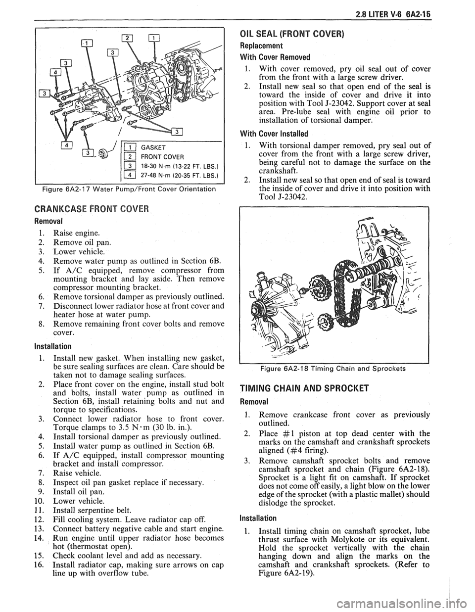
18-30 N.m (13-22 FT. LBS.)
I 11 47-48 N.m (20-35 FT. LBS.) I
Figure 6A2-17 Water Pump/Front Cover Orientation
CRANKCASE FRONT COVER
Removal
1. Raise engine.
2. Remove oil pan.
3. Lower vehicle.
4. Remove water pump as outlined in Section 6B.
5. If A/C equipped, remove compressor from
mounting bracket and lay aside. Then remove
compressor mounting bracket.
6. Remove torsional damper as previously outlined.
7. Disconnect lower radiator hose at front cover and
heater hose at water pump.
8. Remove remaining front cover bolts and remove
cover.
Installation
1. Install new gasket. When installing new gasket,
be sure sealing surfaces are clean. Care should be
taken not to damage sealing surfaces.
2. Place front cover on the engine, install stud bolt
and bolts, install water pump as outlined in
Section 6B, install retaining bolts and nut and
torque to specifications.
3. Connect lower radiator hose to front cover.
Torque clamps to
3.5 N-m (30 lb. in.).
4. Install torsional damper as previously outlined.
5. Install water pump as outlined in Section 6B.
6. If A/C equipped, install compressor mounting
bracket and install compressor.
7. Raise vehicle.
8. Inspect oil pan gasket replace if necessary.
9. Install oil pan.
10. Lower vehicle.
11. Install serpentine belt.
12. Fill cooling system. Leave radiator cap off.
13. Connect battery negative cable and start engine.
14. Run engine until upper radiator hose becomes
hot (thermostat open).
15. Check coolant level and add as necessary.
16. Install radiator cap, making sure arrows on cap
line up with overflow tube.
OIL SEAL (FRONT COVER)
Replacement
With Cover Removed
1. With cover removed, pry oil seal out of cover
from the front with a large screw driver.
2. Install new seal so that open end of the seal is
toward the inside of cover and drive it into
position with Tool
5-23042. Support cover at seal
area. Pre-lube seal with engine oil prior to
installation of torsional damper.
With Cover Installed
1. With torsional damper removed, pry seal out of
cover from the front with a large screw driver,
being careful not to damage the surface on the
crankshaft.
2. Install new seal so that open end of seal is toward
the inside of cover and drive it into position with
To01 5-23042.
Figure 6A2-18 Timing Chain and Sprockets
TIMING CHAIN AND SPROCKET
Removal
1. Remove crankcase front cover as previously
outlined.
2. Place #1 piston at top dead center with the
marks on the camshaft and crankshaft sprockets
aligned (#4 firing).
3. Remove camshaft sprocket bolts and remove
camshaft sprocket and chain (Figure
6A2- 18).
Sprocket is a light fit on camshaft.
If sprocket
does not come off easily, a light blow on the lower
edge of the sprocket (with a plastic mallet) should
dislodge the sprocket.
Installation
1. Install timing chain on camshaft sprocket, lube
thrust surface with Molykote or its equivalent.
Hold the sprocket vertically with the chain
hanging down and align the marks on the
camshaft and crankshaft sprockets. (Refer to
Figure
6A2- 19).
Page 370 of 1825
2.8 LITER V-6 6A2-19
4. Measure the crankpin for out-of-round or taper
with a micrometer. If not within specifications,
replace or recondition the crankshaft. If within
specifications and a new bearing is to be installed,
measure the maximum diameter of the crankpin,
to determine new bearing size required.
5. If within specifications, measure new or used
bearing clearance with Plastigage or its
equivalent.
NOTICE: If a bearing is being fitted to an
out-of-round crankpin, be sure to fit to the
maximum diameter of the crankpin. If the bearing
is fitted to the minimum diameter and the
crankpin is out-of-round .025mm interference
between the bearing and
crankpin will result in a
rapid bearing failure.
a.
Place a piece of gaging plastic the full width
of the
crankpin as contacted by the bearing
(parallel to the crankshaft).
b. Install
the bearing in the connecting rod and
cap.
c. Install
the rod cap and evenly torque nuts
to specifications. Do not turn the crankshaft
with gaging plastic installed.
d. Remove
the rod cap and using the scale on
the gaging plastic envelope, measure the
gaging plastic width at the widest point.
6. If
the clearance exceeds specifications, select a
new, correct size, bearing and remeasure the
clearance.
If clearance cannot be brought to within
specifications, the
crankpin will have to be
ground undersize. If the
crankpin is already
at maximum undersize, replace crankshaft.
7. Coat the
bearing surface with oil, install the rod
cap and torque nuts to 50
N-m (37 lb. ft.).
8. When all connecting rod bearings have been
installed tap each rod lightly (parallel to the
crankpin) to make sure they have clearance.
9. Measure all connecting rod side clearances (see
specifications) between the rod cap and
crankshaft throw (Figure 6A2-23).
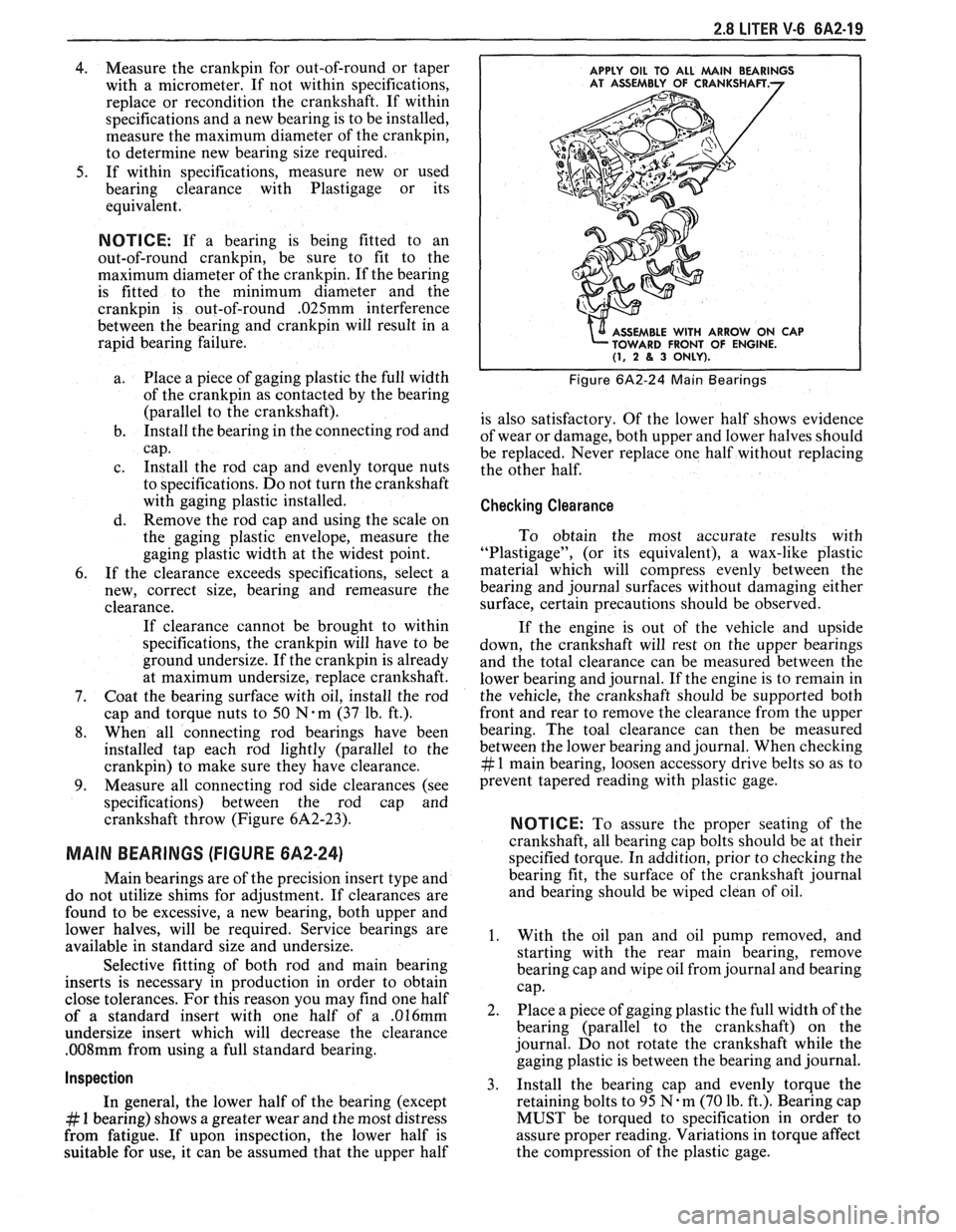
MAIN BEARINGS (FIGURE 6A2-24)
Main bearings are of the precision insert type and
do not utilize shims for adjustment. If clearances are
found to be excessive, a new bearing, both upper and
lower halves, will be required. Service bearings are
available in standard size and undersize.
Selective fitting of both rod and main bearing
inserts is necessary in production in order to obtain
close tolerances. For this reason you may find one half
of a standard insert with one half of a
.016mm
undersize insert which will decrease the clearance
.008mm from using a full standard bearing.
Inspection
In general, the lower half of the bearing (except
# 1 bearing) shows a greater wear and the most distress
from fatigue. If upon inspection, the lower half is
suitable for use, it can be assumed that the upper half
APPLY OIL TO ALL MAlN BEARINGS
E WITH ARROW ON CAP
FRONT OF ENGINE.
(1, 2 8, 3 ONLY).
Figure 6A2-24 Main Bearings
is also satisfactory. Of the lower half shows evidence
of wear or damage, both upper and lower halves should
be replaced. Never replace one half without replacing
the other half.
Checking Clearance
To obtain the most accurate results with
"Plastigage", (or its equivalent), a wax-like plastic
material which will compress evenly between the
bearing and journal surfaces without damaging either
surface, certain precautions should be observed.
If the engine is out of the vehicle and upside
down, the crankshaft will rest on the upper bearings
and the total clearance can be measured between the
lower bearing and journal. If the engine is to remain in
the vehicle, the crankshaft should be supported both
front and rear to remove the clearance from the upper
bearing. The toal clearance can then be measured
between the lower bearing and journal. When checking
# 1 main bearing, loosen accessory drive belts so as to
prevent tapered reading with plastic gage.
NOTICE: To assure the proper seating of the
crankshaft, all bearing cap bolts should be at their
specified torque. In addition, prior to checking the
bearing fit, the surface of the crankshaft journal
and bearing should be wiped clean of oil.
1. With the oil pan and oil pump removed, and
starting with the rear main bearing, remove
bearing cap and wipe oil from journal and bearing
cap.
2. Place a piece of gaging plastic the full width of the
bearing (parallel to the crankshaft) on the
journal. Do not rotate the crankshaft while the
gaging plastic is between the bearing and journal.
3. Install
the bearing cap and evenly torque the
retaining bolts to 95
N.m (70 lb. ft.). Bearing cap
MUST be torqued to specification in order to
assure proper reading. Variations in torque affect
the compression of the plastic gage.
Page 372 of 1825
2.8 LITER V-6 6A2-21
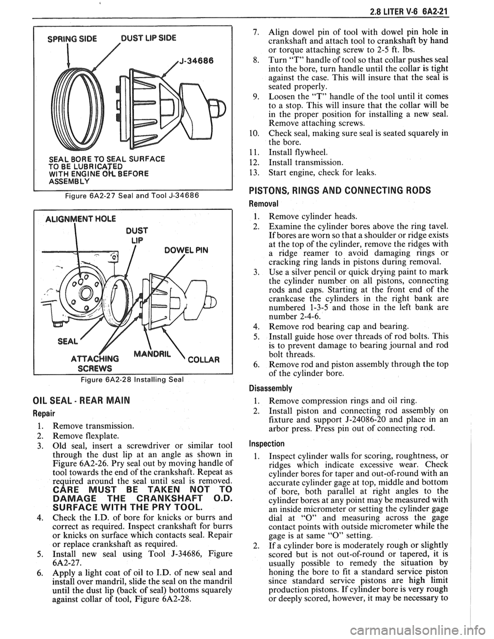
SEAL BORE TO SEAL SURFACE
TO BE LUBRICATED
WlTH ENGINE OK BEFORE I ASSEMBLY
Figure
6A2-27 Seal and Tool J-34686
ALIGNMENT HOLE
DUST
LIP
I SCREWS I
Figure 6A2-28 Installing Seal
OIL SEAL - REAR MAIN
Repair
1. Remove transmission.
2. Remove flexplate.
3. Old
seal, insert a screwdriver or similar tool
through the dust lip at an angle as shown in
Figure
6A2-26. Pry seal out by moving handle of
tool towards the end of the crankshaft. Repeat as
required around the seal until seal is removed.
CARE MUST BE TAKEN NOT TO
DAMAGE THE CRANKSHAFT O.D.
SURFACE
WlTH THE PRY TOOL.
4. Check
the I.D. of bore for knicks or burrs and
correct as required. Inspect crankshaft for burrs
or knicks on surface which contacts seal. Repair
or replace crankshaft as required.
5. Install new seal using Tool J-34686, Figure
6A2-27.
6. Apply a
light coat of oil to I.D. of new seal and
install over mandril, slide the seal on the mandril
until the dust lip (back of seal) bottoms squarely
against collar of tool, Figure
6A2-28.
7. Align dowel pin of tool with dowel pin hole in
crankshaft and attach tool to crankshaft by hand
or torque attaching screw to 2-5 ft. lbs.
8. Turn
"T" handle of tool so that collar pushes seal
into the bore, turn handle until the collar is tight
against the case. This will insure that the seal is
seated properly.
9. Loosen the "T" handle of the tool until it comes
to a stop. This will insure that the collar will be
in the proper position for installing a new seal.
Remove attaching screws.
10. Check seal,
making sure seal is seated squarely in
the bore.
1
1. Install flywheel.
12. Install transmission.
13. Start
engine, check for leaks.
PISTONS, RINGS AND CONNECTING RODS
Removal
1. Remove cylinder heads.
2. Examine the cylinder bores above the ring tavel.
If bores are worn so that a shoulder or ridge exists
at the top of the cylinder, remove the ridges with
a ridge reamer to avoid damaging rings or
cracking ring lands in pistons during removal.
3. Use a silver pencil or quick drying paint to mark
the cylinder number on all pistons, connecting
rods and caps. Starting at the front end of the
crankcase the cylinders in the right bank are
numbered 1-3-5 and those in the left bank are
number 2-4-6.
4. Remove rod bearing
cap and bearing.
5. Install
guide hose over threads of rod bolts. This
is to prevent damage to bearing journal and rod
bolt threads.
6. Remove rod
and piston assembly through the top
of the cylinder bore.
Disassembly
1. Remove compression rings
and oil ring.
2. Install piston and connecting rod assembly on
fixture and support J-24086-20 and place in an
arbor press. Press pin out of connecting rod.
Inspection
1. Inspect cylinder walls for scoring, roughtness, or
ridges which indicate excessive wear. Check
cylinder bores for taper and out-of-round with an
accurate cylinder gage at top, middle and bottom
of bore, both parallel at right angles to the
cylinder bores at any point may be measured with
an inside micrometer or setting the cylinder gage
dial at
"0" and measuring across the gage
contact points with outside micrometer while the
gage is at same
"0" setting.
2. If a cylinder bore is moderately rough or slightly
scored but is not out-of-round or tapered, it is
usually possible to remedy the situation by
honing the bore to fit a standard service piston
since standard service pistons are high limit
production pistons. If cylinder bore is very rough
or deeply scored, however, it may be necessary to
Page 373 of 1825
rebore the cylinder to fit an oversize piston in
order to insure satisfactory results.
3. If cylinder bore is tapered 0. lmm or more or is
out-of-round
O.lmm or more, it is advisable to
rebore for the smallest possible oversize piston
and rings. Below these limits, the cylinder bore
can be trued up with honing.
4. Clean carbon from piston surfaces and under side
of piston heads. Clean carbon from ring grooves
with suitable tool and remove any gum or varnish
from piston skirts with suitable solvent.
5. Carefully examine pistons for
rough or scored
surfaces; cracks in skirt or head; cracked or
broken ring lands; chipped or uneven wearing
pistons would cause rings to seat improperly or
have excessive clearance in ring grooves.
Damaged or faulty pistons should be replaced.
The pistons are cam ground, which means that
the diameter at a right angle to the wrist pin is
greater than the diameter parallel to the wrist pin.
When a piston is checked for size, it must be done
at points 90" to the piston pin. The piston should
be checked (for fitting purposes) in a plane
through the piston pin centerline.
6. Inspect surfaces of wrist pins and check for wear
by measuring worn or unworn surfaces with
micrometers. Occasionally pins will be found
tight due to gum or varnish deposits. This may be
corrected by removing the deposit with a suitable
solvent. If piston bosses are worn out-of-round or
oversize, the piston and pin assembly must be
replaced. Oversize pins are not practical due to
the pin being a press fit in the connecting rod.
Piston pins must fit the piston with an easy finger
push at 70°F (21°C)
(.0065 to .0091mm
clearance).
7. Examine all piston rings for scores, chips or
cracks. Check compression rings for tension by
comparing with new rings. Check gap of
compression rings by placing rings in bore at
bottom of ring travel. Measure gap with feeler
gage. Gap should be between
0.25mm and 0.
50mm. If gaps are excessive (over 0.50mm) it
indicates the rings have worn considerably and
should be replaced. Bore wear should be checked
before rings are replaced,
. l25mm bore wear will
result in
.39mm increase in ring gap.
Assembly
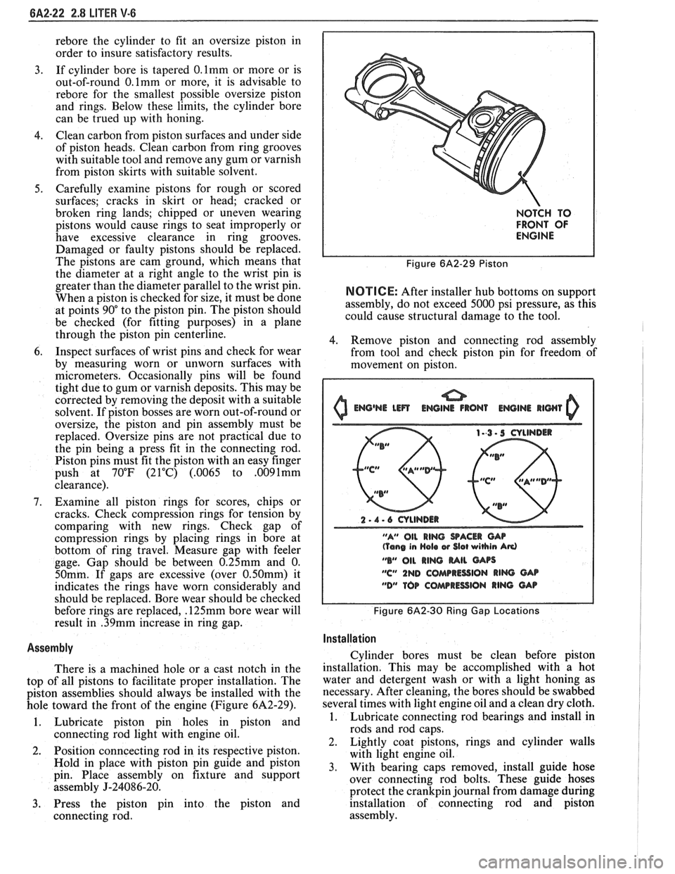
There is a machined hole or a cast notch in the
top of all pistons to facilitate proper installation. The
piston assemblies should always be installed with the
hole toward the front of the engine (Figure
6A2-29).
1. Lubricate piston pin holes in piston and
connecting rod light with engine oil.
2. Position
conncecting rod in its respective piston.
Hold in place with piston pin guide and piston
pin. Place assembly on fixture and support
assembly
J-24086-20.
3. Press the piston pin into the piston and
connecting rod.
NOTCH TO
FRONT OF
ENGINE
Figure 6A2-29 Piston
NOTICE: After installer hub bottoms on support
assembly, do not exceed 5000 psi pressure, as this
could cause structural damage to the tool.
4. Remove piston and connecting rod assembly
from tool and check piston pin for freedom of
movement on piston.
0 Emj@NE Lm ENGINE IRON1 EWINI llWl 0
2 - 1 - 6 CYLINDER
"A" OIL
RING SACER CAP (Tang in Hola w Slot wihin Ad
"B" 011 RING MIL GArs
"C" 1ND COMPRESSION RIM GAB
"DM TOP COAarRESSlON RING GAP
Figure 6A2-30 Ring Gap Locations I
I
Installation I
Cylinder bores must be clean before piston
installation. This may be accomplished with a hot
water and detergent wash or with a light honing as
necessary. After cleaning, the bores should be swabbed
several times with light engine oil and a clean dry cloth.
1. Lubricate connecting rod bearings and install in
rods and rod caps.
2. Lightly coat pistons, rings and cylinder walls
with light engine oil.
3. With bearing caps removed, install guide hose
over connecting rod bolts. These guide hoses
protect the
crankpin journal from damage during
installation of connecting rod and piston
assembly.
Page 374 of 1825
2.8 LITER V-6 8A2-23
4. Make sure the gap in the oil ring rails are in "up"
position toward center of engine and the gaps of
the compression rings are positioned as shown in
Figure
6A2-30.
5. Install each connecting rod and piston assembly
in its respective bore. Install with connecting rod
bearing tang slots on side opposite camshaft. Use
Tool J-8037 or J-8910 to compress the rings.
Guide the connecting rod into place on the
crankshaft journal.
Use a hammer handle and light blows to install
the piston into the bore. Hold the ring
compressor firmly against the cylinder block
until all piston rings have entered the cylinder
bore.
6. Install the bearing caps and torque nuts to
specifications. If bearing replacement is required
refer to "Connecting Rod Bearings".
Be sure to install new pistons in the same
cylinders for which they were fitted, and used
pistons in the same cylinder from which they
were removed. Each connecting rod and bearing
cap should be marked, beginning at the front of
the engine.
On V-6 engines, 1,3 and 5 are in the right bank
and 2,
4 and 6 are in the left bank. The numbers
on the connecting rod and bearing cap must be on
the same side when installed in the cylinder bore.
If a connecting rod is ever transposed from one
block or cylinder to another, new bearings should
be fitted and the connecting rod should be
numbered to correspond with the new cylinder
number.
NOTE. All dlrnenslons are In rn~ll~rnetres.
Figure 6A2-3 1 Service Pistons
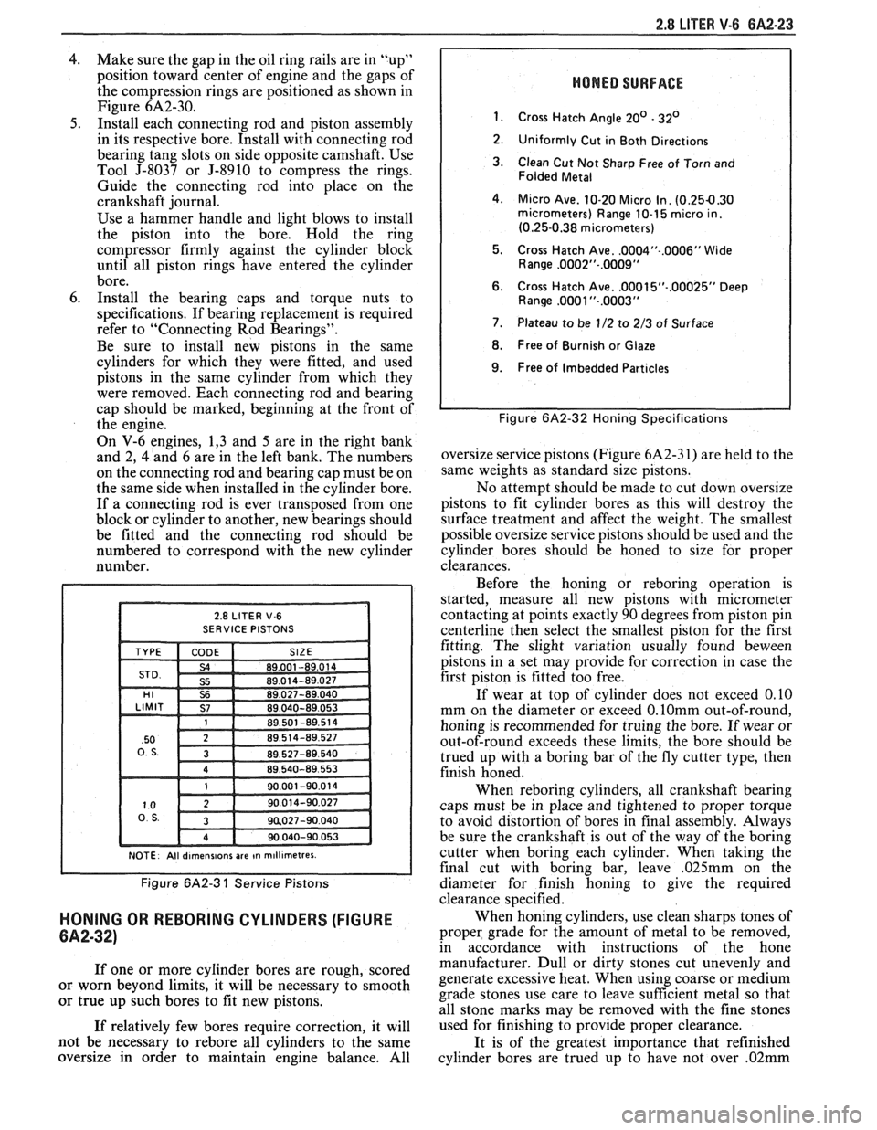
HONING OR REBORING CYLINDERS (FIGURE
6A2-32)
If one or more cylinder bores are rough, scored
or worn beyond limits, it will be necessary to smooth
or true up such bores to fit new pistons.
If relatively few bores require correction, it will
not be necessary to
rebore all cylinders to the same
oversize in order to maintain engine balance. All
HONED SURFACE
1.
Cross Hatch Angle 20' - 32'
2.
Uniformly Cut in Both Directions
3. Clean Cut Not Sharp Free of Torn and
Folded Metal
4. Micro Ave. 10-20 Micro In. (0.254.30 micrometers) Range 10-1 5 micro in.
(0.25-0.38 micrometers)
5. Cross Hatch Ave.
.0004"-.0006" Wide
Range ,0002"-.0009"
6. Cross Hatch Ave. ,0001 5"-.00025" Deep Ranw ,0081 "-.0003"
7. Plateau to be 1/2 to 2/3 of Surface
8. Free of Burnish or Glaze
I 9. Free of Imbedded Particles I
I I Figure 6A2-32 Honing Specifications
oversize service pistons (Figure 6A2-3 1) are held to the
same weights as standard size pistons.
No attempt should be made to cut down oversize
pistons to fit cylinder bores as this will destroy the
surface treatment and affect the weight. The smallest
possible oversize service pistons should be used and the
cylinder bores should be honed to size for proper
clearances.
Before the honing or
reboring operation is
started, measure all new pistons with micrometer
contacting at points exactly 90 degrees from piston pin
centerline then select the smallest piston for the first
fitting. The slight variation usually found
beween
pistons in a set may provide for correction in case the
first piston is fitted too free.
If wear at top of cylinder does not exceed 0.10
mm on the diameter or exceed
0.lOmm out-of-round,
honing is recommended for truing the bore. If wear or
out-of-round exceeds these limits, the bore should be
trued up with a boring bar of the fly cutter type, then
finish honed.
When
reboring cylinders, all crankshaft bearing
caps must be in place and tightened to proper torque
to avoid distortion of bores in final assembly. Always
be sure the crankshaft is out of the way of the boring
cutter when boring each cylinder. When taking the
final cut with boring bar, leave
,025mm on the
diameter for finish honing to give the required
clearance specified.
When honing cylinders, use clean sharps tones of
proper grade for the amount of metal to be removed,
in accordance with instructions of the hone
manufacturer. Dull or dirty stones cut unevenly and
generate excessive heat. When using coarse or medium
grade stones use care to leave sufficient metal so that
all stone marks may be removed with the fine stones
used for finishing to provide proper clearance.
It is of the greatest importance that refinished
cylinder bores are trued up to have not over
.02mm
Page 375 of 1825
6A2-24 2.8 LITER V-6
out-of-round or taper. Each bore must be final honed
to remove all stone or cutter marks and provide a
smooth surface. During final honing, each piston must
be fitted individually to the bore in which it will be
installed and should be marked to insure correct
installation.
After final honing and before the piston is
checked for fit, each cylinder bore must be thoroughly
washed to remove all traces of abrasives and then dried
thoroughly. The dry bore should then be brushed clean
with a power-driven fibre brush. If all traces of the
abrasives are not removed, rapid wear of new pistons
and rings will result.
FITTING PISTONS
1. Remove all rings
from pistons which will be
fitted. It is not necessary to separate rods from
pistons. If an excess amount of varnish or carbon
appears as a ridge at the top of the cylinder,
remove by scraping or sanding.
2. Wipe bores
and pistons clean, removing oil or
other foreign material. Select a piston-rod
assembly for the bore to be fitted (or piston and
pin if a new piston is being fitted) and position
down into the bore with the top of piston down.
The piston should fall free by its own weight
through the bore when when the bottom of the
piston skirt is 12 to 25mm from top of block.
Caution must be used to insure piston is not
damaged when it "falls" through the cylinder. If
it does not, the piston fit is too tight and another
piston should be selected until the piston will slide
freely through the bore without any force being
applied. Mark piston and bore for proper
assembly.
3. After a piston has been slected, which will slide
freely through a bore, it must be determined if
piston fit will be too loose. This is done by placing
a ,060 mm feeler gage for used pistons and a
.050
mm feeler gage for new pistons at least 150mm
long and not over 12mm wide, down into the
same bore with selected piston while holding
feeler to top of the bore.
Position selected piston and feeler down into the
bore until the bottom of the skirt is again 12 to
25 mm from top of block, being sure that the
feeler gage is
90" from the pin. If the piston hangs
on the feeler gage and does not fall free, it
indicates that the piston is correctly fitted to that
respective bore. Mark both piston and bore before
going to the next bore. If the piston fell free
during this check with the
.060mm feeler gage (.
050mm feeler gage for new pistons) then that
particular piston is too small for the bore and a
larger diameter piston will be required.
When checking more than one bore, it is very
possible that what may be a piston too small for one
bore will be a correct fit in another.
PISTON RINGS
When new piston rings are installed without
reboring cylinders, the glazed cylinder walls should be
slightly dulled, but without increasing the bore
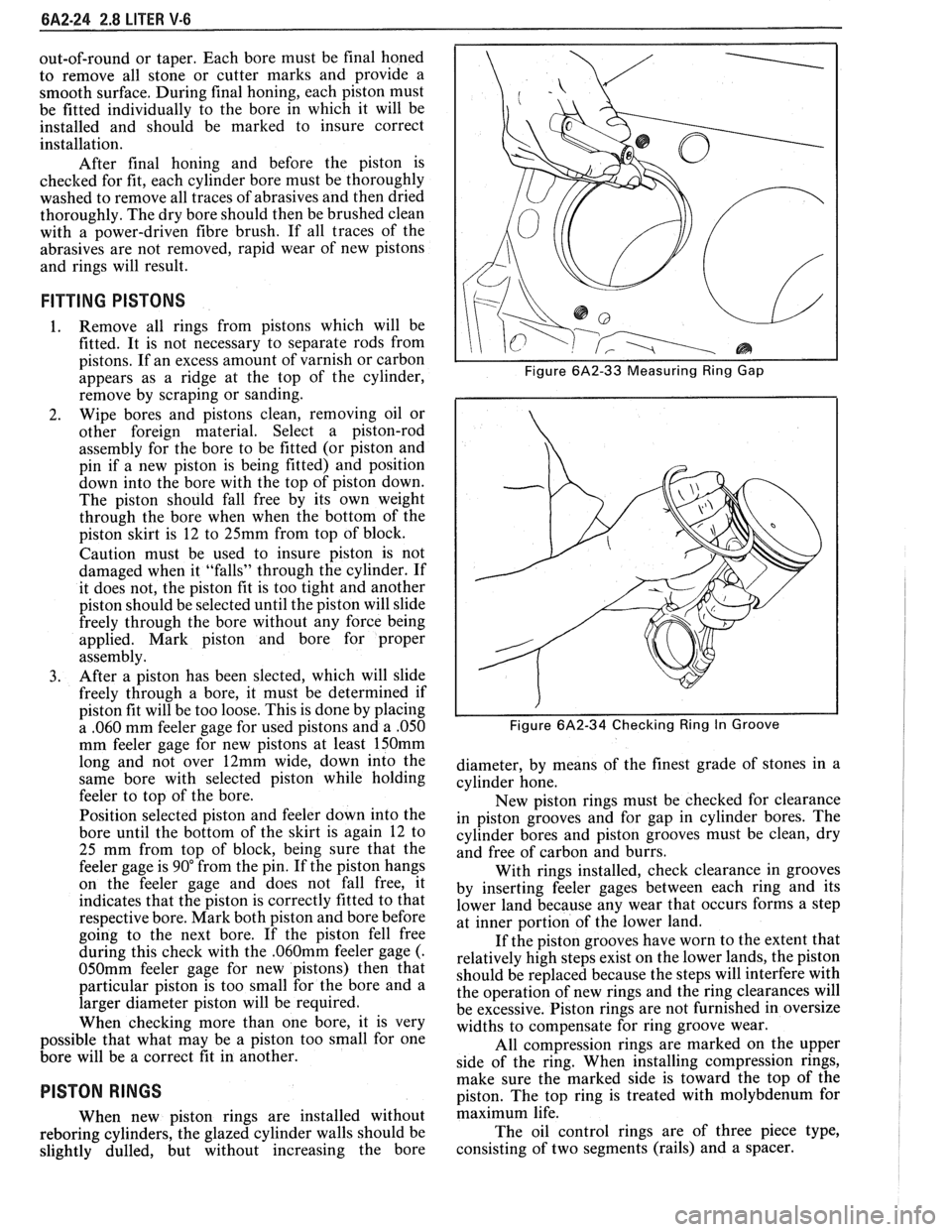
I I Figure 6A2-33 Measuring Ring Gap
i I
I I Figure 6A2-34 Checking Ring In Groove
diameter, by means of the finest grade of stones in a
cylinder hone.
New piston rings must be checked for clearance
in piston grooves and for gap in cylinder bores. The
cylinder bores and piston grooves must be clean, dry
and free of carbon and burrs.
With rings installed, check clearance in grooves
by inserting feeler gages between each ring and its
lower land because any wear that occurs forms a step
at inner portion of the lower land.
If the piston grooves have worn to the extent that
relatively high steps exist on the lower lands, the piston
should be replaced because the steps will interfere with
the operation of new rings and the ring clearances will
be excessive. Piston rings are not furnished in oversize
widths to compensate for ring groove wear.
All compression rings are marked on the upper
side of the ring. When installing compression rings,
make sure the marked side is toward the top of the
piston. The top ring is treated with molybdenum for
maximum life.
The oil control rings are of three piece type,
consisting of two segments (rails) and a spacer.
Page 384 of 1825
V-8 ENGINE BA3-5
ON-VEHICLE SERVICE
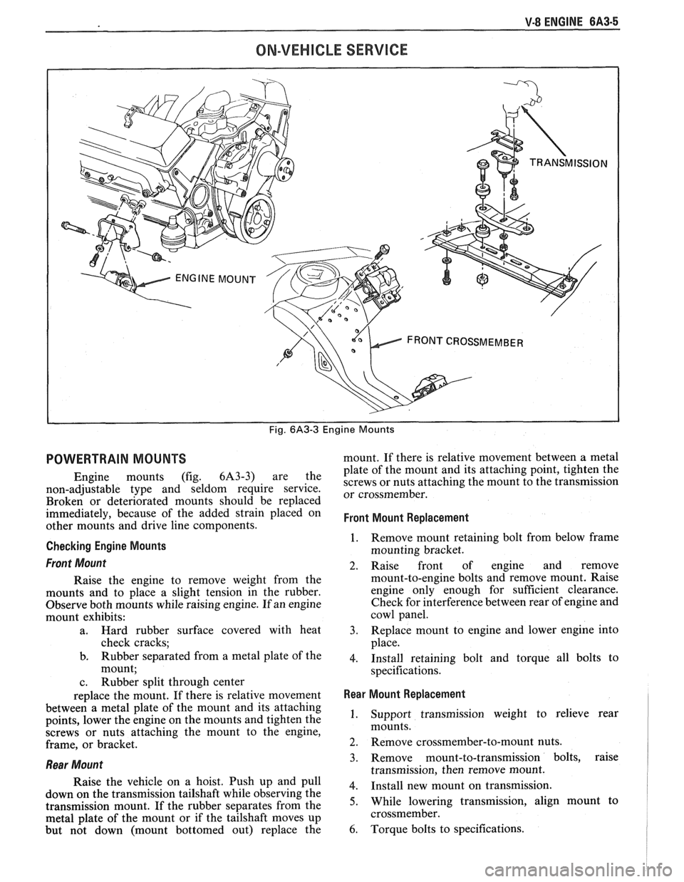
Fig. 6A3-3 Engine Mounts
POWERTRAIN MOUNTS
Engine mounts (fig. 6A3-3) are the
non-adjustable type and seldom require service.
Broken or deteriorated mounts should be replaced
immediately, because of the added strain placed on
other mounts and drive line components.
Checking Engine Mounts
Front Mount
Raise the engine to remove weight from the
mounts and to place a slight tension in the rubber.
Observe both mounts while raising engine. If an engine
mount exhibits:
a. Hard rubber surface covered with heat
check cracks;
b. Rubber separated from a metal plate of the
mount;
c. Rubber split through center
replace the mount. If there is relative movement
between a metal plate of the mount and its attaching
points, lower the engine on the mounts and tighten the
screws or nuts attaching the mount to the engine,
frame, or bracket.
Rear Mount
Raise the vehicle on a hoist. Push up and pull
down on the transmission tailshaft while observing the
transmission mount. If the rubber separates from the
metal plate of the mount or if the tailshaft moves up
but not down (mount bottomed out) replace the mount.
If there is relative movement between a metal
plate of the mount and its attaching point, tighten the
screws or nuts attaching the mount to the transmission
or crossmember.
Front Mount Replacement
1. Remove mount retaining bolt from below frame
mounting bracket.
2. Raise front of engine and remove
mount-to-engine bolts and remove mount. Raise
engine only enough for sufficient clearance.
Check for interference between rear of engine and
cowl panel.
3. Replace mount to engine and lower engine into
place.
4. Install retaining bolt and torque all bolts to
specifications.
Rear Mount Replacement I
1. Support transmission weight to relieve rear
mounts.
2. Remove crossmember-to-mount nuts.
3. Remove mount-to-transmission bolts, raise
transmission, then remove mount.
4. Install new mount on transmission.
5. While lowering transmission, align mount to
crossmember.
6. Torque bolts to specifications.
Page 389 of 1825
QA3-10 V-8 ENGINE
lnstallation
1. Install valve stem seal over valve stem and seat
against head.
2. Set
the valve spring and damper, oil shedder and
valve cap in place. Compress the spring with Tool
J-5892 and install oil seal in the lower groove of
the stem, making sure the seal is flat and not
twisted. A light coat of oil on the seal will help
prevent twisting.
3. Install
the valve locks and release the compressor
tool making sure the locks seat properly in the
upper groove of the valve stem. Grease may be
used to hold the locks in place while releasing the
compressor tool.
4. Using tool J-23994, apply vacuum to the valve
cap to make sure no air leaks past the seal.
5. Install spark plug and torque to 22 lb. ft.
(30N.m).
6. Install and adjust valve mechanism as previously
outlined.
VALVE LIFTERS
Hydraulic valve lifters very seldom require
attention. The lifters are extremely simple in design,
readjustments are not necessary, and servicing of the
lifters requires only that care and cleanliness be
exercised in the handling of parts.
Valve Lifter Diagnosis
1.
Momentarily Noisy When Car is Started:
This condition is normal. Oil drains from the
lifters which are holding the valves open when the
engine is not running. It will take a few seconds
for the lifter to fill after the engine is started.
2. Intermittently Noisy On Idle Only. Disappearing
When Engine Speed is Increased:
Intermittent clicking may be an indication of a
pitted check valve ball, or it may be caused by
dirt.
Correction: Clean the lifter and inspect. If check
valve ball is defective, replace lifter.
3. Noisy At Slow Idle Or With Hot Oil, Quiet With
Cold Oil Or As Engine Speed Is Increased:
High leak down rate. Replace suspect lifter.
4. Noisy At High Car Speeds And Quiet At Low
Speeds:
a. High oil level
- Oil level above the "Full"
mark allows crankshaft counterweights to
churn the oil into foam. When foam is
pumped into the lifters, they will become
noisy since a solid column of oil is required
for proper operation. Correction: Drain oil
inti1 proper level is obtained.
b. Low oil level - Oil level below the "Add"
mark allows the pump to pump air at high
speeds which results in noisy lifters.
Correction: Fill until proper oil level is
obtained.
c. Oil pan bent on bottom or pump screen
cocked or loose, replace or repair as
necessary. 5.
Noisy At Idle Becoming Louder As Engine Speed
Is Increased To 1500 rpm:
This noise is not connected with lifter
malfunction. It becomes most noticeable in the
car at 10 to 15 mph "1" (Low) range, or 30 to
35
mph "DM (Drive) range and is best described as
a
hashy sound. At slow idle, it may be entirely
gone or appear as a light ticking noise in one or
more valves. It is caused by one or more of the
following:
a. Badly worn or scuffed valve tip and rocker
arm pad.
b. Excessive valve stem to guide clearance.
c. Excessive valve seat
runout.
d. Off square valve spring.
e. Excessive valve face
runout.
f. Valve spring damper clicking on rotator.
Removal
1.
Remove intake manifold as previously outlined.
2. Remove valve mechanism as previously outlined.
3. Remove valve lifter retainer.
4. Remvoe valve lifter restrictor.
5. Remove valve lifters (Fig.
6A3-7). Place valve
lifters in a rack so that they may be reinstalled in
the same location.
Installation
1.
Coat roller of valve lifters with "Molykote" or its
equivalent and install valve lifters.
2. Install valve lifter restrictor.
3. Install valve lifter retainer.
4. Install intake manifold as previously outlined.
5. Install and adjust valve mechanism as outlined.
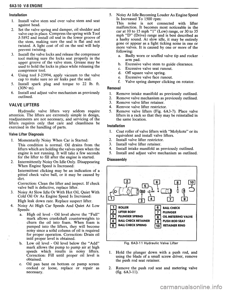
Disassembly
PLUNGER SPRING
Fig. 6A3-1 1 Hydraulic Valve Lifter
1. Hold the plunger down with a push rod, and
using the blade of a small screw driver, remove
the push rod seat retainer.
2. Remove the push rod seat and metering valve
(fig.
6A3- 1 1).