1988 PONTIAC FIERO light
[x] Cancel search: lightPage 291 of 1825
4B-18 REAR AXLE
tire wear patterns. One indication of this condition is
"swerving on acceleration." If swerving on
acceleration is encountered, check the rear wheels for
different tire size, air pressure, or excessively different
wear patterns, and tread depths, before proceeding into
an overhaul operation.
Checking Limited-Slip Operation
1. Place transmisison
in Park position.
2. Raise
rear of vehicle until wheels are off the
ground, remove one wheel and tire assembly.
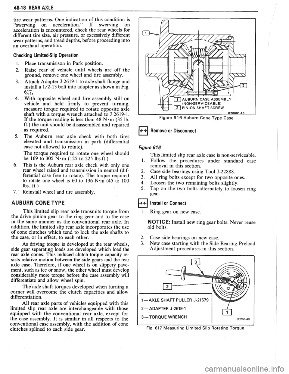
3. Attach Adapter J 2619-1 to axle shaft flange and
install a 1/2-13 bolt into adapter as shown in Fig.
617,
4. With opposite wheel and tire assembly still on
vehicle and held firmly to prevent turning,
measure torque required to rotate opposite axle
shaft with a torque wrench attached to J 2619-1.
If the torque reading is less than 48
N.m (35 lb.
ft.) the unit should be disassembled and repaired
as required.
5. The Auburn rear axle check with both tires
elevated and transmission in park (differential
case not allowed to rotate).
The torque required to rotate one wheel should
be 169 to 305
N-m (125 to 225 1bs.ft.).
6. This is the Auburn rear axle check with only one
rear wheel raised and transmission in neutral (dif-
ferential case free to rotate). The torque required
to rotate one wheel is
60 to 136 N-m (45 to 100
lbs. ft.)
7. Reinstall wheel and tire assembly.
AUBURN CONE TYPE
This limited slip rear axle transmits torque from
the drive pinion gear to the ring gear and to the case
in the same manner as the conventional rear axle. In
addition, the limited slip rear axle incorporates the use
of cone clutches which tend to lock the axle shafts to
the case, or in effect, to each other.
As driving torque is developed at the rear wheels,
side gear separating loads are developed which load the
rear axle cones. This induced clutch torque capacity re-
sists relative motion between the side gears and the rear
axle case. Therefore, if one wheel is on slippery pave-
ment, such as ice or snow, the other wheel must develop
considerably more torque before the case assembly will
differentiate and allow wheel spin.
The axle shaft torques developed when turning a
corner will overcome the clutch capacities and allow
differentiation.
All rear axle parts of vehicles equipped with this
limited slip rear axle are interchangeable with those
equipped with the conventional rear axle, except for
the case assembly. It is similar in all respects to the
conventional case assembly, with the addition of cone
clutches splined to each side gear.
INOWERVICEABLE) PINION SHAFT SCREW
Figure 6 16 Auburn Cone Type Case
Remove or Disconnect
Figure 6 16
This limited slip rear axle case is non-serviceable,
1. Follow the procedures under standard case
removal in this section.
2. Case side bearings using Tool J-22888.
3. All ring bolts except for two opposite ones.
4. Loosen the two remaining bolts slightly.
5. Tap on the two bolts alternately to loosen ring
gear.
Install or Connect
1.
Ring gear on new case.
NOTICE: Install new ring gear bolts. Never reuse
old bolts.
2. Case side bearings on new case.
3. New case starting with the Side Bearing Preload
Adjustment procedures in this section.
1 -AXLE SHAFT PULLER J-21579
2
-ADAPTER J-2619-1
3-TORQUE WRENCH
Fig.
617 Measuring Limited Slip Rotating Torque
Page 295 of 1825
5-2 BRAKES
GENERAL DESCRIPTION
COMPOSIE EASTER CYLINDER
This vehicle uses a composite master cylinder which has
an aluminum body and a clear nylon reservoir with fluid
level indicators. The master cylinder uses a "quick take-up" feature in the
rear chamber to reduce pedal travel which may result from
increased fluid displacement required to move the caliper
piston. The quick take-up master cylinder includes a spring
loaded ball check valve which holds pressure in the
large-
diameter rear chamber. When the brake is first applied, the
movement of the rear piston causes fluid to be displaced
forward, past the primary piston primary seal and into the
primary high pressure chamber, which feeds the front
brakes. At a predetermined pressure, 480-690
kPa (70-100
mi), the ball unseats and fluid from the largi! rear bore is
disblaced past the ball and into the reservoir. The primary
and secondary high pressure chambers supply pressure to
the front and rear brakes, respectively, in the usual way.
When the pedal is released, the large-bore chamber is filled
with fluid by drawing fluid from the reservoir around the
quick take-up lip seal, and also through a small orifice in the
ball seat.
BRAKE FLUID LEVEL INDICATOR
(Figure 1)
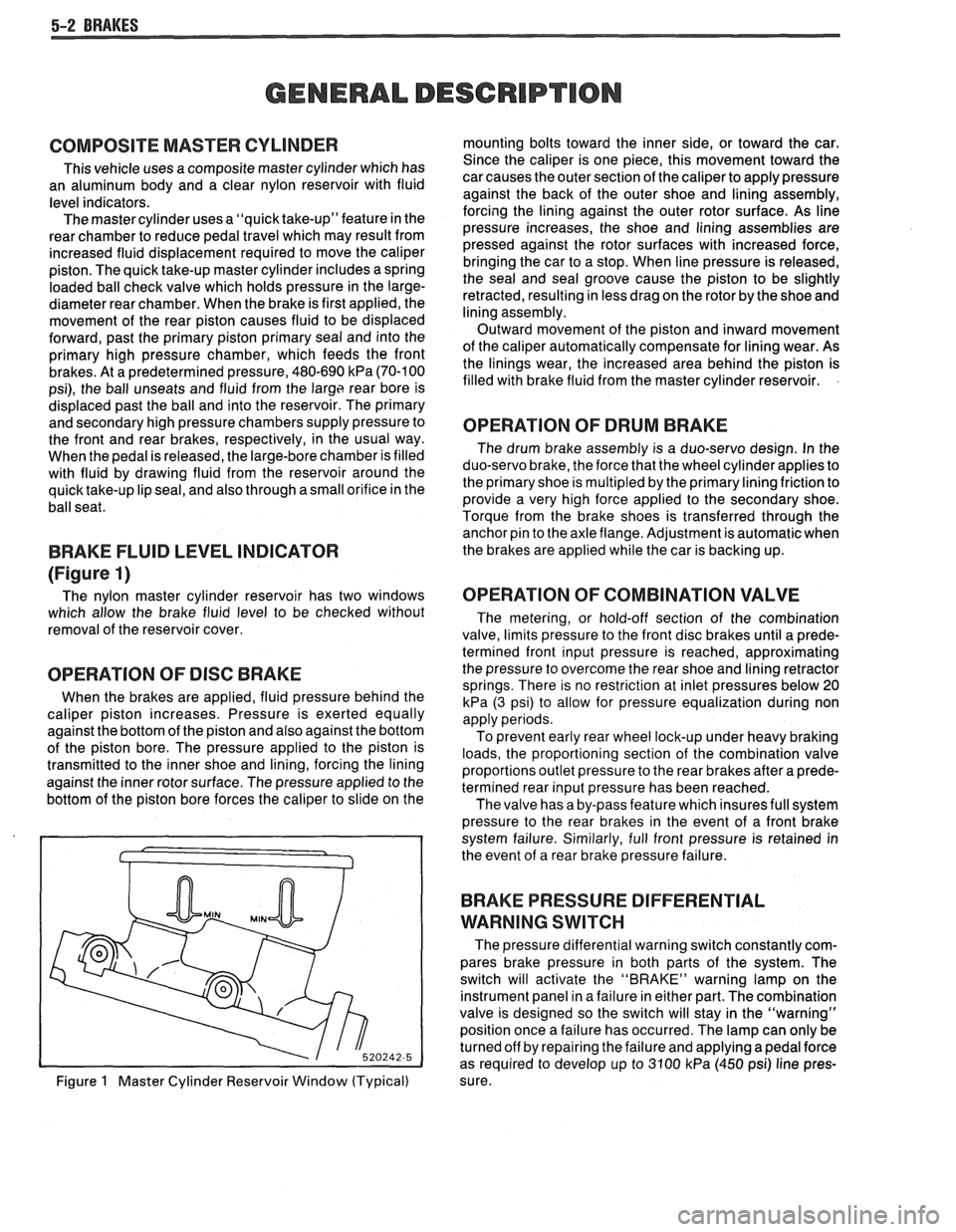
The nylon master cylinder reservoir has two windows
which allow the brake fluid level to be checked without
removal of the reservoir cover.
OPERATION OF DISC BRAKE
When the brakes are applied, fluid pressure behind the
caliper piston increases. Pressure is exerted equally
against the bottom of the piston and also against the bottom
of the piston bore. The pressure applied to the piston is
transmitted to the inner shoe and lining, forcing the lining
against the inner rotor surface. The pressure applied to the
bottom of the piston bore forces the caliper to slide on the
Figure
1 Master Cylinder Reservoir Window (Typical) mounting bolts toward the inner side,
or toward the car.
Since the caliper is one piece, this movement toward the
car causes the outer section of the caliper to apply pressure
against the back of the outer shoe and lining assembly,
forcing the lining against the outer rotor surface. As line
pressure increases, the shoe and lining assemblies are
pressed against the rotor surfaces with increased force,
bringing the car to a stop. When line pressure is released,
the seal and seal groove cause the piston to be slightly
retracted, resulting in less drag on the rotor by the shoe and
lining assembly.
Outward movement of the piston and inward movement
of the caliper automatically compensate for lining wear. As
the linings wear, the increased area behind the piston is
filled with brake fluid from the master cylinder reservoir.
OPERATION OF DRUM BRAKE
The drum brake assembly is a duo-servo design. In the
duo-servo brake, the force that the wheel cylinder applies to
the primary shoe is
multipled by the primary lining friction to
provide a very high force applied to the secondary shoe.
Torque from the brake shoes is transferred through the anchor pin to the axle flange. Adjustment is automatic when
the brakes are applied while the car is backing up.
OPERATION OF COMBINATION VALVE
The metering, or hold-off section of the combination
valve, limits pressure to the front disc brakes until a prede-
termined front input pressure is reached, approximating
the pressure to overcome the rear shoe and lining retractor
springs. There is no restriction at inlet pressures below 20
kPa (3 psi) to allow for pressure equalization during non
apply periods.
To prevent early rear wheel lock-up under heavy braking
loads, the proportioning section of the combination valve
proportions outlet pressure to the rear brakes after a prede-
termined rear input pressure has been reached.
The valve has a by-pass feature which insures full system
pressure to the rear brakes in the event of a front brake
system failure. Similarly, full front pressure is retained in
the event of a rear brake pressure failure.
BRAKE PRESSURE DIFFERENTIAL
WARNING
SWITCH
The pressure differential warning switch constantly com-
pares brake pressure in both parts of the system. The
switch will activate the "BRAKE" warning lamp on the
instrument panel in a failure in either part. The combination
valve is designed so the switch will stay in the "warning"
position once a failure has occurred. The lamp can only be
turned off by repairing the failure and applying a pedal force
as required to develop up to 3100
kPa (450 psi) line pres-
sure.
Page 296 of 1825
BRAKES 5-3
DIAGNOSIS AND INSPECTION
BRAKE SYSTEM TESTING
(Figures
2 through 4)
Brakes should be tested on dry, clean, reasonably
smooth and level roadway. A true test of brake performance
cannot be made if the roadway is wet, greasy or covered
with loose dirt so that all tires do not grip the road equally.
Testing will also be affected if the roadway is crowned
which would throw the weight of the car toward the wheels
on one side. If the roadway is too rough, the wheels will tend
to bounce. Test brakes at different car speeds with both light and
heavy pedal pressure, avoid locking the brakes and sliding
the tires. Locked brakes and sliding tires do not indicate
brake efficiency, because heavily braked, but turning
wheels will stop the car in less distance than locked brakes.
More tire-to-road friction is present with a heavily braked
turning tire than with a sliding tire. The brake system is designed and balanced to avoid
locking the wheels, except at very high deceleration levels.
The shortest stopping distance and best control is achieved
without brake lock-up.
Because of high deceleration capability, a firmer pedal
may be felt at higher deceleration levels.
External Conditions That Affect Brake Performance
1. Tires. Tires having unequal contact and grip on road
will cause unequal braking. Tires must be equally
inflated and tread pattern of right and left tires must
be approximately equal.
2. Car Loading. A heavily loaded car requires more
braking effort. When a car has unequal loading, the
most heavily loaded wheels require more braking
power than others.
3. Wheel Alignment. Misalignment of the wheels, par-
ticularly excessive camber and caster, will cause the
brakes to pull to one side.
4. Front Wheel Bearings. A loose front wheel bearing
BRAKE FLUID LEAKS
With engine running at idle and the transmission in neu-
tral, depress the brake pedal and hold a constant foot pres-
sure.
If the pedal gradually falls away with the constant
pressure, the hydraulic system may be leaking. Perform a
visual check to confirm any suspected leak.
Check the master cylinder fluid levels. While a slight drop
in reservoir level does result from normal lining wear, an
abnormally low level in either reservoir indicates
a leak in
the system. The hydraulic system may be leaking either
internally or externally. See "Master Cylinder Check."
Also, the system may appear to pass this test but still have
slight leakage.
If fluid levels are normal, check the vacuum booster
pushrod length. If an incorrect length pushrod is found,
adjust or replace the
pushrod. Check the service brake
pedal travel and the parking brake adjustment.
When checking the fluid levels, the master cylinder reser-
voir may be as low as
25 mm (1 inch) from the top if the front
linings are worn. This is not abnormal.
MASTER CYLINDER CHECK
These checks will help locate some master cylinder mal-
functions. Use the Brake Diagnosis Charts to help isolate
the problem if it is not found by using these tests.
1. Check for a cracked master cylinder casting or brake
fluid around the master cylinder. Leaks are indicated
only if there is at least a drop of fluid. A damp condi-
tion is not abnormal.
2. Check for a binding pedal linkage.
3. Disassemble the master cylinder and check for swol-
len or stretched piston
seal(s). If swollen seals are
found, substandard or contaminated brake fluid
should be suspected.
If contaminated, all compo-
nents should be disassembled and cleaned. All rub-
ber components should be replaced and all the pipes
should be flushed.
permits the front wheel to tilt and lose contact with the
SUBSTANDARD OR CONTAMINATED brake shoe linings causing erratic brake operation. BRAKE FLUID
WARNING LAMP OPERATION
The brake system uses a single red "BRAKE" warning
lamp located in the instrument panel cluster. When the
ignition switch is in the "START" position, the "BRAKE"
warning lamp should come on. It should go off when the
ignition switch returns to the "RUN" position.
The following conditions will activate the "BRAKE"
warning lamp:
1. Parking brake applied. The lamp should be on when
tfie parking brake is applied and the ignition switch is
"ON."
2. Pressure differential switch detects a failure. See
"Brake Pressure Differential Warning Switch" in this
section. Improper
brake fluid, mineral oil or water in the fluid may
cause the brake fluid to boil or the rubber components to
deteriorate.
If piston cups are swollen, the rubber parts have dete-
riorated. This deterioration may also be seen by swollen
wheel cylinder piston cups on the drum brake wheels or a
swollen master cylinder cover diaphragm.
If rubber deterioration is evident, disassemble all hydrau-
lic parts and wash with alcohol. Dry these parts with com-
pressed air before assembly to keep alcohol out of the
system. Replace all rubber parts in the system, including
hoses. Check for fluid on the linings. If excessive fluid is
found, replace the linings.
If master cylinder piston seals are satisfactory, check for
leakage or excessive heat conditions. If condition is not
found, drain fluid, flush with brake fluid, fill and bleed the
system.
Page 302 of 1825
BRAKES 5-9
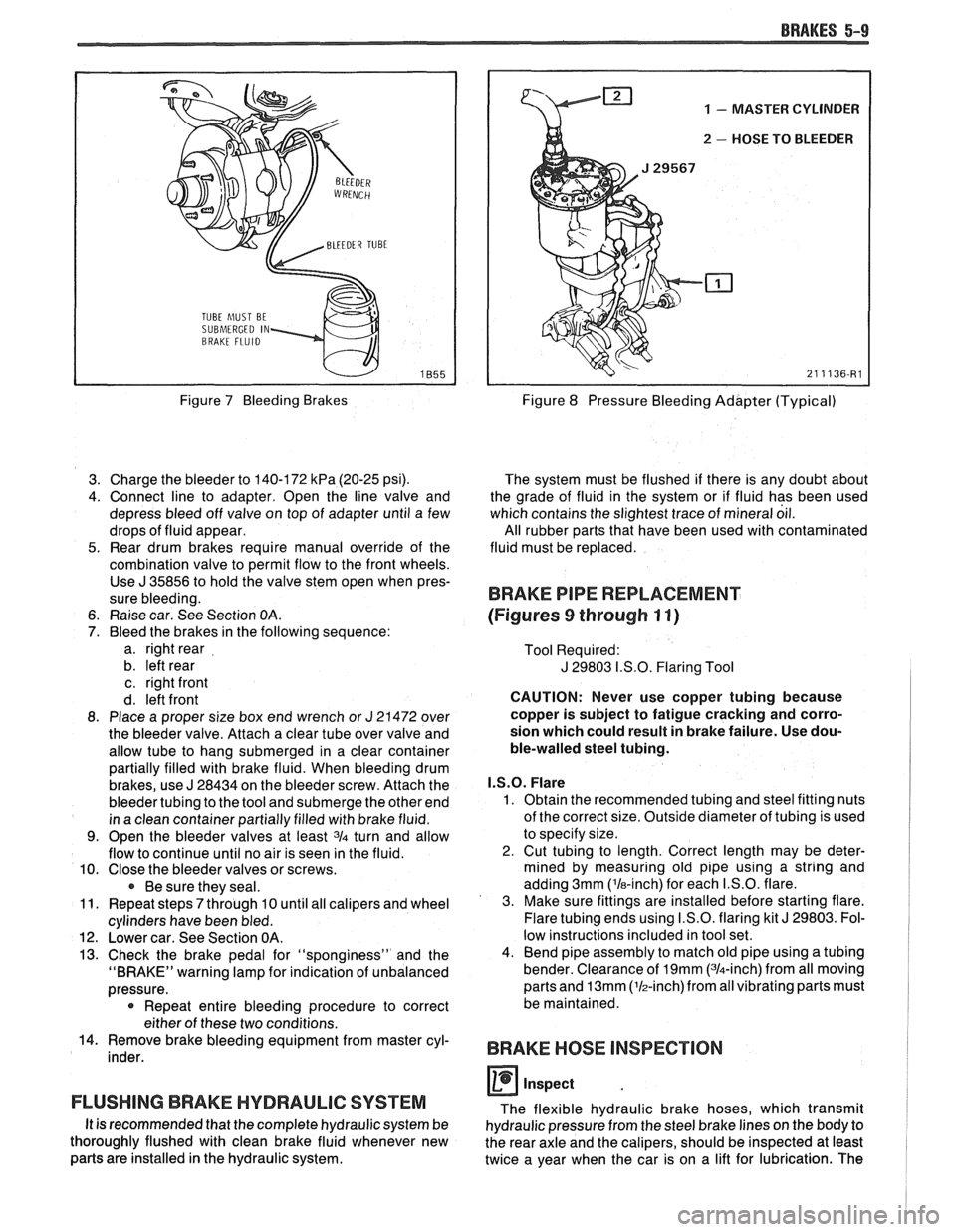
TUBE hlUST BE
SUBMERGED IN
Figure 7 Bleeding Brakes
3. Charge the bleeder to 140-172
kPa (20-25 psi).
4. Connect line to adapter. Open the line valve and
depress bleed off valve on top of adapter until a few
drops of fluid appear.
5. Rear drum brakes require manual override of the
combination valve to permit flow to the front wheels. Use
J 35856 to hold the valve stem open when pres-
sure bleeding.
6. Raise car. See Section
OA.
7. Bleed the brakes in the following sequence:
a. right rear
b. left rear
c. right front
d. left front
8. Place a proper size box end wrench or
J 21472 over
the bleeder valve. Attach a clear tube over valve and
allow tube to hang submerged in a clear container
partially filled with brake fluid. When bleeding drum
brakes, use
J 28434 on the bleeder screw. Attach the
bleeder tubing to the tool and submerge the other end
in a clean container partially filled with brake fluid.
9. Open the bleeder valves at least 3/4 turn and allow
flow to continue until no air is seen in the fluid.
10. Close the bleeder valves or screws.
Be sure they seal.
11. Repeat steps
7 through 10 until all calipers and wheel
cylinders have been bled.
12. Lower car. See Section OA.
13. Check the brake pedal for "sponginess" and the
"BRAKE" warning lamp for indication of unbalanced
pressure.
* Repeat entire bleeding procedure to correct
either of these two conditions.
14. Remove brake bleeding equipment from master cyl-
inder.
FLUSHING BRAKE HYDRAULIC SYSTEM
It is recommended that the complete hydraulic system be
thoroughly flushed with clean brake fluid whenever new
parts are installed in the hydraulic system.
1 - MASTER CYLINDER
u 2 - HOSE TO BLEEDER
Figure 8 Pressure Bleeding Adapter (Typical)
The system must be flushed if there is any doubt about
the grade of fluid in the system or if fluid has been used
which contains the slightest trace of mineral oil.
All rubber parts that have been used with contaminated
fluid must be replaced.
BRAKE PIPE REPLACEMENT
(Figures
9 through 11)
Tool Required:
J 29803 I.S.O. Flaring Tool
CAUTION: Never use copper tubing because
copper is subject to fatigue cracking and corro-
sion which could result in brake failure. Use dou-
ble-walled steel tubing.
I.S.O. Flare
1. Obtain the recommended tubing and steel fitting nuts
of the correct size. Outside diameter of tubing is used
to specify size.
2. Cut tubing to length. Correct length may be deter-
mined by measuring old pipe using a string and
adding 3mm ('la-inch) for each I.S.O. flare.
3. Make sure fittings are installed before starting flare.
Flare tubing ends using I.S.O. flaring kit
J 29803. Fol-
low instructions included in tool set.
4. Bend pipe assembly to match old pipe using a tubing
bender. Clearance of
19mm (314-inch) from all moving
parts and
13mm (lh-inch)from all vibrating parts must
be maintained.
BRAKE HOSE INSPECTION
0 inspect
The flexible hydraulic brake hoses, which transmit
hydraulic pressure from the steel brake lines on the body to
the rear axle and the calipers, should be inspected at least
twice a year when the car is on a lift for lubrication. The
Page 304 of 1825
BRAKES 5-11
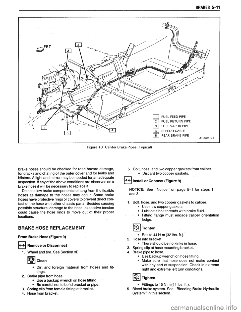
Figure 10 Center Brake Pipes (Typical)
brake hoses should be checked for road hazard damage,
for cracks and chafing of the outer cover and for leaks and
blisters.
A light and mirror may be needed for an adequate
inspection.
If any of the above conditions are observed on a
brake hose it will be necessary to replace it.
Do not allow brake components to hang from the flexible
hoses as damage to the hoses may occur. Some brake
hoses have protective rings or covers to prevent direct con-
tact of the hose with other chassis parts. Besides causing
possible structural damage to the hose, excessive tension
could cause the hose rings to move out of their proper
locations.
BRAKE HOSE REPLACEMENT
Front Brake Hose (Figure 9)
Remove or Disconnect
1. Wheel and tire. See Section 3E.
Clean
* Dirt and foreign material from hoses and fit-
tings.
2. Brake pipe from hose. 0 Use a backup wrench on hose fitting.
* Be careful not to bend bracket or pipe.
3. Spring clip from female fitting at bracket.
4. Hose from bracket.
5. Bolt, hose, and two copper gaskets from caliper.
* Discard two copper gaskets.
Install or Connect (Figure 9)
NOTICE: See "Notice" on page 5-1 for steps 1
and 3.
1. Bolt, hose, and two copper gaskets to caliper.
0 Use new copper gaskets.
Lubricate bolt threads with brake fluid.
0 Fitting flange must engage caliper orientation
ledge.
Tighten
0 Bolt to 44 N.m (32 Ibs. ft.).
2. Hose into bracket.
There should be no kinks in hose.
3. Spring clip at hose mounting bracket.
4. Brake pipe to hose. 0 Use backup wrench on hose fitting.
0 Make sure that hose does not make contact
with any part of suspension. Check in extreme
right and extreme left turn conditions.
* Fittings to 15 N.m (1 1 Ibs. ft.).
5. Bleed brake system. See "Bleeding Brake Hydraulic
System" in this section.
Page 309 of 1825
5-16 BRAKES
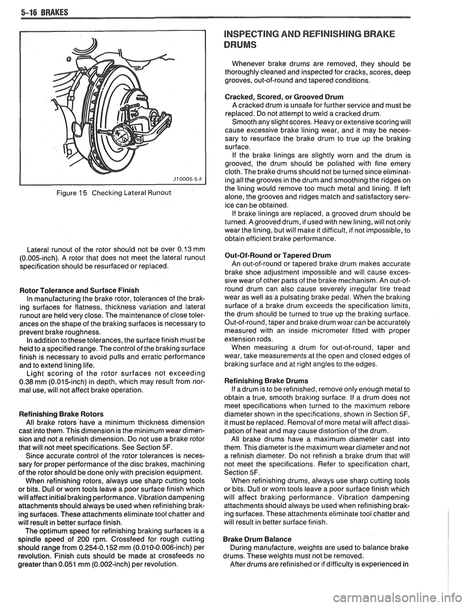
Figure 15 Checking Lateral Runout
Lateral runout of the rotor should not be over 0.13 mm
(0.005-inch). A rotor that does not meet the lateral runout
specification should be resurfaced or replaced.
Rotor Tolerance and Surface Finish
In manufacturing the brake rotor, tolerances of the brak-
ing surfaces for flatness, thickness variation and lateral
runout are held very close. The maintenance of close toler-
ances on the shape of the braking surfaces is necessary to
prevent brake roughness. In addition to these tolerances, the surface finish must be
held to a specified range. The control of the braking surface
finish is necessary to avoid pulls and erratic performance
and to extend lining life.
Light scoring of the rotor surfaces not exceeding
0.38
mrn (0.015-inch) in depth, which may result from nor-
mal use, will not affect brake operation.
Refinishing Brake Rotors
All brake rotors have a minimum thickness dimension
cast into them. This dimension is the minimum wear dimen-
sion and not a refinish dimension. Do not use a brake rotor
that will not meet specifications. See Section
5F.
Since accurate control of the rotor tolerances is neces-
sary for proper performance of the disc brakes, machining
of the rotor should be done only with precision equipment.
When refinishing rotors, always use sharp cutting tools
or bits. Dull or worn tools leave a poor surface finish which
will affect initial braking performance. Vibration dampening
attachments should always be used when refinishing brak-
ing surfaces. These attachments eliminate tool chatter and
will result in better surface finish.
The optimum speed for refinishing braking surfaces is a
spindle speed of 200 rpm. Crossfeed for rough cutting
should range from 0.254-0.152 mm (0.010-0.006-inch) per
revolution. Finish cuts should be made at crossfeeds no
greater than 0.051 mm (0.002-inch) per revolution.
INSPECTING AND REFlNlSHlMG BRAKE
DRUMS
Whenever brake drums are removed, they should be
thoroughly cleaned and inspected for cracks, scores, deep
grooves, out-of-round and tapered conditions.
Cracked, Scored, or Grooved Drum
A cracked drum is unsafe for further service and must be
replaced. Do not attempt to weld a cracked drum.
Smooth any slight scores. Heavy or extensive scoring will
cause excessive brake lining wear, and it may be neces-
sary to resurface the brake drum to true up the braking
surface.
If the brake linings are slightly worn and the drum is
grooved, the drum should be polished with fine emery
cloth. The brake drums should not be turned since eliminat-
ing all the grooves in the drum and smoothing the ridges on
the lining would remove too much metal and lining. If left
alone, the grooves and ridges match and satisfactory serv-
ice can be obtained. If brake linings are replaced, a grooved drum should be
turned. Agrooved drum, if used with new lining, will not only
wear the lining, but will make it difficult, if not impossible, to
obtain efficient brake performance.
But-Of-Round or Tapered Drum
An out-of-round or tapered brake drum makes accurate
brake shoe adjustment impossible and will cause exces-
sive wear of other parts of the brake mechanism. An out-of-
round drum can also cause severely irregular tire tread
wear as well as a pulsating brake pedal. When the braking
surface of a brake drum exceeds the specification limits,
the drum should be turned to true up the braking surface.
Out-of-round, taper and brake drum wear can be accurately
measured with an inside micrometer fitted with proper
extension rods. When measuring a drum for out-of-round, taper and
wear, take measurements at the open and closed edges of
braking surface and at right angles to the edges.
Refinishing Brake Drums
If adrum is to be refinished, remove only enough metal to
obtain a true, smooth braking surface. If a drum does not
meet specifications when turned to the maximum
rebore
diameter shown in the specifications, shown in Section 5F,
it must be replaced. Removal of more metal will affect dissi-
pation of heat and may cause distortion of the drum.
All brake drums have a maximum diameter cast into
them. This diameter is the maximum wear diameter and not
a refinish diameter. Do not refinish a brake drum that will
not meet the specifications. Refer to specification chart,
Section 5F. When refinishing drums, always use sharp cutting tools
or bits. Dull or worn tools leave a poor surface finish which
will affect braking performance. Vibration dampening
attachments should always be used when refinishing brak-
ing surfaces. These attachments eliminate tool chatter and
will result in better surface finish.
Brake Drum Balance
During manufacture, weights are used to balance brake
drums. These weights must not be removed.
After drums are refinished or if difficulty is experienced in
Page 310 of 1825
BRAKES 5-17
maintaining proper wheel balance, brake drums should be
checked for balance. Brake drums may be checked for
balance on most off-the-car balancers.
COMBINATION VALVE
Testing Combination Valve Electrical Circuit
When removing the electrical wire connector from the
pressure differential switch, squeeze the
eliptical shaped
plastic locking ring and pull up. This will move the locking
tangs away from the switch. Pliers can be used to help
remove the connector.
1. Disconnect wire from switch terminal and use a
jumper to connect wire to a good ground.
2. Turn ignition key to "ON." The warning lamp should
light. If lamp does not light, bulb is burned out or
electrical circuit is faulty. Replace bulb or repair elec-
trical circuit as necessary.
3. When warning lamp lights, turn off ignition switch.
Disconnect jumper and connect wire to switch termi-
nal.
Testing Combination Valve Warning Lamp Switch
1. Attach a bleeder hose to a rear brake bleed screw and
immerse the other end of the hose in a container
partially filled with clean brake fluid. Be sure master
cylinder reservoirs are full.
2. Turn ignition switch to "ON." Open bleeder screw
while an assistant applies moderate pressure to the
brake pedal. Warning lamp should light. Close
bleeder screw before assistant releases brake pedal.
Apply brake pedal with moderate-to-heavy pressure.
Lamp should go out.
3. Attach the bleeder hose to a front brake bleeder
screw and repeat steps
1 and 2. Warning lamp action
should be the same as in step
2. Turn off ignition
switch.
4. If warning lamp does not light during steps 2 and 3,
but does light when a jumper is connected to ground,
the warning lamp switch portion of the combination
valve is faulty. Do not disassemble the combination
valve.
If any portion of the combination valve is faulty,
it must be replaced with a new combination valve.
Combination Valve Replacement
Remove or Disconnect (Figure
16)
r The combination valve is not repairable and must be
serviced as a complete assembly.
1. Hydraulic pipes at combination valve.
Plug pipes to prevent loss of fluid and entrance
of dirt.
2. Wiring harness from valve switch terminal.
3. Nut attaching valve to power booster.
4. Combination valve.
@ Install or Connect (Figure 16)
NOTICE: See "Notice" on page 5-1.
1. Combination valve.
2. Nut attaching valve to power booster.
Tighten
* Nut to 24 N.m (18 Ibs. ft.).
3. Wiring harness to valve switch terminal.
4. Hydraulic pipes at combination valve. * Bleed brakes. See "Bleeding Brake Hydraulic Sys-
tem" in this section.
CAUTION: Do not move the car until a firm brake
pedal is obtained. Air in the brake system can
cause loss of brakes.
POWER BRAKE VACUUM HOSE FILTER
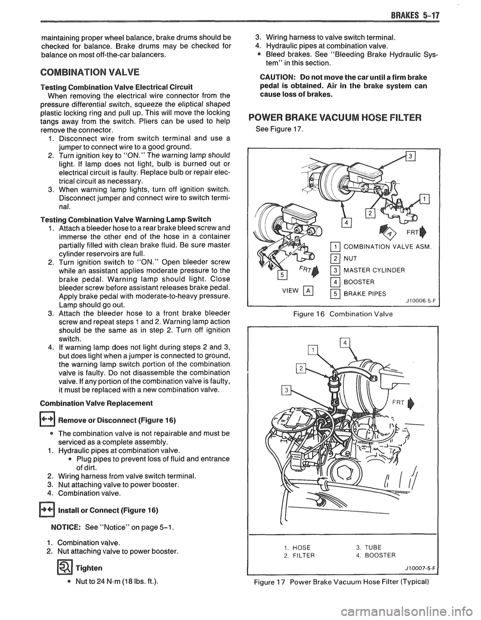
See Figure 17.
COMBINATION VALVE ASM.
MASTER CYLINDER BRAKE PIPES
Figure 16 Combination Valve
2 FILTER 4. BOOSTER
Figure 17 Power Brake Vacuum Hose Filter (Typical)
Page 319 of 1825

5814 DISC BRAKE CALIPER ASSEMBLY .
4. Inboard shoe and lining (6) by snapping retainer
spring (8) into piston (1) ID. Wear sensor (7)
should be at the leading edge of shoe during
forward wheel rotation. Shoe must lay flat against
piston.
5. Outboard
shoe and lining (5). Back of shoe must
lay flat against caliper.
6. Caliper as previously described.
7. Apply approximately
778
N (175 lb) force three
times to brake pedal to seat linings.
8. Position 12-inch channel lock pliers (19) over
brake shoe ears and bottom edge of caliper (13).
While holding moderate force (50 Ibs) on brake
pedal, clinch outboard shoe ears to caliper.
19. CHANNEL LOCK
PLIERS
Figure 58 1-1 0 Clinching Procedure
9. BOOT 10. PISTON 11. PISTON SEAL 12. BLEEDER VALVE 13. CALIPER HOUSING 20. SEAL GROOVE HMO01 1-5B1-BF
Figure 581-1 1 Caliper Assembly
UNIT REPAIR
CALIPER OVERHAUL
Tool Required:
J 26267 Boot Seal Installer (64 mm)
J 22904 Boot Seal Installer (74 mm)
J 28735 Boot Seal Installer (80 mm)
I
13. CALlP-ER HOUSING
I
Figure 58 1-1 2 Removing Piston
Disassemble (Figures 581-1 1 through 5B1-13)
1. Caliper completely from vehicle as previously
described.
2. Piston (10) using compressed air into the caliper
inlet hole.
CAUTION: Do not place fingers in
front of the piston in an attempt to
catch or protect it when applying
comrpessed air. This could result in
serious injury.
Important
e Use clean shop towels to pad the interior of
the caliper (13) during removal.
@ Piston (10) for:
e Scoring
Nicks
e Corrosion
e Worn or damaged chrome plating
e Replace piston if any of the above are found.
3. Boot (9), being careful not to scratch housing
bore,
4. Piston seal
(1 1) from groove (20) in caliper (13)
bore with a small wood or plastic tool. Do not use
a metal tool since this may damage caliper bore
or seal groove.
Inspect
@ Caliper bore and seal groove for:
e Scoring
e Nicks
e Corrosion
Wear
e Use crocus cloth to polish out light
corrosion.
@ Replace caliper housing if corrosion in and
around seal groove will not clean up with
crocus cloth.