1988 PONTIAC FIERO engine coolant
[x] Cancel search: engine coolantPage 876 of 1825
DRIVEABILITY AND EMISSIONS 5.0L (VIN F) & 5.7L (VIN 8) 6E3-C1-1
SECTION C1
ELECTRONlC CONTROL MODULE (ECM) AND SENSORS
CONTENTS
GENERAL DESCRIPTION ................ C1-I
ELECTRONIC CONTROL MODULE ....... C1-I
PJIEM-CAL......................... C1-I
ECM Function.. .................. C1-I
INFORMATION SENSORS ............. Cl-2
Engine Coolant Temperature Sensor . . C1-2
MAF Sensor ..................... C1-2
MAT Sensor .................... C1-2
Oxygen (02) Sensor. ............... C1-3
Throttle Position Sensor ............ C1-3
Knocksensor .................... C1-3
Vehicle Speed Sensor .............. C1-3
...... ParkINeutral Switch (Auto Only) C1-3
NC "ON" Signal .................. C1-4
Distributor Reference Signal ......... C1-4
DIAGNOSIS
......................... C1-4
ECM............................. C1-4
MEM-CAL......................... C1-4
ECMINPUTS....................... C1-4
........ Coolant Temperature Sensor C1-5
GENERAL DESCRIPTION
ELECTRONIC CONTROL MODULE (ECM)
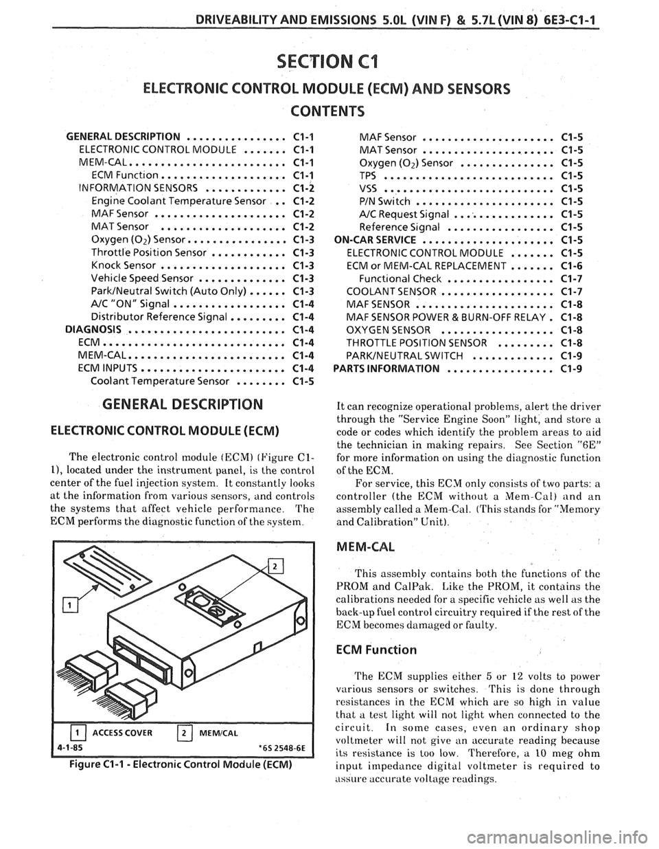
The electronic control [nodule (ECM) (Figure C1-
11, located under the instrument panel, is the control
center of the fuel injection system. It constantly looks
at the information from various sensors,
and controls
the systems that affect vehicle performance. The
ECM performs the diagnostic function of the system.
-- Figure C1-1 - Electronic Control Module (ECM)
MAF Sensor ..................... C1-5
MAT Sensor ..................... C1-5
Oxygen (02) Sensor ............... C1-5
TPS ........................... C1-5
VSS ........................... C1-5
PIN Switch ...................... C1-5
NC Request Signal ................ C1-5
Reference Signal ................. C1-5
ON-CAR SERVICE
..................... C1-5
ELECTRONIC CONTROL MODULE ....... C1-5
ECM or MEM-CAL REPLACEMENT ....... C1-6
Funct~onal Check ................. C1-7
COOLANT SENSOR .................. C1-7
MAFSENSOR ...................... C1-8
MAF SENSOR POWER & BURN-OFF RELAY . C1-8
OXYGEN SENSOR .................. C1-8
THROTTLE POSITION SENSOR ......... C1-8
PARKINEUTRAL SWITCH ............. C1-9
PARTS INFORMATION
................. C1-9
It can recognize operational problems, alert the driver
through the "Service Engine Soon" light, and store a
code or codes which identify the problem areas to aid
the technician in making repairs. See Section
"6E"
for more information on using the diagnostic function
of the
ECM.
For service, this ECM only consists of two parts: a
controller (the ECM without a
Mem-Cal) and an
assembly called a Mem-Cal. (This stands for "Memory
and Calibration" Unit).
M EM-CAL
This assembly contains both thc functions of thc
PROM and CalPak. Like the PROM, it contains the
calibrations needed for a specific vehicle as well as the
back-up fuel control circuitry required if the rest of the
ECM becomes damaged or faulty.
ECM Function
The ECM supplies either 5 or 12 volts to power
various sensors or switches.
This is done through
resistances in the ECM which are so high in value
that a test light will not light when connected to the
circuit.
In some cases, even an ordinary shop
voltmeter will not give an accurate reading because
its resistance is too low. Therefore, a
10 nleg ohm
input impedance digital voltmeter is
requircd to
assure accurate voltage readings.
Page 877 of 1825
6E3-61-2 S.OL (VIM F) & 5.7L (VIN 8) DRIVEABILITY AND EMISSIONS
The ECM controls output circuits such as the
injector, IAC, cooling fan relay, etc. by controlling the
ground circuit through transistors in the ECM.
INFORMATION SENSORS
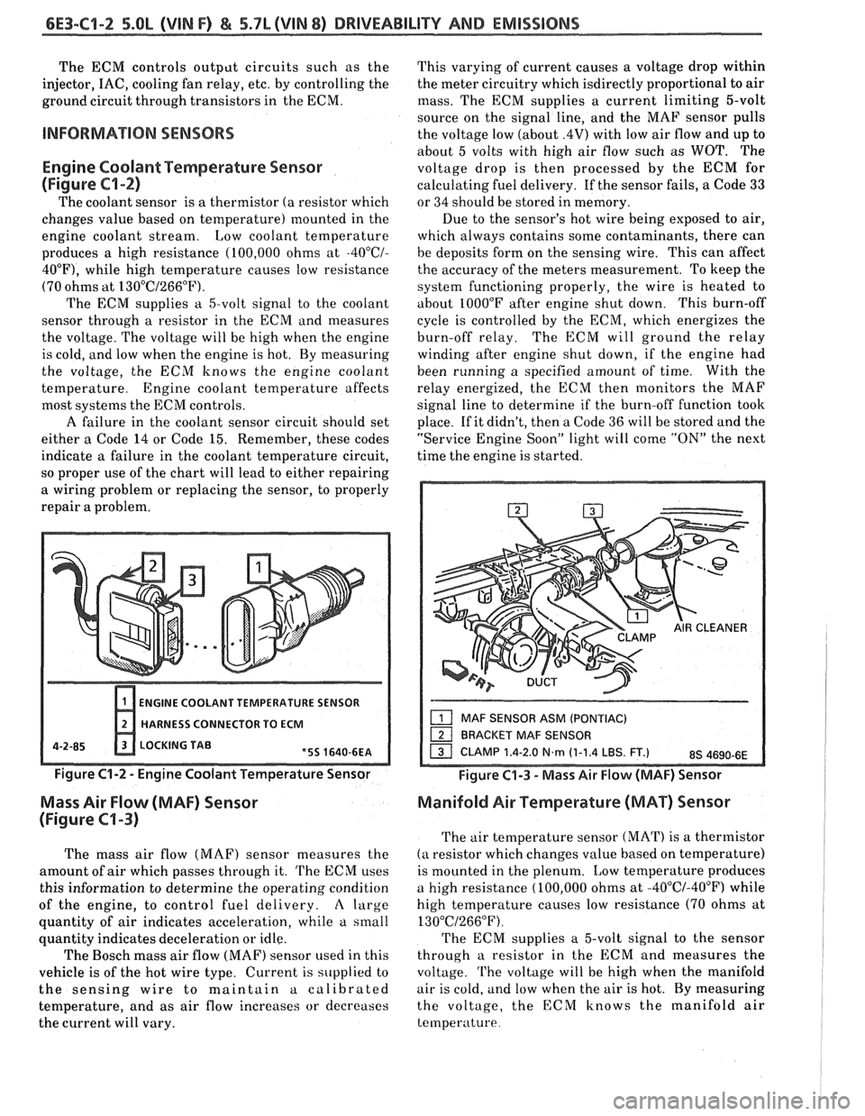
Engine Coolant Temperature Sensor
(Figure
Cl-2)
The coolant sensor is a thermistor (a resistor which
changes value based on temperature) mounted in the
engine coolant stream. Low coolant temperature
produces a high resistance (100,000 ohms at
-4O0C/-
40°F), while high temperature causes low resistance
(70 ohms at
130°C/266"F).
The ECM supplies a 5-volt signal to the coolant
sensor through
a resistor in the ECM and measures
the voltage. The voltage will be high when the engine
is cold, and low when the engine is hot. By measuring
the voltage, the ECM knows the engine coolant
temperature. Engine coolant temperature affects
most systems the
ECM controls.
A failure in the coolant sensor circuit should set
either a Code 14 or Code
15. Remember, these codes
indicate
a failure in the coolant temperature circuit,
so proper use of the chart will lead to either repairing
a wiring problem or replacing the sensor, to properly
repair
a problem.
ENGINE COOLANT TEMPERATURE SENSOR
HARNESS CONNECTOR TO
ECM
4-2-85 LOCKING TAE
Figure C1-2 - Engine Coolant Temperature Sensor
Mass Air Flow (MAF) Sensor
(Figure
C1-3)
The mass air flow (MAF) sensor measures the
amount of air which passes through it.
'l'he ECM uses
this information to determine the operating condition
of the engine, to control fuel delivery.
A large
quantity of air indicates acceleration, while a small
quantity indicates deceleration or idle.
The Bosch mass air flow
(MAF) sensor used in this
vehicle is of the hot wire type. Current is supplied to
the sensing wire to maintain a calibrated
temperature, and as air flow increases or decreases
the current will vary. This varying
of current causes a voltage drop within
the meter circuitry which isdirectly proportional to air
mass. The ECM supplies a current limiting 5-volt
source on the signal line, and the MAF sensor pulls
the voltage low (about
.4V) with low air flow and up to
about 5 volts with high air flow such as
WOT. The
voltage drop is then processed by the ECM for
calculating fuel delivery. If the sensor fails, a Code 33
or 34 should be stored in memory.
Due to the sensor's hot wire being exposed to air,
which always contains some contaminants, there can
be deposits form on the sensing wire. This can affect
the accuracy of the meters measurement. To keep the
system functioning properly, the wire is heated to
about
1000°F after engine shut down. This burn-off
cycle is controlled by the ECM, which energizes the
burn-off relay. The ECM will ground the relay
winding after engine shut down, if the engine had
been running a specified amount of time. With the
relay energized, the ECM then monitors the MAF
signal line to determine if the burn-off function took
place. If it didn't, then a Code 36 will be stored and the
"Service Engine Soon" light will come
"ON" the next
time the engine is started.
Figure C1-3 - Mass Air Flow (MAF) Sensor
Manifold Air Temperature (MAT) Sensor
The air temperature sensor (MAT) is a thermistor
(a resistor which changes value based on temperature)
is mounted in the plenum.
Low temperature produces
a high resistance (100,000 ohms at
-40°C/-40°F) while
high temperature causes low resistance (70 ohms at
130°C/266"F).
The ECM supplies a 5-volt signal to the sensor
through a resistor in the ECM and measures the
voltage. 'l'he voltage will be high when the manifold
air is cold, and low when the air is hot. By measuring
the voltage, the ECM knows the manifold air
temperature
Page 880 of 1825
DRIVEABILITY AND EMISSIONS 5.OL (VIN F) & 5.7L (VIN 8) 6E3-C1-5
Coolant Temperature Sensor
A "Scan" tool displays engine temperature in
degrees centigrade. After
engine is started, the
temperature should rise steadily to about 90°C then
stabilize when thermostat opens. If the engine has not
been run for several hours (overnight), the coolant
temperature and MAT temperatures should read close
to each other.
A fault in the coolant sensor circuit
should set a Code 14 or 15. The code charts also
contain a chart to check for sensor resistance values
relative to temperature. Voltage
should increase at
a steady rate as throttle is
moved toward WOT (about 4.6 volts).
The ECM has the ability to auto-zero the TPS
voltage if it is below about
.7V (700 mV). This means
that any voltage less than
.7 volts will be determined
by the ECM to be 0% throttle. A failure in the TPS or
circuit should set a Code 21 or 22.
VSS
A "Scan" tools reading should closely match with
speedometer reading with drive wheels turning. A
failure in the VSS circuit should set a Code 24.
MAF Sensor
PIN Switch
A "Scan" tool reads the MAF value and displays it
in grams per second and should read between 4-7 on a
fully warmed up idling engine. Values should change
rather quickly on acceleration, but values should
remain fairly stable
at any given rpm. Most "Scan"
tools will have 2 positions for reading MAF sensor
values (MAF
& air flow). Both values should read the
same if no Code 33 or 34 is set, but if a code is set, the
MAF values will be the default value and the air flow
parameter will lock on the value at which the ECM
recognized the fault.
A failure in the MAF sensor or
circuit should set a Code 33 or 34.
MAT Sensor
A "Scan" tool displays temperature of the air
entering the engine and should read close to ambient
air temperature when engine is cold, and rise as
underhood temperature increases. If the engine has
not been run for several hours (overnight) the MAT
sensor temperature and coolant temperature should
read close to each other. A failure in the MAT sensor
circuit should set a Code 23 or 25. The code charts also
contain a chart to check for sensor resistance values
relative to temperature.
02 Sensor
The "Scan" has several positions that will indicate
the state of the exhaust gases,
O2 voltage, integrator,
and block learn. See "Scan" position information in
introduction, Section
"6E".
A problem in the O2 sensor circuit or fuel system
should set
a Code 13 (open circuit), Code 44 (lean
indication), Code 45 (rich indication). Refer to
applicable chart if any of these codes were stored in
memory.
TPS
A "Scan" tool displays throttle position in volts.
The value should read
.54volts f .08 (.46V-.62V),
A "Scan" tool should read "PIN" when in park or
neutral and
"R.D.L." when in Drive. This reading
may vary with different makes of tools. Refer to
CHART
C-1A for PIN switch diagnosis.
NC Request Signal
"Scan" tool should indicate A/C "ON", when AIC is
requested and the pressure cycling switch is closed.
Reference Signal
A "Scan" tool will read this signal and is displayed
in rpm. See Section
"C4" for more information on the
ignition system.
ON-CAR SERVICE
ELECTRONIC CONTROL MODULE (ECM)
Service of the ECR4 should, normally, consist of
either replacement of the ECM or a Mem-Cal change.
If the diagnostic procedures call for the
ECM to be
replaced, the engine calibrator (Mem-Cal) and
ECM
should be checked first to see if they are the cu~ rcct
parts. If they are, remove the Mem-Cal frolri the
faulty ECM and install it in the new service L.:r.'Ni
'I'ITE SERVICE ECM WILL NOT CONTAIN A ME!vI-
CAL. Trouble Code 51 indicates the Mem-Cdi Is
installed improperly or has malfunctioned. W 1 ~:n
Code 51 is obtained, check the Mem-Cal installn(l~in
for bent pins or pins not fully seated in the sockct If
it is installed correctly and Code 51 still
shv 8,
replace the Mem-Cal.
Important
When replacing the production ECM will, :.I
service ECM (controller), it is important to
transfer the broadcast code and production Et'hl
number to the service ECM label.
with throttle closed and ignition "ON", or at iclle.
Page 882 of 1825
![PONTIAC FIERO 1988 Service Repair Manual
DRIVEABILITY AND EMISSIONS 5.OL (VIN F) & 5.7L (VIN 8) 6E3-C1-7
UPPER RADIATOR
/ MAF SENSOR ASM
1 CLAMP ASM 1.4-2.0 N-rn (1-1.4 LBS. FT.) 1 BOLTISCREW (2)
1 BRACI<ET MAF SENSOR I5] BOLTISCREW (2 PONTIAC FIERO 1988 Service Repair Manual
DRIVEABILITY AND EMISSIONS 5.OL (VIN F) & 5.7L (VIN 8) 6E3-C1-7
UPPER RADIATOR
/ MAF SENSOR ASM
1 CLAMP ASM 1.4-2.0 N-rn (1-1.4 LBS. FT.) 1 BOLTISCREW (2)
1 BRACI<ET MAF SENSOR I5] BOLTISCREW (2](/manual-img/50/57415/w960_57415-881.png)
DRIVEABILITY AND EMISSIONS 5.OL (VIN F) & 5.7L (VIN 8) 6E3-C1-7
UPPER RADIATOR
/ MAF SENSOR ASM
1 CLAMP ASM 1.4-2.0 N-rn (1-1.4 LBS. FT.) 1 BOLTISCREW (2)
1 BRACI
Install or Connect (Figure C1-9)
1. Mem-Cal in Mem-Cal socket.
Important
Press only on the ends of the Mem-Cal.
Small notches in the Mem-Cal must be aligned
with the small notches in the Mem-Cal socket.
Press on the ends of the Mem-Cal until the
retaining clips snap into the ends of the Mem-Cal.
Do not press on the middle of the Mem-Cal, only
on the ends.
2. Access cover on ECM.
3. ECM in passenger compartment.
4. Connectors to ECM.
5. Right hand hush panel.
6. Negative battery cable.
Functional Check
1. Turn ignition "ON".
2. Enter diagnostics.
A. Allow Code
12 to flash four times to verify no
other codes are present.
This indicates the Mem-Cal is installed
properly and the ECM is functioning.
B. If trouble Code 51 occurs, or if the "Service
Engine Soon" light is "ON" constantly with no
codes, the Mem-Cal is not fully seated or is
defective.
@ If not fully seated, press firmly on the ends
of the Mem-Cal.
If it is necessary to remove the Mem-Cal,
follow the previous removal instructions.
COOLANT SENSOR
NOTICE:
Care must be taken when handling
coolant sensor. Damage to coolant sensor
will affect proper operation of the fuel
injection system.
Remove or Disconnect
1. Negative battery cable.
2. Air inlet duct.
3. Electrical connector.
4. Carefully back out coolant sensor.
Install or Connect
1. Sensor in engine.
2. Electrical connector.
3. Air inlet tube.
4. Negative battery cable.
ENGINE HARNESS ASM
Figure Cl-1 l Relays
Page 888 of 1825
DRIVEABILITY AND EMISSIONS 5.OL (VIN F) & 5.7L (VIN 8) 6E3-C2-1
SECTION C2
FUEL CONTROL SYSEENI
CONTENTS
GENERAL DESCRIPTION . . . . . . . . . . . . . . . . C2-1
PURPOSE ........................ C2-1
MODES OF OPERATION . . . . . . . . . . . . . . C2-2
Starting Mode . . . . . . . . . . . . . . . . . . . C2-2
Clear Flood Mode.. . . . . . . . . . . . . . . . C2-2
Run Mode.. . . . . . . . . . . . . . . . . . . . . . C2-2
Acceleration Mode.. . . . . . . . . . . . . . . C2-2
Deceleration Mode . . . . . . . . . . . . . . . C2-3
Battery Voltage Correction Mode . . . . . C2-3
Fuel Cutoff Mode . , . . . . . . . . . . . . . . . C2-3
FUEL CONTROL SYSTEM . . . . . . . . . . . . . . C2-3
Basic System Operation . . . . . . . . . . . . C2-3
Throttle Body Unit . . . . . . . . . . . . . . . . C2-3
Fuel Rail . . . . . . . . . . . . . . . . . . . . . . . C2-3
Fuel Injectors . . . . . . . . . . . . . . . . . . . . C2-3
Pressure Regulator . . . . . . . . . . . . . . . C2-4
IAC Valve . . . . . . . . . . . . . . . . . . . . . . . C2-4
Fuel Pump Electrical Circuit . . . . . . . . , C2-5
DIAGNOSIS
......................... C2-5
FUEL CONTROL SYSTEM . . . . . . . . . . . . . . C2-5
IDLE AIR CONTROL VALVE . . . .. 0.. . a. C2-5
FUEL SYSTEM PRESSURE TEST . .. . . . . . . C2-5
ON-CAR SERVICE
. . . . . . . . . . . . . . . . . . . . . C2-5
PORT FUEL INJECTION COMPONENTS . . . . C2-5
FUEL PRESSURE RELIEF PROCEDURE . . . . . C2-5
Plenum ........................ C2-5
FUEL RAlL ASSEMBLY . . . . . . . . . . . . . . . . C2-6
FUEL
RAlL SERVICE . . . . . . . . . . . . . . . . . . . C2-7
IDENTIFICATION . . . . . . . . . . . . . . . . . . . C2-7
UNlT SERVICE PROCEDURES .. . . . . . . . .. C2-7
COLD START TUBE & VALVE ASSEMBLY.. . C2-7
PARTS INFORMATION
. . . . . . . . . . . . . . . C2-9
FUEL PRESSURE CONNECTION ASSY. . . . . C2-10
FUEL INJECTORS (Rail Removed) . . . . . . . . C2-10
PRESSURE REGULATOR (Rail Removed) . . . C2-10
COLD START FUEL INJECTION SWITCH . . . C2-11
THROTTLEBODY ................... C2-11
THROTTLE BODY SERVICE IDENTIFICATION
. C2-12
UNlT REPAIR PROCEDURES . . . . . . . . . . . . C2-12
TPS Adjustment .............. C2-12
MINIMUM IDLE SPEED CHECK . . . . . . . . . . . C2-12
PARTSINFORMATION ................. C2-15
IDLE AIR C'NT' L VALVE ASSY & GASKET . . C2-15
CLEAN AIR COVER &GASKET . . . . . . . . . . C2-15
IDLE AIR CONTROUCOOLANT CVR. ASSY . C2-15
Throttle Body Removed From Engine . . C2-15
FUEL PUMP RELAY . . . . . . . . . . . . . .,. . . . C2-16
OIL PRESSURE SWITCH . . . . . . . . . . . . . . . C2-16
PARTS INFORMATION . . . . . . . . . . . . . . . . . C2-16
GENERAL DESCRIPTION
PURPOSE
The basic function of the fuel control system is to
control fuel delivery to the engine.
Fuel is delivered to the engine by individual fuel
injectors mounted in the intake manifold near each
cylinder.
The main control sensor is the oxygen
(02) sensor,
which is located in the exhaust manifold. The
O2
sensor tells the electronic control module (ECM) how
much oxygen is in the exhaust gas.
The ECM changes
the
airlfuel ratio to the engine by controlling the fuel
injectors.
The best mixture to minimize exhaust
emissions is
14.7 to 1, which allows the catalytic
converter to operate the most efficiently. Because of
the constant measuring and adjusting of the
airlfuel
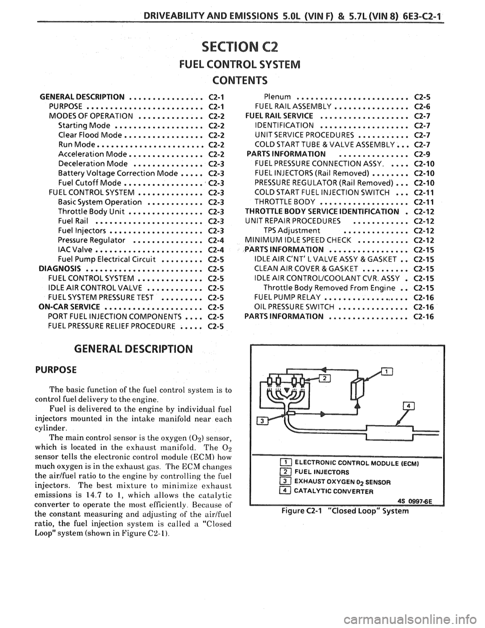
ratio, the fuel injection system is called a "Closed
Loop" system (shown in Figure
C2-I).
EXHAUST OXYGEN 02 SENSOR
CATALYTIC CONVERTER
Figure C2-1 "Closed Loop" System
Page 889 of 1825
6E3-C2-2 5.OL (VIN F) & 5.7L(VIN 8) DRIVEABILITY AND EMISSIONS
MODES OF OPERATION
The ECM looks at voltages from several sensors to
determine how much fuel to give the engine. The fuel
is delivered under one of several conditions, called
"modes". All the modes are controlled by the ECM
and are described below.
Starting Mode
When the ignition is first turned "ON", the ECM
will turn "ON" the fuel pump relay for two seconds,
and the fuel pump will build up pressure. The ECM
then checks the coolant temperature sensor, throttle
position sensor, and determines the proper airlfuel
ratio for starting. This ranges from 1.5
: 1 at -36°C
(-33°F) to 14.7:l at 94°C (201°F). The ECM controls
the amount of fuel delivered in the starting mode by
changing how long the injectors are pulsed "ON".
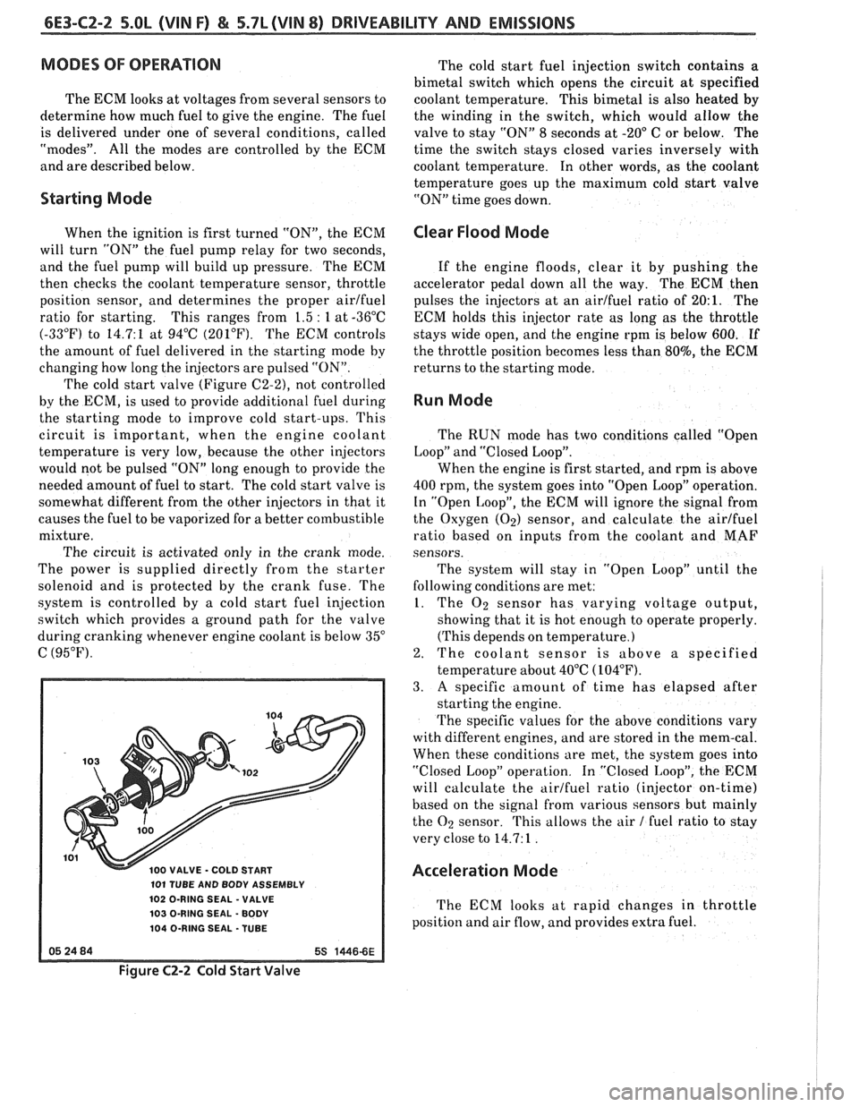
The cold start valve
(Figure C2-2), not controlled
by the ECM, is used to provide additional fuel during
the starting mode to improve cold start-ups. This
circuit is important, when the engine coolant
temperature is very low, because the other injectors
would not be pulsed "ON" long enough to provide the
needed amount of fuel to start. The cold start valve is
somewhat different from the other injectors in that it
causes the fuel to be vaporized for a better combustible
mixture.
The circuit is activated only in the crank mode.
The power is supplied directly from the starter
solenoid and is protected by the crank fuse. The
system is controlled by a cold start fuel injection
switch which provides a ground path for the valve
during cranking whenever engine coolant is below
35"
C (95°F).
100 VALVE - COLD START
101 TUBE AND BODY ASSEMBLY
102 O-RING SEAL
- VALVE
103 O-RING SEAL
- BODY
104 O-RING SEAL -TUBE
The cold start fuel injection switch contains a
bimetal switch which opens the circuit at specified
coolant temperature. This bimetal is also heated
by
the winding in the switch, which would allow the
valve to stay "ON" 8 seconds at
-20" C or below. The
time the switch stays closed varies inversely with
coolant temperature. In other words, as the coolant
temperature goes up the maximum cold start valve
"ON" time goes down.
Clear Flood Mode
If the engine floods, clear it by pushing the
accelerator pedal down all the way. The ECM then
pulses the injectors at an airlfuel ratio of
20:l. The
ECM holds this injector rate as long as the throttle
stays wide open, and the engine rpm is below 600.
If
the throttle position becomes less than 80%, the ECM
returns to the starting mode.
Run Mode
The RUN mode has two conditions called "Open
Loop" and "Closed Loop".
When the engine is first started, and rpm is above
400 rpm, the system goes into "Open Loop" operation.
In "Open Loop", the ECM will ignore the signal from
the Oxygen
(Oz) sensor, and calculate the airlfuel
ratio based on inputs from the coolant and MAF
sensors.
The system will stay in
"Open Loop" until the
following conditions are met:
1. The O2 sensor has varying voltage output,
showing that it is hot enough to operate properly.
(This depends on temperature.)
2. The coolant sensor is above a specified
temperature about 40°C
(104°F).
3. A specific amount of time has elapsed after
starting the engine.
The specific values for the above conditions vary
with different engines, and are stored in the mem-cal.
When these conditions are met, the system goes into
"Closed Loop" operation. In "Closed Loop", the ECM
will calculate the airlfuel ratio (injector on-time)
based on the signal from various sensors but
mainly
the O2 sensor. This allows the air 1 fuel ratio to stay
very close to 14.7: 1
.
Acceleration Mode
The ECM looks at rapid changes in throttle
position and air flow, and provides extra fuel.
Figure C2-2 Cold Start Valve
Page 890 of 1825
DRIVEABILITY AND EMISSIONS 5.OL (VIN F) & 5.7L (VIN 8) 6E3-CZ-3
Deceleration Mode
The ECM looks at changes in throttle position and
air flow to reduce the amount of fuel. When
deceleration is very fast, the ECM may shut off fuel
completely for short periods.
Battery Voltage Correction Mode
When battery voltage is low, the ECM can
compensate for the weak spark delivered by the
distributor by:
@ Increasing the amount of fuel delivered;
@ Increasing the idle rpm; and
@ Increasing ignition dwell time.
Fuel Cutoff Mode
No fuel is delivered by the injector when the
ignition is "OFF". This prevents dieseling. Also, fuel
is not delivered if no reference pulses are seen from
the distributor, which means the engine is not
running. This prevents flooding.
FUEL CONTROL SYSTEM
Basic System Operation
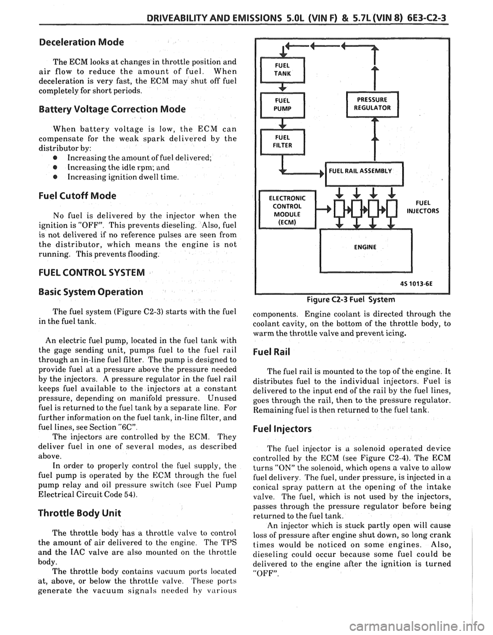
The fuel system (Figure C2-3) starts with the fuel
in the fuel tank.
An electric fuel pump, located in the fuel tank with
the gage sending unit, pumps
fuel to the fuel rail
through an in-line fuel filter. The pump is designed to
provide fuel at a pressure above the pressure needed
by the injectors. A pressure regulator in the fuel rail
keeps fuel available to the injectors at
a constant
pressure, depending on manifold pressure. Unused
fuel is returned to the fuel tank by a separate line. For
further information on the fuel tank, in-line filter, and
fuel lines, see Section
"6C".
The injectors are controlled by the ECM. They
deliver fuel in one of several modes, as described
above. In order to properly control the fuel supply, the
fuel pump is operated by the
ECM through the fuel
pump relay and oil pressure switch (see Fuel Pump
Electrical Circuit Code
54).
Throttle Body Unit
The throttle body has a throttle valve to control
the amount of air delivered to the engine. The TPS
and the IAC valve are also mounted on the throttle
body. The throttle body contains vacuum ports located
at, above, or below the
throttIe valve. 'I'hese ports
generate the vacuum signals
needed I,y v~irious
Figure C2-3 Fuel System
components. Engine coolant is directed through the
coolant cavity, on the bottom of the throttle body, to
warm the throttle valve and prevent icing.
Fuel Rail
The fuel rail is mounted to the top of the engine. It
distributes fuel to the individual injectors. Fuel is
delivered to the input end of the rail by the fuel lines,
goes through the rail, then to the pressure regulator.
Remaining fuel is then returned to the fuel tank.
Fuel Injectors
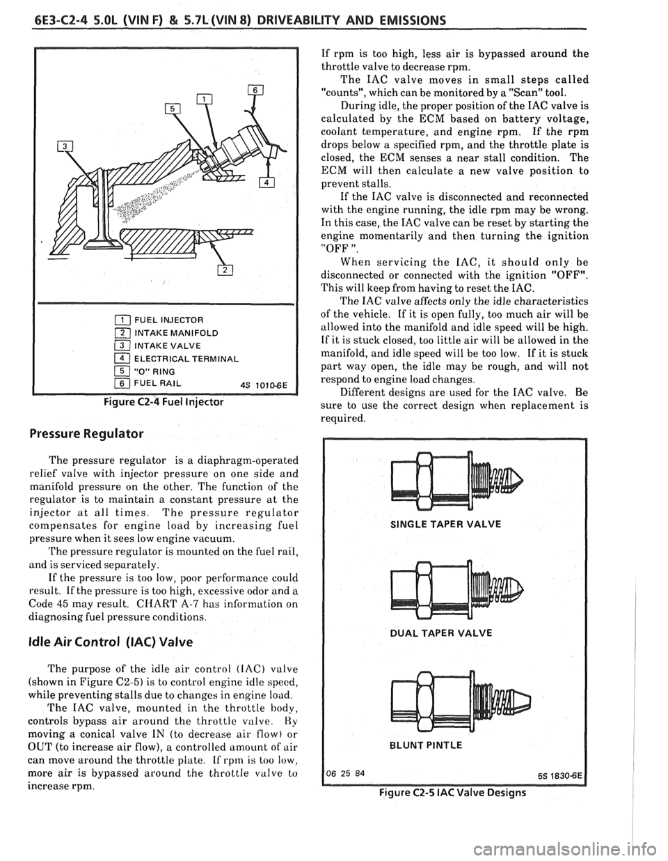
The fuel injector is a solenoid operated device
controlled by the ECM (see Figure
C2-4). The ECM
turns
"ON" the solenoid, which opens a valve to allow
fuel delivery.
The fuel, under pressure, is injected in a
conical spray pattern at the opening of the intake
valve. The fuel, which is not used by the injectors,
passes through the pressure regulator before being
returned to the fuel tank.
An injector which is stuck partly open will cause
loss of pressure after engine shut down, so long crank
times would be noticed on some engines. Also,
dieseling could occur because some fuel could be
delivered to the engine after the ignition is turned
"OFF".
Page 891 of 1825
6E3-CZ-4 5.OL (VIN F) & 5.7L(VIN 8) DRIVEABILITY AND EMISSIONS
FUEL INJECTOR
1 INTAKE MANIFOLD
( INTAKE VALVE
1 ELECTRICAL TERMINAL
Figure C2-4 Fuel Injector
Pressure Regulator
The pressure regulator is a diaphragm-operated
relief valve with injector pressure on one side and
manifold pressure on the other. The function of the
regulator is to maintain a constant pressure at the
injector at all times. The pressure regulator
cotnpensates for engine load by increasing fuel
pressure when it sees low engine vacuum.
The pressure regulator is mounted on the fuel rail,
and is serviced separately.
If the pressure
is too low, poor performance could
result. If the pressure is too high, excessive odor and a
Code
45 may result. CHART A-7 has information on
diagnosing fuel pressure conditions.
Idle Air Control (IAC) Valve
The purpose of the idle air control (IAC) valve
(shown in Figure
C2-5) is to control engine idle speed,
while preventing stalls due to changes in engine load.
The IAC valve, mounted in the throttle body,
controls bypass air around the throttle
valve. Hy
moving a conical valve IN (to decrease air flow) or
OUT (to increase air flow), a controlled amount of air
can move around the throttle plate. If rpm is too low.
more air
is bypassed around the throttle valve to
increase rpm. If
rpm is too high, less air is bypassed around the
throttle valve to decrease rpm.
The IAC valve moves in small steps called
"counts", which can be monitored by a "Scan" tool.
During idle, the proper position of the IAC valve is
calculated by the ECM based on battery voltage,
coolant temperature, and engine rpm. If the rpm
drops below
a specified rpm, and the throttle plate is
closed, the ECM senses a near stall condition. The
ECM will then calculate a new valve position to
prevent stalls.
If the IAC valve is disconnected and reconnected
with the engine running, the idle rpm may be wrong.
In this case, the IAC valve can be reset by starting the
engine momentarily and then turning the ignition
"OFF
".
When servicing the IAC, it should only be
disconnected or connected with the ignition "OFF".
This will keep from having to reset the IAC.
The IAC valve affects only the idle characteristics
of the vehicle. If it is open fully, too much air will be
allowed into the manifold and idle speed will be high.
If it is stuck closed, too little air will be allowed in the
manifold, and idle speed will be too low. If it is stuck
part way open, the idle may be rough, and will not
respond to engine load changes.
Different designs are used for the IAC valve. Be
sure to use the correct design when replacement is
required.
SINGLE TAPER VALVE
DUAL TAPER VALVE
BLUNT
PINTLE
Figure C2-5 IAC Valve Designs