1988 PONTIAC FIERO engine coolant
[x] Cancel search: engine coolantPage 1122 of 1825
AUTOMATIC TMNSMISSION ON-VEHICLE SERVICE 7A1-3
e Propeller shaft oil seal worn or damaged
o Governor cover
e Line pressure pipe plug loose
@ Porous casting
3. Leak at converter end:
Converter seal damaged
- Seal lip cut. (Check converter hub for
damage.)
- Bushing moved forward and damaged
- Garter spring missing from seal
o Converter leak in weld area. (Refer to
Torque Converter.)
Porous casting (Case or pump)
4. Fluid comes out vent pipe or fill tube:
Over-filled
Water or coolant in fluid. Fluid will appear
milky.
e Case porous
e Incorrect fluid level indicator
e Plugged vent
e Drain back holes plugged
Mispositioned oil pump to case gasket (if
equipped)
Case Porosity Repair
1. Clean the leak area with solvent and air dry.
CAUTION: Epoxy adhesive may cause
skin irritations and eye damage. Read
and follow all information on the
container label as provided by the
manufacturer.
2. Mix a sufficient amount of epoxy adhesive,
# 1052533, or equivalent, following the
manufacturer's recommendations.
3. While the transmission case is hot, apply epoxy
adhesive with a clean, dry soldering acid brush.
4. Allow the epoxy adhesive to cure for three hours
before starting the engine.
5. Repeat fluid leak diagnosis procedures.
TORQUE CONVERTER CLUTCH ELECTRICAL
CONTROLS
The Torque Converter Clutch (TCC) system uses
controls that are internal as well as external to the
transmission. For internal control components of the
TCC system, refer to the I-Iydraulic Diagnosis Section
for for wiring diagrams and switch locations.
The external control components of the TCC
system include:
1. Brake Release Switch - To avoid stalling the
engine when braking, the converter clutch is
released any time the brakes are applied.
2. Electronic Control ModuOe - Receives input
signals and grounds TCC solenoid to apply clutch
when proper operating conditions are met.
3. Throttle Position Sensor - Sends throttle
position information to Electronic Control
Module.
4. Vacuum Sensor - Sends engine vacuum (load)
information to Electronic Control Module.
5. Vehicie Speed Sensor - Sends vehicle speed
information to Electronic Control Module.
6. Coolant Temperature Sensor - Sends engine
coolant temperature information to Electronic
Control Module.
TORQUE CONVERTER CLUTCH DIAGNOSIS
To properly diagnose the Torque Converter
Clutch (TCC) system perform all electrical testing first
and then the hydraulic testing. Refer to the appropriate
Driveability and Emissions Section (6E) for additional
Torque Converter Clutch Information
ON-VEHICLE SERVICE
SI-IIFT CONTROL CABLE
Remove or Disconnect (Fig. 1)
1. Negative battery cable.
2. Raise car, see Section OA.
3. Cable attachments at transmission.
4. Lower car.
5. Console, see Section
8C.
6. Cable at control lever and base.
7. Cable from floor.
install or Connect
1. Cable to floor.
2. Cable at base and control lever.
3. Console, see Section 8C.
4. Place control lever in "NEUTRAL"
5. Raise car.
6. Cable attachments at transmission.
7. Adjust cable.
8. Lower car.
9. Negative battery cable.
Adjust (Fig. 1)
1. Place control lever in "N" (Neutral).
2. Raise car, see Section 0.4.
3. Loosen cable
attachment at shift lever.
4. Rotate shift lever "clockwise" to park detent and
then back to neutral.
5. Tighten cable attachment.
15
N-m (11 lbs. ft.)
Important
Levg must be held out of "PARK" when
torquing nut.
6. Lower car.
7. Check cable adjustment by rotating control lever
thru the detents.
Remove or Disconnect (Fig. 2)
1. Negative battery cable.
2. Console, see Section 8C.
3. Cable at control lever and base.
Page 1166 of 1825
CONTENTS
ELECTRICAL DIAGNOSIS
Cell
1
2
3
4 5
10
11
12 14
20
21
22
23
30
31
33
34
40
4
1
60
61
62
63
64
65
66
67
68
Index
Introduction
Symbols
Troubleshooting Procedures Repair Procedures
Power Distribution
Fuse Block Details
Light Switch Details
Ground Distribution
Engine:
V6 VIN S
Engine: V8 VIN
F
Engine: V8 VIN E
Engine:
V8 VIN 8
Starter and Charging System
Coolant Fans
Vehicle Speed Sensor
Cruise Control Horns
Brake Warning System
Heater
Defogger
Air Conditioning: System Check
Air Conditioning: Blower Controls
Air Conditioning: Compressor Controls
Air Conditioning: Air Delivery
Air Conditioning: Blower Controls
Air Conditioning: Compressor Controls
Air Conditioning: Air Delivery Cell
77
8
1
82
86 90
9
1
100
102
103
110
111
112
114
117
120
130
133
134
135
141
143
145
150
151
201 202
203
Warnings and Alarms: Chime
Instrument Panel: Gages Cluster
Instrument Panel:
Digital Cluster
Driver Information Center
(DIC)
WiperlWasher
WiperlWasher: Pulse
Headlights
Headlight Doors
Headlights with Lamp Monitor
Exterior Lights
Exterior Lights with Lamp Monitor
Back Up Lights
Interior Lights
Interior Lights Dimming
Power Windows
Power Door Locks
Theft Deterrent
Hatch Release
Hatch Pull-Down
Power Mirrors
Automatic Day-Night Mirror
Lumbar Support
Radio Power Antenna
Component Location Views
Harness Connector Faces
Harness Routing Views
Page 1167 of 1825
Page
Air Conditioning
Air Delivery
Electronic
.................... 68-0
Manual
....................... 65-0
Blower Controls
Electronic
.................... 66-0
Manual
....................... 63-0
Compressor Controls Electronic
.................... 67-0
Manual
....................... 64-0
................... System Check 62-0
Alarms (Audible)
Chime
......................... 77-0
Antenna(Power) ................... 151-0
Brakes
................. Warning System 41-0
................... Charging system 30-7
...................... Cigar Lighter 114-0
Circuit Breaker Details
PWR ACC Circuit
.......... Breaker 10.1.10.3.10.5.1 1.3
WDO Circuit Breaker
10.1. 10.3. 10.5. 11-4
.......... Component Location Views 201-0
Connectors (Harness Connector Faces) 202-0
el00 .......................... 202-0
............... Junction Block ((2238) 202-2
Coolant Fan
....................... 31-0
Cruise Control
..................... 34-0
Defogger
......................... 61-0
Digital Clock
...................... 150-0
Displays Digital Cluster
.................. 82-0
Coolant Temperature
........... 82-2
Page
......................... Fuel 82-3
................... Oil Pressure 82-2
.................. Speedometer 82-3
................. Door Locks (Power) 130-0
...... Driver Information Center (DIC) 86-0
Engines
... Multi-Port Fuel Injection (VIN S) 20-0
.... Multi-Port Fuel Injection (VIN 8) 23-0
.... Throttle
Body Injection (VIN E) 22-0
...... Tuned
Port Injection (VIN F) 21-0
................. Fuse Block Details 11-0
Fuse Details
........... INST LP 10.0.10.2.10.4.1 1.1
.............. TAIL 10.0.10.2.10.4.1 1.2
................ CRANK 10.0.10.2.1 0.4
.............. CTSY 10~0.10.2.10.4.1 1.2
......... STOP HAZ 10.1.10.3.10.5.1 1.3
............ RADIO 10.1.10.3.10.5.1 1.4
............ WIPER 10.1.10.3.10.5.1 1.4
.................... HATCH 10.2.1 0.4
........... HTR AlC 10.1.10.3.10.5.1 1.4
........... CIH.FAN 10.1.10.3.10.5.1 1.4
......... TURN BIU 10.1.10.3.10.5.1 1.4
............ GAGES 10.1.10.3.10.5.1 1.4
ECM-IGN
(V6 VIN S. V8 VIN F.
........ V8 VIN 8. V8 VIN E) 10.1.1 1.7
............ INJ 1 (V6 VIN S) 10.1.1 1.10
......... FPIINJ 2 (V6 VIN S) 10.1.1 1.10
... INJ 1 (V8 VIN F. V8 VIN 8) 10.3.1 1.11
FPIINJ 2 (V8 VIN F. V8 VIN 8) 10.3.1 1.11
............ CLSTR 10.1.10.3.10.5.1 1.13
............. FPIINJ 2 (V8 VIN E) 11-12
Page
Gages
................... Gages Cluster 81-0
........... Coolant Temperature 81-2
......................... Fuel 81-3
................... Oil Pressure 81-2
.................. Speedometer 81-3
................ Ground Distribution 14-0
Harness Routing Views
............. 203-0
........................... Heater 60-0
............................ Horns 40-0
Indicators
.................. Digital Cluster 82-0
................ Brake Warning 82-4
.................. Fasten Belts 82-1
...................... Hi Beam 82-1
...................... Security 82-1
............ Service Engine Soon 82-4
......................... Shift 82-5
......................... Turn 82-1
................... Gages Cluster 81-0
................ Brake Warning 81-0
.................. Fasten Belts 81-0
...................... Hi Beam 81-0
............ Service Engine Soon 81-0
......................... Shift 81-1
......................... Turn 81-0
Instrument Panel
Digital Cluster
.................. 82-0
Gages Cluster
................... 81-0
............ Interior Lights Dimming 117-0
...................... Introduction 2-0
Lights (Exterior)
........................ Back Up 112-0
...................... Fog 100.3,10 3.0
Page 1202 of 1825
REPAIR PROCEDURES m I L
REPAlRlNG METRI-PACK SERIES 150
CONNECTORS
(Pull-to-Seat Type)
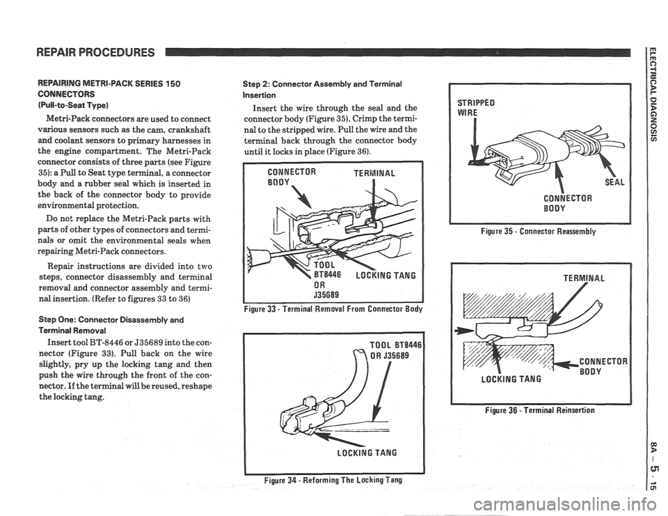
Metri-Pack connectors are used to connect
various sensors such as the cam, crankshaft
and coolant sensors to primary harnesses in
the engine compartment. The Metri-Pack
connector consists of three parts (see Figure
35): a Pull to Seat type terminal, a connector
body and
a rubber seal which is inserted in
the back of the connector body to provide
environmental protection.
Do
nc: replace the Metri-Pack parts with
parts of other types of connectors and termi-
nals or omit the environmental seals when
repairing Metri-Pack connectors.
Repair instructions are divided into
two
steps, connector disassembly and terminal
removal and connector assembly and termi-
nal insertion. (Refer to figures
33 to 36)
Step One: Connector Disassembly and
Terminal Removal
Insert tool BT-8446 or 535689 into the con-
nector (Figure
33). Pull back on the wire
slightly, pry up the locking tang and then
push the wire through the front of the con-
nector. If the terminal will be reused, reshape
the locking tang.
Step 2: Connector Assembly and Terminal
Insertion
Insert the wire through the seal and the
connector body (Figure
35). Crimp the termi-
nal to the stripped wire. Pull the wire and the
terminal back through the connector body
until it locks in place (Figure
36).
NECTOR TERMINAL
BT8446 LOCKING TANG
Figure 33
- Terminal Removal From Connector Body
TOOL
BT8446
Figure 35 - Connector Reassembly
Figure 36
- Terminal Reinsertion
Page 1210 of 1825
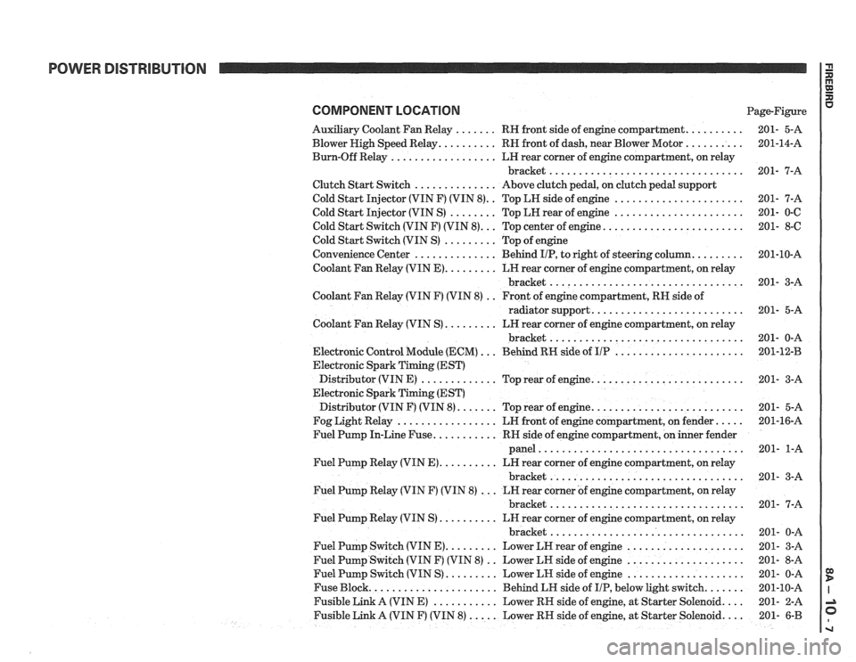
BOWER DISTRIBUTION
COMPONENT LOCATION Page-Figure
Auxiliary Coolant Fan Relay
. . . . . . . RH front side of engine compartment. . . . . . . . . .
Blower High Speed Relay. . . . . . . . . . RN front of dash, near Blower Motor . . . . . . . . . .
Burn-Off Relay . . . . . . . . . . . . . . . . . . LH rear corner of engine compartment, on relay
bracket
.................................
Clutch Start Switch . . . . . . . . . . . . . . Above clutch pedal, on clutch pedal support
Cold Start Injector (VIN F) (VIN
8). . Top LH side of engine . . . . . . . . . . . . . . . . . . . . . .
Cold Start Injector (VIN S) . . . . . . . . Top LH rear of engine . . . . . . . . . . . . . . . . . . . . . .
Cold Start Switch (VIN F) (VIN 8). . . Top center of engine. . . . . . . . . . . . . . . . . . . . . . . .
Cold Start Switch (VIN S) . . . . . . . . . Top of engine
Convenience Center
. . . . . . . . . . . . . . Behind IIP, to right of steering column. . . . . . . . .
Coolant Fan Relay (VIN E). . . . . . . . . LN rear corner of engine compartment, on relay
bracket
.................................
Coolant Fan Relay (VIN F) (VIN 8) . . Front of engine compartment, RH side of
radiator support.
. . . . . . . . . . . . . . . . . . . . . . . . .
Coolant Fan Relay (VIN S) . . . . . . . . . LH rear corner of engine compartment, on relay
bracket
.................................
Electronic Control Module (ECM) . . . Behind RN side of UP . . . . . . . . . . . . . . . . . . . . . .
Electronic Spark Timing (EST)
Distributor (VIN E)
. . . . . . . . . . . . . Top rear of engine. . . . . . . . . . . . . . . . . . . . . . . . . .
Electronic Spark Timing (EST)
Distributor (VIN F) (VIN
8). . . . . . . Top rear of engine. . . . . . . . . . . . . . . . . . . . . . . . . .
Fog Light Relay . . . . . . . . . . . . . . . . . LR front of engine compartment, on fender. . . . .
Fuel Pump In-Line Fuse. . . . . . . . . . . RR side of engine compartment, on inner fender
panel
...................................
Fuel Pump Relay (VIN E). . . . . . . . . . LN rear corner of engine compartment, on relay
bracket
.................................
Fuel Pump Relay (VIN F) (VIN 8) . . . LN rear corner of engine compartment, on relay
bracket
.................................
Fuel Pump Relay (VIN S) . . . . . . . . . . LH rear corner of engine compartment, on relay
bracket
.................................
Fuel Pump Switch (VIN E). . . . . . . . . Lower LN rear of engine . . . . . . . . . . . . . . . . . . . .
Fuel Pump Switch (VIN F) (VIN 8) . . Lower LN side of engine . . . . . . . . . . . . . . . . . . . .
Fuel Pump Switch (VIN S) . . . . . . . . . Lower LN side of engine . . . . . . . . . . . . . . . . . . . .
Fuse Block. . . . . . . . . . . . . . . . . . . . . . Behind LH side of IIP, below light switch. . . . . . .
Fusible Link A (VIN E) . . . . . . . . . . . Lower RN side of engine, at Starter Solenoid. . . .
Fusible Link A (VIN F) (VIN 8) . . . . . Lower RH side of engine, at Starter Solenoid. . . . 201- 6-B
Page 1250 of 1825
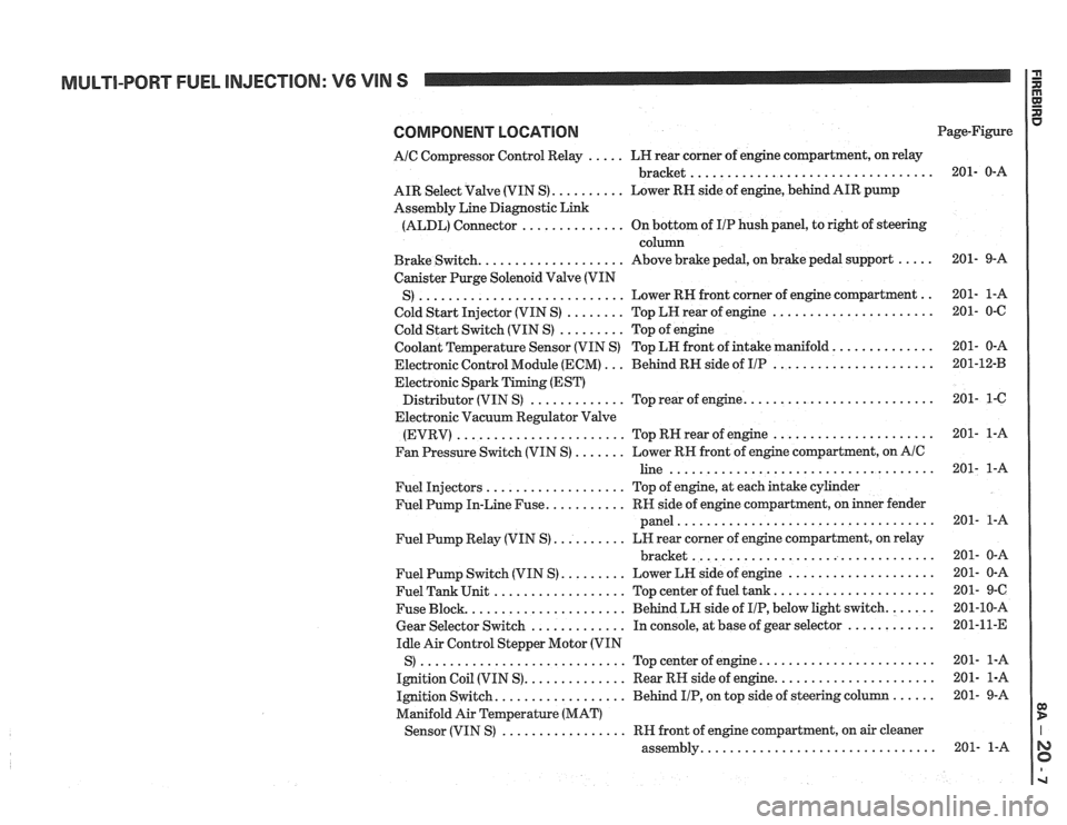
MULTI-PORT FUEL INJECTION: V6 VIN S
COMPONENT LOCATION
AIC Compressor Control Relay ..... LH rear corner of engine compartment, on relay
................................. bracket
AIR Select Valve (VIN S)
.......... Lower RN side of engine, behind AIR pump
Assembly Line Diagnostic Link
(ALDL) Connector
.............. On bottom of IIP hush panel, to right of steering
column
Brake Switch.
................... Above brake pedal, on brake pedal support .....
Canister Purge Solenoid Valve (VIN
............................ .. S) Lower RH front
corner of engine compartment
Cold Start Injector (VIN S)
........ Top LH rear of engine ......................
Cold Start Switch (VIN S) ......... Top of engine
Coolant Temperature Sensor (VIN S) Top LN front of intake manifold.
.............
Electronic Control Module (ECM) ... Behind RH side of IIP ......................
Electronic Spark Timing (EST)
......................... Distributor (VIN S) ............. Top rear of engine.
Electronic Vacuum Regulator Valve
(EVRV)
....................... TopRHrearofengine ......................
Fan Pressure Switch (VIN S) ....... Lower RH front of engine compartment, on AIC
line ....................................
Fuel Injectors ................... Top of engine, at each intake cylinder
Fuel Pump In-Line Fuse.
.......... RH side of engine compartment, on inner fender
panel
...................................
Fuel Pump Relay (VIN S) .......... LH rear corner of engine compartment, on relay
................................. bracket
Fuel Pump Switch (VIN S)
......... Lower LH side of engine ....................
Fuel Tank Unit .................. Top center of fuel tank ......................
Fuse Block. ..................... Behind LH side of IIP, below light switch. ......
Gear Selector Switch ............. In console, at base of gear selector ............
Idle Air Control Stepper Motor (VIN
S)
............................ Topcenterofengine ........................
Ignition Coil (VIN S). ............. Rear RH side of engine. .....................
Ignition Switch. ................. Behind IIP, on top side of steering column ......
Manifold Air Temperature (MAT)
................. Sensor (VIN S) RH front of engine compartment, on air cleaner
............................... assembly. Page-Figure
Page 1264 of 1825
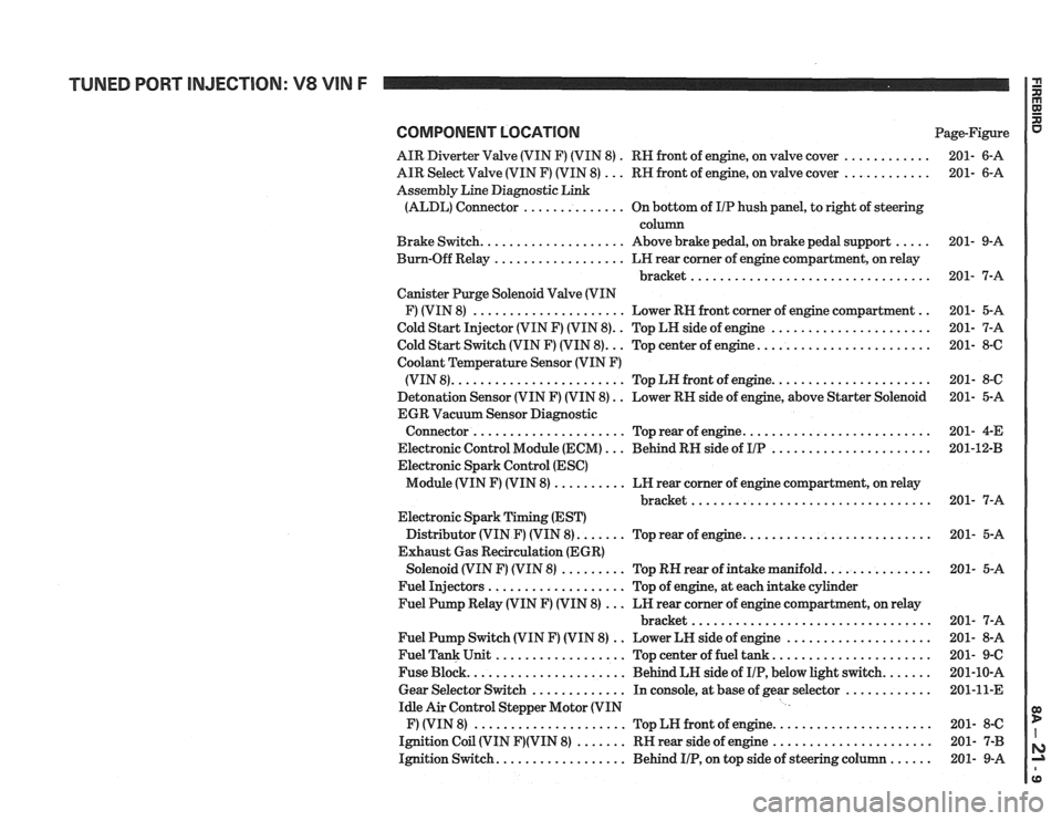
COMPONENT LOCATION Page-Figure
AIR Diverter Valve (VIN F) (VIN 8)
. RN front of engine, on valve cover ............ 201- 6-A
AIR Select Valve (VIN F) (VIN 8)
... RN front of engine, on valve cover ............ 201- 6-A
Assembly Line Diagnostic Link
(ALDL) Connector
.............. On bottom of IIP hush panel, to right of steering
column
Brake Switch.
................... Above brake pedal, on brake pedal support ..... 201- 9-A
Bum-Off Relay
.................. LN rear comer of engine compartment, on relay
bracket
................................. 201- 7-A
Canister Purge Solenoid Valve (VIN
F) (VIN 8)
..................... Lower RN front corner of engine compartment .. 201- 5-A
Cold Start Injector (VIN F) (VIN 8).
. Top LH side of engine ...................... 201- 7-A
.. ....................... Cold Start Switch (VIN F) (VIN 8). Top center of engine. 201- 8-6
Coolant
Temperature Sensor (VIN F)
..................... (VIN 8). ....................... Top LN front of engine. 201- 8-C
Detonation Sensor (VIN F) (VIN 8)
. . Lower RN side of engine, above Starter Solenoid 201- 5-A
EGR Vacuum Sensor Diagnostic
......................... Connector ..................... Top rear of engine. 201-
4-E
Electronic Control Module (ECM)
... Behind RN side of IIP ...................... 201-1243
Electronic Spark Control (ESC)
Module (VIN F) (VIN 8)
.......... LN rear corner of engine compartment, on relay
............................... bracket.. 201- 7-A
Electronic Spark Timing (EST)
Distributor (VIN
F) (VIN 8). ...... Top rear of engine. ......................... 201- 5-A
Exhaust Gas Recirculation (EGR)
Solenoid (VIN
F) (VIN 8) ......... Top RN rear of intake manifold. .............. 201- 5-A
Fuel Injectors
................... Top of engine, at each intake cylinder
Fuel Pump Relay (VIN
F) (VIN 8) ... LN rear corner of engine compartment, on relay
bracket
................................. 201- 7-A
Fuel Pump Switch (VIN
F) (VIN 8) .. Lower LN side of engine .................... 201- 8-A
Fuel Tank Unit
.................. Top center of fuel tank ...................... 201- 9-C
Fuse Block.
..................... Behind LH side of IIP, below light switch. ...... 201-10-A
Gear Selector Switch
............. In console, at base of gear selector ............ 201-11-E
Idle Air Control Stepper Motor (VIN
F) (VIN 8)
..................... Top LN front of engine. ..................... 201- 8-C
Ignition Coil (VIN
F)(VIN 8) ....... RN rear side of engine ...................... 201- 7-B
Ignition Switch.
................. Behind IIP, on top side of steering column ...... 201- 9-A
Page 1277 of 1825
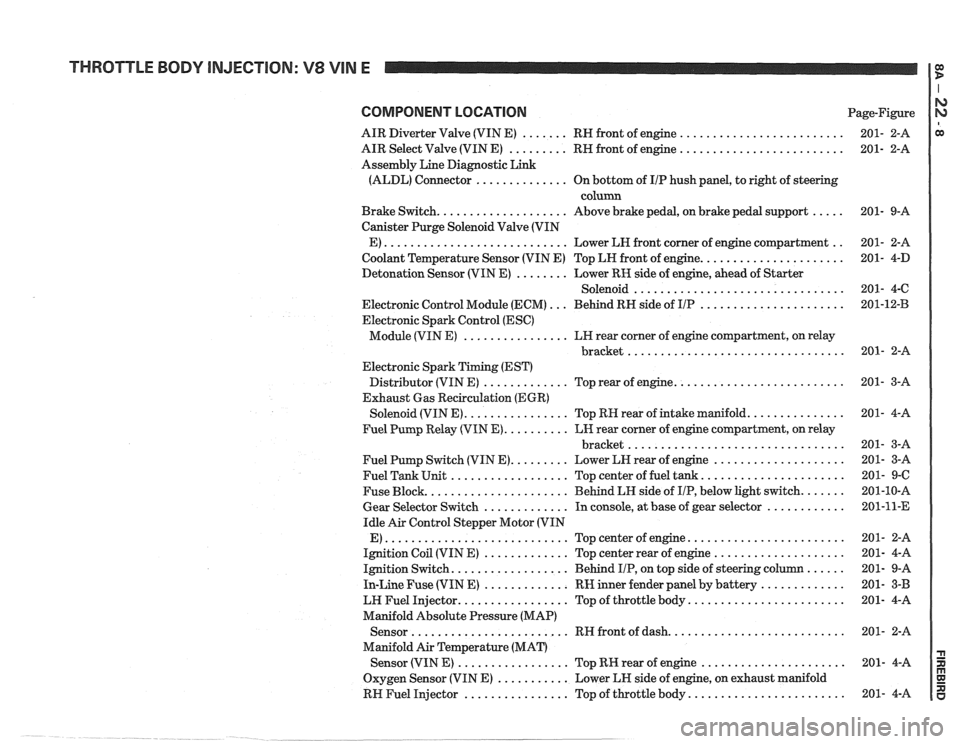
THROTTLE BODY INJECTION: V8 VIN E
COMPONENT LOCATION Page-Figure
AIR Diverter Valve (VIN E)
....... RH front of engine .........................
AIR Select Valve (VIN E) ......... RH front of engine .........................
Assembly Line Diagnostic Link
(ALDL) Connector
.............. On bottom of IIP hush panel, to right of steering
column
Brake Switch.
................... Above brake pedal, on brake pedal support .....
Canister Purge Solenoid Valve (VIN
E)
............................ Lower LH front corner of engine compartment ..
Coolant Temperature Sensor (VIN E) Top LH front of engine. .....................
Detonation Sensor (VIN E) ........ Lower RK side of engine, ahead of Starter
Solenoid
................................
Electronic Control Module (ECM) ... Behind RH side of IIP ......................
Electronic Spark Control (ESC)
Module (VIN E)
................ LH rear corner of engine compartment, on relay
................................. bracket
Electronic Spark Timing (EST)
Distributor (VIN E)
............. Top rear of engine. .........................
Exhaust Gas Recirculation (EGR)
Solenoid (VIN E).
............... Top RH rear of intake manifold. ..............
Fuel Pump Relay (VIN E). ......... LH rear corner of engine compartment, on relay
................................. bracket
Fuel Pump Switch (VIN E).
........ Lower LH rear of engine ....................
Fuel Tank Unit .................. Top center of fuel tank. .....................
Fuse Block. ..................... Behind LH side of IIP, below light switch. ......
Gear Selector Switch ............. In console, at base of gear selector ............
Idle Air Control Stepper Motor (VIN
E)
............................ Topcenterofengine ........................
Ignition Coil (VIN E) ............. Top center rear of engine ....................
Ignition Switch. ................. Behind IIP, on top side of steering column ......
In-Line Fuse (VIN E) ............. RW inner fender panel by battery .............
LW Fuel Injector. ................ Top of throttle body. .......................
Manifold Absolute Pressure (MAP)
Sensor
........................ RH front of dash. ..........................
Manifold Air Temperature (MAT)
Sensor (VIN
E) ................. Top RK rear of engine ......................
Oxygen Sensor (VIN E) ........... Lower LH side of engine, on exhaust manifold
RH Fuel Injector
................ Top of throttle body. .......................