1988 PONTIAC FIERO engine coolant
[x] Cancel search: engine coolantPage 1289 of 1825
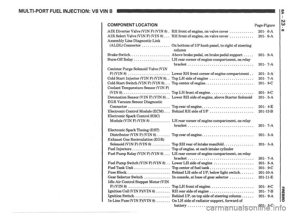
MULTI-PORT FUEL INJECTION: V8 VIN 8 It
COMPONENT LOCATION Page-Figure
. ............ AIR Diverter Valve (VIN F) (VIN 8)
RN front of engine. on valve cover 201- 6-A
............ AIR Select Valve (VIN F) (VIN 8) ... RW front of engine. on valve cover 201- 6-A
Assembly Line Diagnostic Link
(ALDL) Connector
.............. On bottom of I/P hush panel. to right of steering
column
..... Brake Switch .................... Above brake pedal. on brake pedal support 201- 9-A
Burn-Off Relay
.................. LH rear corner of engine compartment. on relay
bracket
................................. 201- 7-A
Canister Purge Solenoid Valve (VIN
.. F) (VIN 8) ..................... Lower RH front corner of engine compartment 201- 5-A'
.. ...................... Cold Start Injector (VIN F) (VIN 8) Top LH side of engine 201- 7-A
........................ Cold Start Switch (VIN F) (VIN 8) ... Top center of engine 201- 8-6
Coolant Temperature Sensor (VIN F)
...................... (VIN 8) ........................ Top LN front of engine 201- 8-C
Detonation Sensor (VIN F) (VIN 8)
. . Lower RN side of engine. above Starter Solenoid 201- 5-A
EGR Vacuum Sensor Diagnostic
.......................... Connector ..................... Top rear of engine 201- 4-E
...................... Electronic Control Module (ECM) ... Behind RH side of IIP 201-12-B
Electronic Spark Control (ESC)
Module (VIN F) (VIN 8)
.......... LH rear corner of engine compartment. on relay
bracket
................................. 201- 7-A
Electronic Spark Timing (EST)
.......................... Distributor (VIN F) (VIN 8) ....... Top rear of engine 201- 5-A
Exhaust Gas Recirculation (EGR)
............... Solenoid (VIN F) (VIN 8) ......... Top RN rear of intake manifold 201- 5-A
Fuel Injectors
................... Top of engine. at each intake cylinder
Fuel Pump Relay (VIN F) (VIN 8)
... LH rear corner of engine compartment. on relay
bracket
................................. 201- 7-A
.. ................... Fuel Pump Switch (VIN F) (VIN 8)
Lower LH side of engine : 201- 8-A
...................... Fuel Tank Unit .................. Top center of fuel tank 201- 9-C
....... Fuse Block ...................... Behind LH side of IIP. below light switch 201-10-A
............ Gear Selector Switch ............. In console. at base of gear selector 201-11-E
Idle Air Control Stepper Motor (VIN
...................... F) (VIN 8) ..................... Top LN front of engine 201- 8-C
...................... Ignition Coil (VIN F)(VIN 8) ....... RH rear side of engine 201- 7-B
...... Ignition Switch .................. Behind IIP. on top side of steering column 201- 9-A
In-Line Fuse (VIN F)(VIN 8) ....... On LH side of radiator support. forward of
battery
................................. 201- 5-C
Page 1303 of 1825
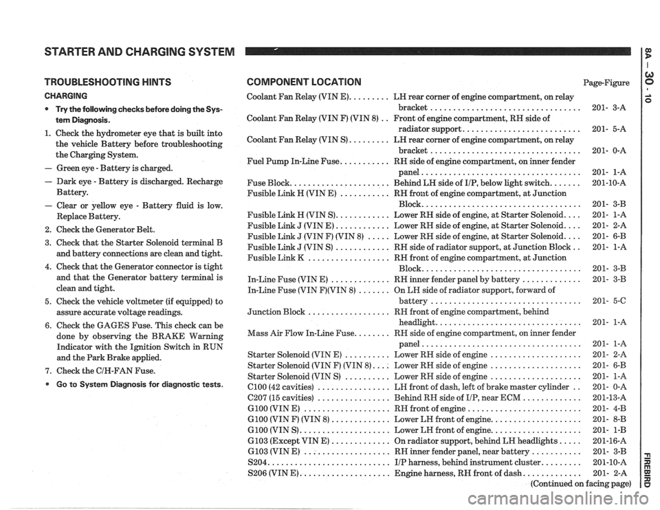
STARTER AND CHARGING SYSTEM
TROUBLESHOOTING HINTS
CHARGING
* Try the following checks before doing the Sys-
tem Diagnosis
.
1 . Check the hydrometer eye that is built into
the vehicle Battery before troubleshooting
the Charging System
.
- Green eye . Battery is charged .
. Dark eye . Battery is discharged . Recharge
Battery
.
- Clear or yellow eye . Battery fluid is low .
Replace Battery .
2 . Check the Generator Belt .
3 . Check that the Starter Solenoid terminal B
and battery connections are clean and tight
.
4 . Check that the Generator connector is tight
and that the Generator battery terminal is
clean and tight
.
5 . Check the vehicle voltmeter (if equipped) to
assure accurate voltage readings
.
6 . Check the GAGES Fuse . This check can be
done by observing the BRAKE Warning
Indicator with the Ignition Switch in RUN
and the Park Brake applied
.
7 . Check the GIN-FAN Fuse .
Go to System Diagnosis for diagnostic tests .
COMPONENT LOCATION Page-Figure
Coolant Fan Relay (VIN
E) ......... LH rear corner of engine compartment. on relay
bracket
................................. 201- 3-A
Coolant Fan Relay (VIN F) (VIN 8)
. . Front of engine compartment. RH side of
radiator support
.......................... 201- 5-A
Coolant Fan Relay (VIN S)
......... LN rear corner of engine compartment. on relay
bracket
................................. 201- 0-A
Fuel Pump In-Line Fuse
........... RH side of engine compartment. on inner fender
panel
................................... 201- 1-A
Fuse Block
...................... Behind LN side of IIP. below light switch ....... 201-10-A
Fusible Link H (VIN E)
........... RH front of engine compartment. at Junction
................................... Block 201- 3-B
Fusible Link
H (VIN S) ............ Lower RN side of engine. at Starter Solenoid .... 201- 1-A
Fusible Link
J (VIN E) ............ Lower RH side of engine. at Starter Solenoid .... 201- 2-A
Fusible Link
J (VIN F) (VIN 8) ..... Lower RH side of engine. at Starter Solenoid .... 201- 6-B
Fusible Link
J (VIN S) ............ RH side of radiator support. at Junction Block .. 201- 1-A
Fusible Link
K .................. RH front of engine compartment. at Junction
................................... Block 201- 3-B
In-Line Fuse (VIN E)
............. RH inner fender panel by battery ............. 201- 3-B
In-Line Fuse (VIN
F)(VIN 8) ....... On LH side of radiator support. forward of
................................. battery 201- 5-6
.................. Junction Block RH
front of engine compartment. behind
................................ headlight 201- 1-A
........ Mass Air Flow In-Line Fuse RR side of engine compartment. on inner fender
................................... panel 201- 1-A
Starter Solenoid (VIN E)
.......... Lower RH side of engine .................... 201- 2-A
Starter Solenoid (VIN F) (VIN
8) .... Lower RH side of engine .................... 201- 6-B
Starter Solenoid (VIN S)
.......... Lower RN side of engine .................... 201- 1-A
el00 (42 cavities) ................ LH front of dash. left of brake master cylinder .. 201- 0-A
C207 (15 cavities)
................ Behind RH side of IIP. near ECM ............. 201-13-A
G100 (VIN E) ................... RH front of engine ......................... 201- 4-B
G100 (VIN F) (VIN 8) ............. Lower LH front of engine .................... 201- 8-B
G100 (VIN S) .................... Lower LH front of engine .................... 201- 1-B
6103 (Except VIN E) ............. On radiator support. behind LH headlights ..... 201-16-A
6.103 (VIN E) ................... RH inner fender panel. near battery ........... 201- 3-B
S204
........................... IIP harness. behind instrument cluster ......... 201-10-A
S206 (VIN
E) .................... Engine harness. RH front of dash ............. 201- 2-A
(Continued on facing page)
Page 1309 of 1825
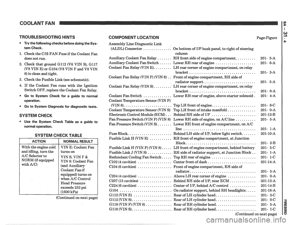
COOLANT FAN I g
TROUBLESHOOTING HINTS
@ Try the following checks before doing the Sys-
tem Check.
1. Check the CIH-FAN Fuse if the Coolant Fan
does not run.
2. Check that ground 6112 (V6 VIN S), 6117
(V8 VIN E) or 6104 (V8 VIN F and V8 VIN
8) is clean and tight.
3. Check the Fusible Link (see schematic).
4.
If the Coolant Fan runs with the Ignition
Switch OFF, replace the Coolant Fan Relay.
@ Go to System Check for a guide to normal
operation.
Go to System Diagnosis for diagnostic tests.
SYSTEM CHECK
Use the System Checlc Table as a guide to
normal operation.
SYSTEM CHECK TABLE
I ACTION I NORMALRESULT 1
COMPONENT LOCATION Page-Figure
Assembly Line Diagnostic Link
(ALDL) Connector .............. On bottom of IIP hush panel, to right of steering
column
Auxiliary Coolant Fan Relay
....... RH front side of engine compartment. ......... 201- 5-A
Auxiliary Coolant Fan Switch
...... Lower RN rear of engine .................... 201- 6-A
Coolant Fan Relay (VIN
E). ........ LH rear corner of engine compartment, on relay
bracket
................................. 201- 3-A
Coolant Fan Relay (VIN F) (VIN 8)
. . Front of engine compartment, RN side of
radiator support.
......................... 201- 5-A
Coolant Fan Relay (VIN S)
......... LH rear corner of engine compartment, on relay
................................. bracket 201- 0-A
Coolant Fan Switch
.............. Lower RH rear of engine, above starter solenoid . 201- 4-A
Coolant Temperature Sensor (VIN F)
(VIN 8).
....................... Top LW front of engine. ..................... 201- 8-C
Coolant Temperature Sensor (VIN S) Top LH front of intake manifold.
............. 201- 0-A
Electronic Control Module (ECM)
... Behind RN side of IIP ...................... 201-12-B
Fan Pressure Switch (VIN F) (VIN 8) Lower RH side of engine, on
AIC line .......... 201- 5-A
Fan Pressure Switch (VIN S)
....... Lower RN front of engine compartment, on AIC
line .................................... 201- 1-A
Fuse Block.
..................... Behind LN side of IIP, below light switch. ...... 201-10-A
Fusible Link
N (VIN E) ........... RH front of engine compartment, at Junction
Block ................................... 201- 3-B
Fusible Link N (VIN F) (VIN 8).
.... LN front of engine compartment, behind battery 201- 5-C
Fusible Link
J (VIN S) ............ RN side of radiator support, at Junction Block .. 201- 1-A
Redundant Cooling Fan Switch.
.... Top RW rear of engine ...................... 201- 1-6
C102 (4 cavities) ................. Center front of dash. ....................... 201-14-A
6104 (6 cavities)
................. Front of engine compartment, RH side of
................................ radiator. 201- 5-A
C204 (4 cavities) ................. Above LH rear corner of engine .............. 201- 0-A
C207 (15 cavities)
................ Behind RH side of IIP, near ECM ............. ,201-13-A
C224 (6 cavities) ................. Center of IIP, behind AIC control ............. 201-14-B
6104
.......................... On radiator support, behind RN headlights. .... 201-16-A
6112 (VIN E)
................... Rear of LN cylinder head. ................... 201- 3-C
6112 (VIN S)
.................... Rear of LH cylinder head. ................... 201- 0-C
6118 (VIN F) (VIN 8)
............. Rear of RH cylinder head. ................... 201- 5-A
6118 (VIN S)
.................... Rear of RH cylinder head. ................... 201- 1-C
(Continued on next page)
With
the engine cold
and idling, turn the
AIC Selector to
NORM (if equipped
with Ale)
VIN E: Coolant Fan
turns on
VIN S, VIN
F &
VIN 8: Coolant Fan
(and Auxiliary
Coolant Fan-if
equipped) turns on
when
A/C Control
Head Pressure
exceeds 233 psi
(1600
kPa)
(Continued on next page)
Page 1310 of 1825
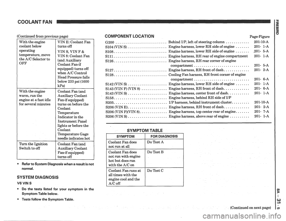
COOLANT FAN
With the engine
warm, run the
engine at a fast idle
for several minutes
(Continued
from previous page)
Switch to off
With
the engine
coolant below
operating
temperature, move
the AlC Selector to
OFF
Coolant Fan (and
Auxiliary Coolant
Fan-if equipped)
turns on before the
Coolant
Temperature
Indicator in the
Instrument Panel
lights or before the
Coolant
Temperature Gage
needle indicates hot
Coolant Fan (and
Auxiliary Coolant
Fan-if equipped)
turns off
VIN E:
Coolant Fan
turns off
VIN S, VIN F
&
VIN 8: coolant Fan
(and ~~~ili~~~
Coolant Fan-if
equipped) turns off
when
A/C Control
Head Pressure falls
below 233 psi (1600
kPa)
- -
* Refer to System Diagnosis when a result is not
normal.
SYSTEM DIAGNOSIS
V6 VIN S
* Do the tests listed for your symptom in the
Symptom Table below.
@ Tests follow the Symptom Table.
COMPONENT LOCATION Page-Figure
.......................... ............ 6-200 Behind IIP, left of steering column 201-10-A
....... .................... S104 (VIN S) Engine harness,
lower RN side of engine 201- l-A
....... .......................... S108. Engine harness, lower RN side of engine .201- 5-A
........................... S111 Engine harness, RR rear of engine compartment 201- l-A
.......................... S126. Engine harness, RR rear corner of engine
............................ compartment 201- 5-A
.......................... ............ S127. Engine harness, RH front of dash. 201- 2-A
.......................... S128. Cooling Fan harness, RN front corner of engine
............................ compartment 201- 6-A
.................... S142 (VIN S) Engine harness, lower RR side of engine ....... 201- l-A
............ S143 (VIN F) (VIN 8) ............. Engine harness, RH front of dash. 201- 6-A
.................... S143 (VIN S) Engine
harness, center front of dash. .......... 201- l-A
.......................... S158. Engine harness, behind RH side of IIP
.......................... S205. I/P harness, behind instrument cluster. ........ 201-10-A
S206 (VIN E)
.................... Engine harness, RH front of dash. ............ 201- 2-A
S206 (VIN
F)(VIN 8). ............. Engine harness, top center rear of engine. ...... 201- 7-A
.................... S206 (VIN S) Engine harness, above rear of engine .......... 201- 1-A
SYMPTOM TABLE
all times with the
engine cool and the
SYMPTOM
Coolant Fan does
not
run at all
Coolant Fan does
not run with engine
hot but does
run
with the A/C on
(Continued on next page)
FOR DIAGNOSIS
Do Test A
Do Test B
Page 1312 of 1825
COOLANT FAN rn
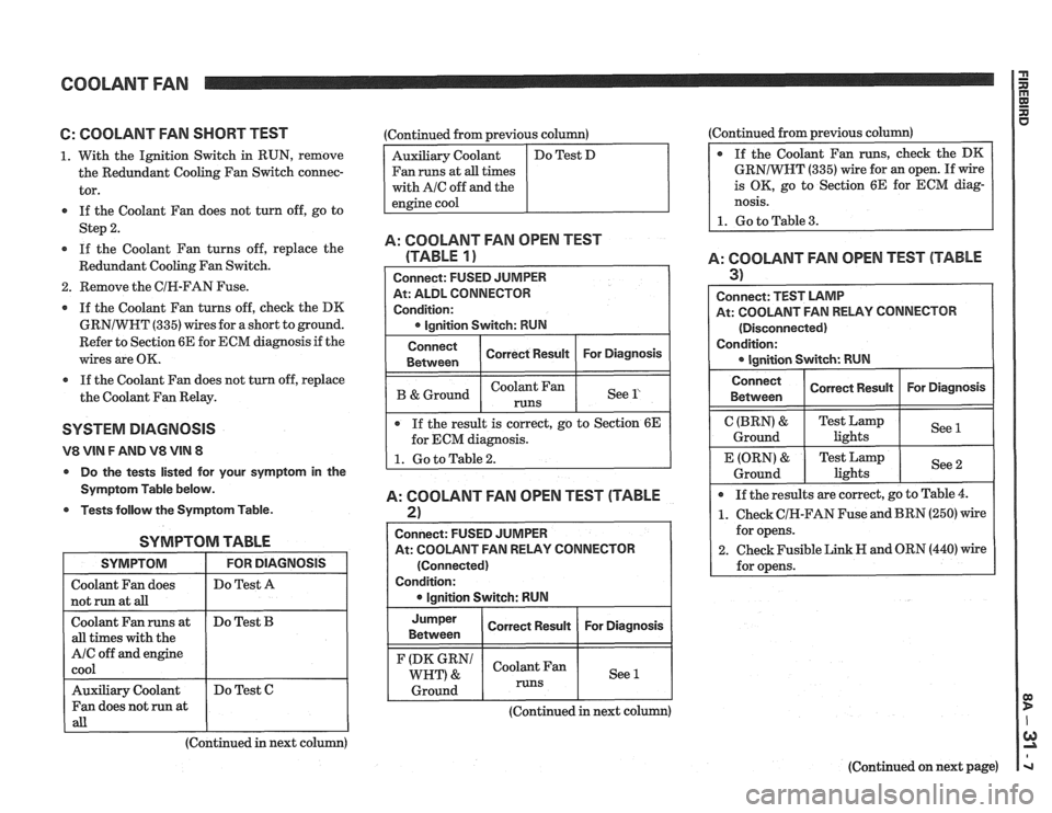
6: COOLANT FAN SHORT TEST
1. With the Ignition Switch in RUN, remove
the Redundant Cooling Fan Switch connec-
tor.
If the Coolant Fan does not turn off, go to
Step
2.
If the Coolant Fan turns off, replace the
Redundant Cooling Fan Switch.
2. Remove the CIR-FAN Fuse.
If the Coolant Fan turns off, check the DK
GRNIWHT
(335) wires for a short to ground.
Refer to Section 6E for ECM diagnosis if the
wires are OK.
a If the Coolant Fan does not turn off, replace
the Coolant Fan Relay.
SYSTEM DlAGNOSlS
V8 VIN F AND V8 VIN 8
Do the tests listed for your symptom in the
Symptom Table below.
Tests follow the Symptom Table.
SYMPTOM TABLE
I SYMPTOM I FORDIAGNOSIS I
I Do Test A I
I not run at aB I I
Coolant Fan runs at
all times with the
A/C off and engine
cool
(Continued in next column)
Do
Test
B
Auxiliary Coolant
Fan does not run at
all
:Continued from previous column)
Fan runs at
all times
with
AIC off and the
Do Test C (Continued
from previous column)
GRNIWNT
(335) wire for an open. If wire
is OK, go to Section 6E for ECM diag-
nosis.
1. Go to Table 3.
A: COOLANT FAN OPEN TEST
(TABLE
1)
At: ALDL CONNECTOR
Condition:
I B &Ground I I See l' I
Connect
Between
If the result is correct, go to Section 6E
for ECM diagnosis.
A: COOLANT FAN OPEN TEST (TABLE
2)
Correct Result
I
Connect: FUSED JUMPER
At: COOLANT FAN RELAY CONNECTOR For
Diagnosis
(Connected)
Condition: lgnition Switch: RUN
Jumper
I Correct Result I For Diagnosis I Between
(DK GRN1 Coolant Fan
WHT) & See 1
1 Ground 1 runs 1 1
A: COOLANT FAN OPEN TEST (TABLE
3) I
Connect: TEST LAMP
At: COOLANT FAN RELAY CONNECTOR
(Disconnected)
Condition:
Connect I Correct Rewn I For Diagnosis I I Between
C (BRN) &
Ground
If the results are correct, go to Table
4.
1. Check CIH-FAN Fuse and BRN (250) wire
for opens.
2. Check Fusible Link H and ORN (440) wire
for opens.
E (ORN)
&
Ground
(Continued in next column)
(Continued on next page)
Test Lamp
lights See
1
Test
Lamp
lights See 2
Page 1359 of 1825
AIR CONDITIONING: COMPRESSOR CONTROLS OD D
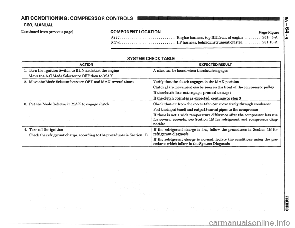
C60. MANUAL I I
(Continued from previous page) COMPONENT LOCATION
.......................... $177. Engine harness,
top RN front of engine ........ 201- 5-A
.......................... $204. I/P harness, behind instrument cluster. ........ 201-10-A
SYSTEM CHECK TABLE
I ACTION I EXPECTED RESULT I
1. Turn the Ignition Switch to RUN and start the engine A click can be heard when the clutch engages
Move the
A/C Mode Selector to OFF then to MAX
2. Move the Mode Selector between OFF and MAX several times Verify
that the clutch engages in the MAX position
I I Clutch plate movement can be seen on the front of the comgressor pdey I
I I If the clutch does not engage, proceed to step 4
If the clutch operates as expected, continue to step
3
3.
Put the Mode Selector in MAX to engage clutch Check
that air from the coolant fan can move freely through condensor
1 1 Feel the input (cool) and output (warm) pipes to the cornpressor I
I
If there is not a wide temperature difference after the compressor has run
for several seconds, see Section 1B for refrigerant and compressor diag-
nostics
4. Turn off the ignition If the
refrigerant charge is low, follow the procedures in Section 1B for
Check the refrigerant charge, according to the procedures in Section
1B refrigerant diagnosis
If the refrigerant charge is normal, isolate the conations using the pro-
cedures which follow in the System Diagnosis
Page 1367 of 1825
AIR CORIDI"F0NING: AIR DELIVERY
C60, MANUAL
(Continued from previous page)
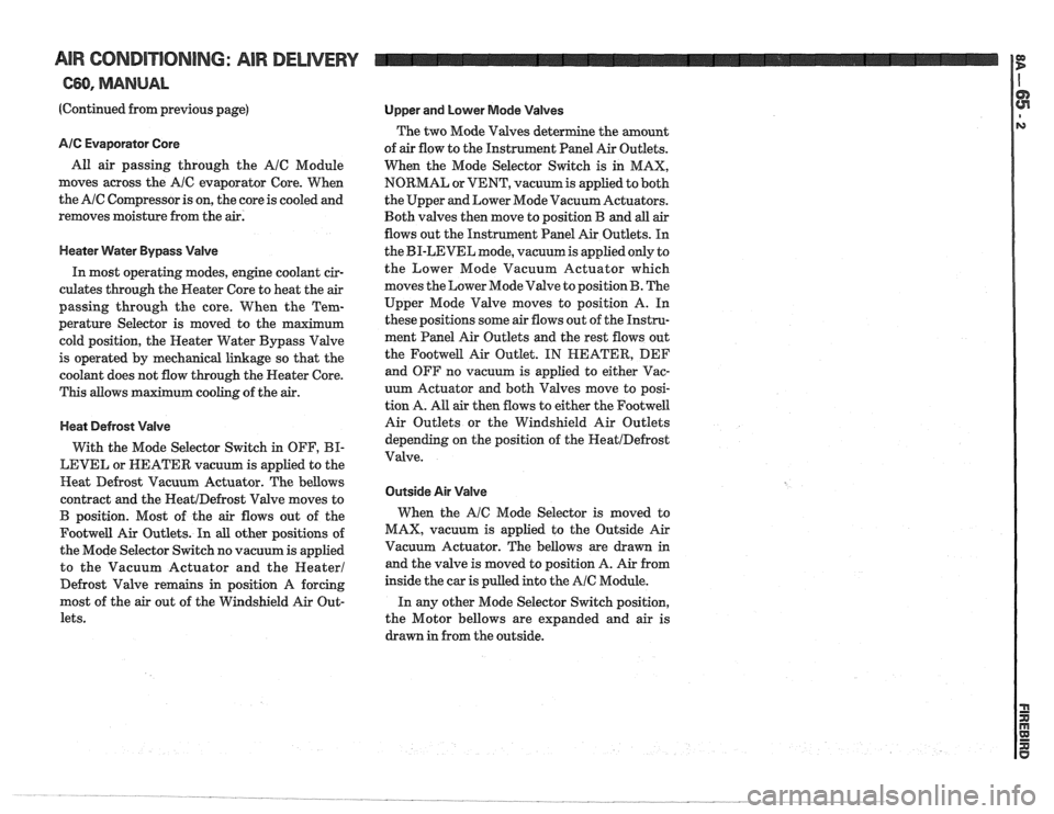
AIC Evaporator Core
All air passing through the AIC Module
moves across the
A/C evaporator Core. When
the
AIC Compressor is on, the core is cooled and
removes moisture from the air.
Heater Water Bypass Valve
In most operating modes, engine coolant cir-
culates through the Heater Core to heat the
air
passing through the core. When the Tem-
perature Selector is moved to the maximum
cold position, the Heater Water Bypass Valve
is operated by mechanical linkage so that the
coolant does not flow through the Neater Core.
This allows maximum cooling of the
air.
Heat Defrost Valve
With the Mode Selector Switch in OFF, BI-
LEVEL or NEATER vacuum is applied to the
Heat Defrost Vacuum Actuator. The bellows
contract and the
HeatIDefrost Valve moves to
B position. Most of the air flows out of the
Footwell Air Outlets. In all other positions of
the Mode Selector Switch no vacuum is applied
to the Vacuum Actuator and the
Heater1
Defrost Valve remains in position A forcing
most of the
air out of the Windshield Air Out-
lets.
Upper and Lower Mode Valves
The two Mode Valves determine the amount
of
air flow to the Instrument Panel Air Outlets.
When the Mode Selector Switch is in MAX,
NORMAL or VENT, vacuum is applied to both
the Upper and Lower Mode Vacuum Actuators.
Both valves then move to position B and
all air
flows out the Instrument Panel Air Outlets. In
the BI-LEVEL mode, vacuum is applied only to
the Lower Mode Vacuum Actuator which
moves the Lower Mode Valve to position
B. The
Upper Mode Valve moves to position A. In
these positions some air flows out of the Instru-
ment Panel Air Outlets and the rest flows out
the
Footwell Air Outlet. IN HEATER, DEF
and OFF no vacuum is applied to either Vac-
uum Actuator and both
Valves move to posi-
tion A. All
air then flows to either the Footwell
Air Outlets or the Windshield Air Outlets
depending on the position of the
HeatIDefrost
Valve.
Outside Air Valve
When the AIC Mode Selector is moved to
MAX, vacuum is applied to the Outside Air
Vacuum Actuator. The bellows are drawn in
and the valve is moved to position A. Air from
inside the car is pulled into the
AIC Module.
In any other Mode Selector Switch position,
the Motor bellows are expanded and air is
drawn in from the outside.
Page 1381 of 1825
AIR CONDITIONING: COMPRESSOR CONTROLS
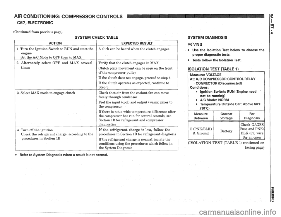
667, ELECTRONIC:
(Continued from previous page)
SYSTEM CHECK TABLE SYSTEM DIAGNOSIS
times
ACTION
1. Turn the Ignition Switch to RUN and start the
engine
Set the
A/C Mode to OFF then to MAX
2. Alternately select OFF and MAX several
Clutch plate movement can be seen on the front
1 ISOLATION TEST (TABLE I) of the compressor pulley
1 I If the clutch does not engage, proceed to step 4 (
EXPECTED RESULT
A click can be heard when the clutch engages
Verify that the clutch engages in MAX
If the clutch operates as expected, continue to
1 St€??J 3 I
V6 VIN S
r Use the isolation Test below to choose the
proper diagnostic tests.
Tests follow the isolation Test.
3. Select MAX mode to engage clutch Check
that air from the coolant fan can move
freely through condensor
Feel the input (cool) and output (warm) pipes to
the compressor
If there is not a wide temperature difference after
the compressor has run for several seconds, see
Section
1B for refrigerant and Compressor
diagnostics
4. Turn off the ignition
Check the refrigerant charge, according to the
procedures in Section
1B
If the refrigeramt charge is low, follow the
procedures in Section
1B for refrigerant diagnosis
If the refrigerant charge is normal, isolate the
conditions using the procedures which follow in
the System Diagnosis
(ISOLATION TEST (TABLE 1) continued on
facing page)
Measure: VOLTAGE
At: AIC COMPRESSOR CONTROL RELAY
CONNECTOR (Disconnected)
Conditions:
ignition Switch: RUN (Engine need
not
be running)
c A/@ Mode: NORM
* Temperature Outside Car: Above 60°F
(16°C)
Refer to System Diagnosis when a result is not normal. Measure
Between
C (PNKIBLK)
& Ground
Correct
Voltage
Battery
For
Diagnosis
Check GAGES
Fuse and PNKi
BLK (39) wire
for an open