1988 PONTIAC FIERO engine coolant
[x] Cancel search: engine coolantPage 1436 of 1825
DRIVER INFORMATION CENTER (DIC)
(Continued from facing page)
@ If both tests are good, replace the Washer
Fluid Level Switch.
1. Check the BLKIWHT (99) wire for an
open (see schematic).
2. Check the BLK (152) wire for an open (see
schematic).
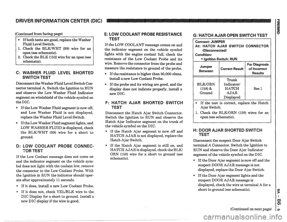
6: WASHER FLUID LEVEL SHORTED
SwlTen TEST
Disconnect the Washer Fluid Level Switch Con-
nector
terminal A. Switch the Ignition to RUN
and observe the Low Washer Fluid Indicator
segment on windshield of the vehicle symbol on
the
me.
If the Low Washer Fluid segment is now off,
and Low Washer Fluid is not displayed,
replace the Washer Fluid Level Switch.
If the Low Washer Fluid segment lights, and
LOW
VirASHER FLUID is displayed, check
the
BLKIWWT (99) wire for a short to
ground.
B: LOW COOLANT PROBE CONNEC-
TOR TEST
If the Low Coolant message does not come on
and the indicator segment on the vehicle sym-
bol does not light with the coolant low, remove
the connector to the Low Coolant Probe. With
the Ignition in RUN the indicator
should oper-
ate after approximately
11 seconds.
If it does,
install a new Low Coolant Probe.
* If it does not, check YELIBLM wire to the
DIC Display for a short to ground. Install a
new DIC display if the wire is good.
E: LOW COOLANT PROBE RESISTANCE
TEST
If the LOW COOLANT message comes on and
the indicator segment on the vehicle symbol
lights with the engine coolant full, check the
resistance of the Low Coolant Probe and its
wire. Remove the connector from the probe and
measure the resistance to ground of the probe.
If the resistance is higher than 30,000 ohms,
instdl a new Low Coolant Probe.
If the probe
and its wiring are good, and the
display does not indicate properly, install a
new DIC.
F: HATCH AJAR SHORTED SWITCH
TEST
Disconnect the Hatch Ajar Switch Connector.
Switch the Ignition to RUN and observe the
Hatch Ajar Indicator segment on the trunk of
the vehicle symbol on the DIC.
If the Hatch Ajar segment is now off and
HATCH AJAR is not displayed, replace the
Hatch Ajar Switch.
o If the Hatch Ajar segment is still on, and
HATCH AJAR is displayed, check the
BLKl
ORN (158) wire for a short to ground (see
schematic).
6: WATCH AJAR OPEN SWITCH TEST
R SWITCH CONNECTOR
1. Check the BEKIORN (158) wires for an
open (see schematic).
)-I: BOOR AJAR SHORTED SWITCH
TEST
Disconnect the suspect Door Ajar Switch
a1 A Connector. Switch the Ignition to
RUN and observe the Door Ajar
Indieator
segment of the vehicle symbol on the DIC.
@ If the Door Ajar segment is now off and the
suspect DOOR AJAR message is not
displayed, replace the Door Ajar Switch.
If the Door Ajar segment lights and the
suspect DOOR
AJAR message is
displayed, check the wire at
terminal A for a
short to ground (see schematic).
(Continued on next page)
Page 1437 of 1825
DRIVER INFORMATION CENTER (DIC) I $
(Continued from previous page)
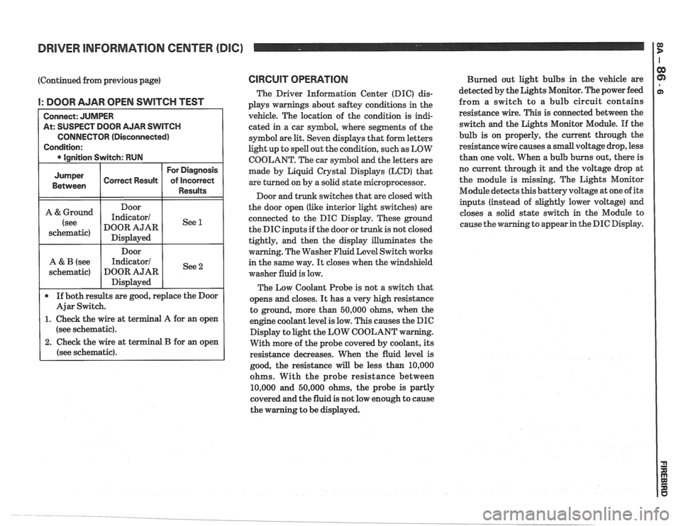
I: DOOR AJAR OPEN SWITCH TEST
At: SUSPECT DOOR AJAR SWITCH
CONNECTOR (Disconnected)
(see schematic).
2. Check the wire at terminal B for an open
(see schematic).
CIRCUIT OPERATION
The Driver Information Center (DIC) dis-
plays warnings about
saftey conditions in the
vehicle. The location of the condition is indi-
cated in a car symbol, where segments of the
symbol are
lit. Seven displays that form letters
light up to spell out the condition, such as LOW
COOLANT. The car symbol and the letters are
made by Liquid
Crystal Displays (LCD) that
are turned on by a solid state microprocessor.
Door and trunk switches that are closed with
the door open (like interior light switches) are
connected to the DIC Display. These ground
the DIC inputs if the door or trunk is not closed
tightly, and then the display illuminates the
warning. The Washer Fluid Level Switch works
in the same way.
It closes when the windshield
washer fluid is low.
The Low Coolant Probe is not a switch that
opens and closes.
It has a very high resistance
to ground, more than 50,000 ohms, when the
engine coolant level is low. This causes the DIC
Display to light the LOW COOLANT w
With more of the probe covered by coolant, its
resistance decreases. When the fluid level is
good, the resistance
will be less than 10,000
ohms. With the probe resistance between
10,000 and 50,000 ohms, the probe is partly
covered and the fluid is not low enough to cause
the warning to be displayed. Burned
out light bulbs in the vehicle are
detected by the Lights Monitor. The power feed
from a switch to a bulb circuit contains
resistance wire. This is connected between the
switch and the Lights Monitor Module.
If the
bulb is on properly, the current through the
resistance wire causes a small voltage drop, less
than one volt. When a bulb burns out, there is
no current through it
and the voltage drop at
the module is missing. The Lights Monitor
Module detects this battery voltage at one of its
inputs (instead of slightly lower voltage) and
closes a solid state switch in the Module to
g to appear in the DIC Display.
Page 1566 of 1825
COMPONENT LOCATION VIEWS
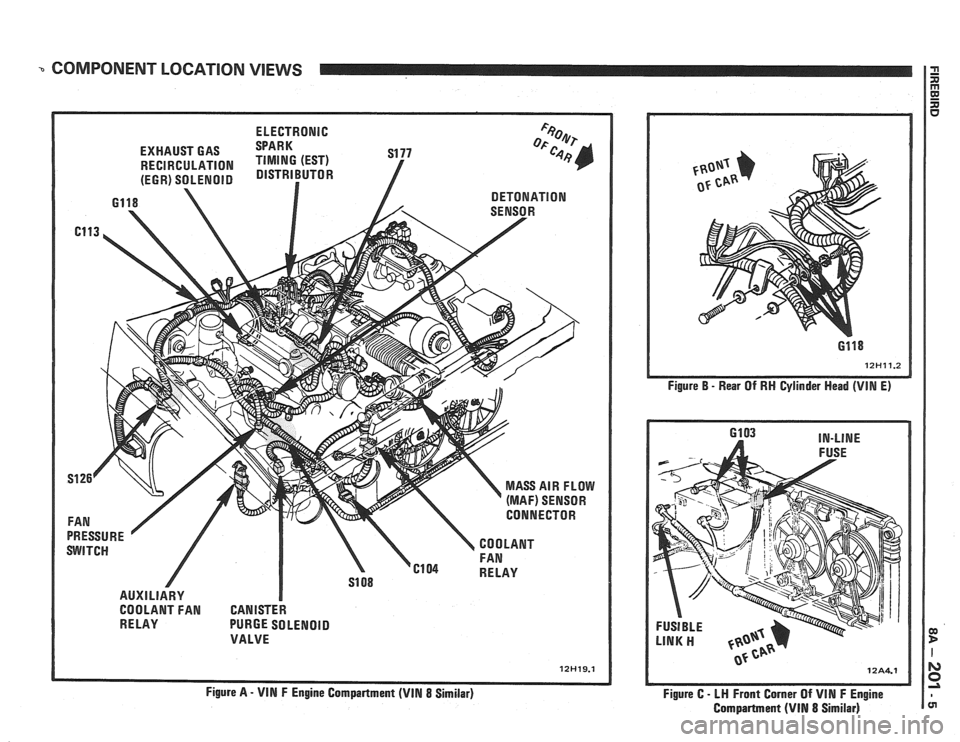
ELECTRONIC
EXHAUST GAS
~~~~ S177
RECIRCULATION
(EGR) SOLENOID
AUXILIARY I
COOLANT FAN CANISTER
RELAY PURGE SOLENOID
VALVE
Figure
A - VIN F Engine Compartment (VIN 8 Similar) Figure
B - Rear
Of RH Cylinder Head (VIN E)
6103 IN-LINE
Figure C
- LW Front Corner Of VIN F Engine
Compartment
(VIM 8 Similar)
Page 1567 of 1825
3 COMPONENT LOCATIQN VIEWS ca D
l
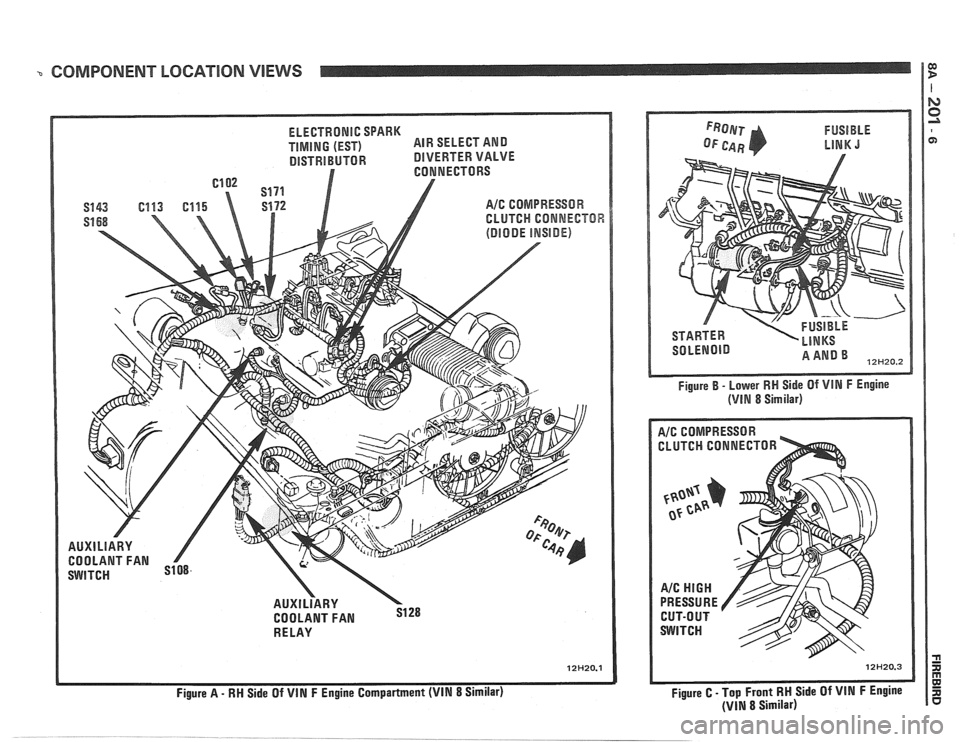
ELECTRONIC SPARK
TIMING (EST) AIR
SELECT AND
DISTRIBUTOR DlVERTER VALVE
A/C COMPRESSOR
CLUTCH
CONNECTOR
AUXlLlARY
COOLANT FAN
RE LAY
Figure
A - RM Side Of VIN F Engine Compartment (VIN 8 Similar) Figure
B - Lower
RW Side Of VIN F Engine
(VlN 8 Similar)
A/C COMPRESSOR -
CLUTCH CONNECTOR
I
Figure C - Top Front RM Side Of VIN F Engine
(VIN 8 Similar)
Page 1569 of 1825
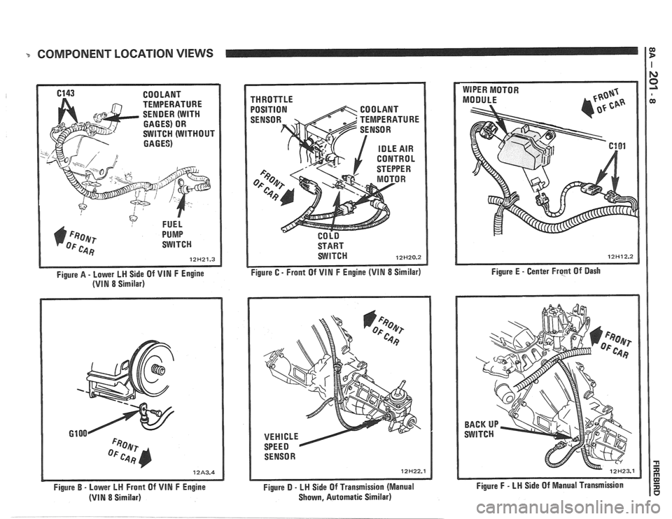
COMPONENT LOCATION VIEWS I $
6143 COOLANT
TEMPERATURE
SENDER (WITH
GAGES) OR
SWITCH (WITHOUT
GAGES)
FUEL
1) F~oer PUMP
OF c.4 Fj SWITCH
12H21.3
Figure A - Lower LH Side Of VIN F Engine
(VIN 8 Similar)
Figure
B - Lower LH Front Of VIN F Engine
(VIN 8 Similar) THROTTLE
POSITION
START
WITCH 12H20.2
Figure C - Front Of VIN F Engine (VIM 8 Similar)
SENSOR
12H22.1
Figure D - LH Side Of Transmission (Manual
Shown, Automatic Similar) Figure
E
- Center Frcpt Of Dash
Figure
F - LN Side Of Manual Transmission
Page 1614 of 1825
INSTRUMENT PANEL. GAGES & CONSOLE 8C-3
tank only when ignition switch is turned to "ON" or
"ACCESSORY" positions.
When ignition is turned to "OFF" or "START"
positions, the pointer may come to rest at any position.
The letters
"E" and "F" on the fuel gage are used to
point out direction of indicator travel only.
TEMPERATURE WARNING LIGHT
The engine temperature warning light is
controlled by a thermal switch which senses engine
coolant temperatures.
When the ignition switch is turned to "START"
position, a test circuit is closed and the light will come
on to indicate whether the light is functioning properly.
It is important to note that with low boiling-point
coolants (such as plain water) the temperature light
may not come on even though the coolant is boiling.
GENERATOR WARNING LIGHT
The generator warning light, located in the
instrument cluster, should come on when the ignition
switch is turned
"ON" and engine is not running. If
not, either the bulb is burned out or wiring to generator
has an open circuit.
When the generator voltage output becomes
greater than the battery voltage, the
"GEN" light
should go out. This does not, however, indicate
whether the battery is being charged or if the voltage
regulator is functioning properly.
Checks of the charging system are covered in
Section 6D, 'Engine Electrical'.
ENGINE OIL PRESSURE LIGHT
The engine oil pressure warning light is mounted
in the instrument cluster and controlled by a pressure
operated switch located on the engine block. When the ignition switch is
in the
"run" or "start9' position, the
oil pressure light should come on. If not, the bulb is
burned out, there is an open circuit between the bulb
and the oil pressure switch, or there is an open circuit
between the oil pressure switch and the choke heater.
After the engine is running, the oil pressure light
should go out when the oil pressure reaches the correct
specification. If not an oil pressure problem, a faulty oil
pressure switch or an open circuit from the choke
heater fuse to the oil pressure switch is indicated.
"SERVICE ENGINE SOON" LIGHT
All cars have a "SERVICE ENGINE SOON"
light mounted in the instrument cluster. The
"SERVICE ENGINE SOON9' light should come on
during engine starting. The light may stay on
a short
time after the engine starts.
If the light comes on while
driving, service to the emission control system may be
required. See Section
6E and Section 8A-80,
'Instrument Cluster', for complete diagnosis and
wiring diagrams of the
""P;RVICE ENGINE SOON"
light circuit.
UPSHIFT INDICATOR LIGHT
If your vehicle has a manual transmission, there
may be an
''Upshift" light on the instrument panel.
This light is illuminated to indicate optimum shift
points throughout the range from optimum fuel
economy to optimum performance. When this light is
on, shift your transmission to the next higher gear
range if conditions permit. For fuel economy,
accelerate slowly and shift when the light goes on. For
performance, accelerate as desired and shift when the
light goes on.
Safe operation of the vehicle may require shifting
differently than indicated by the "Upshift" light to
adapt to weather, road or traffic conditions.
Downshifting one or more gears may be required
to keep the engine running smoothly or to maintain
satisfactory performance.
DIAGNOSIS
Diagnostic information for all instrument panel
electrical systems is found in Section
8A-80,
'Instrument Panel'.
CAUTION: When removing or
installing any electrical units,
disconnect the negative battery cable
to prevent possible short circuits
which could lead to personal injury
and/or property damage. When
replacing a speedometer or
odometer assembly, the law requires the
odometer reading of the replacement unit to
be set to register the same mileage as the
prior odometer.
if the same mileage cannot be
set, the
law requires that the replacement
odometer be set to zero and a label be
installed on the driver's door frame to show
the previous odometer reading and the date
of replacement.
GENERAL BNFORMATlOM
INSTRUMENT PANEL AND GAGES
The instrument panel is a single unit design and
and screws. To service the instrument panel and
all parts attach to the main instrument panel with clips components see Figs. 601 through 610.
Page 1819 of 1825
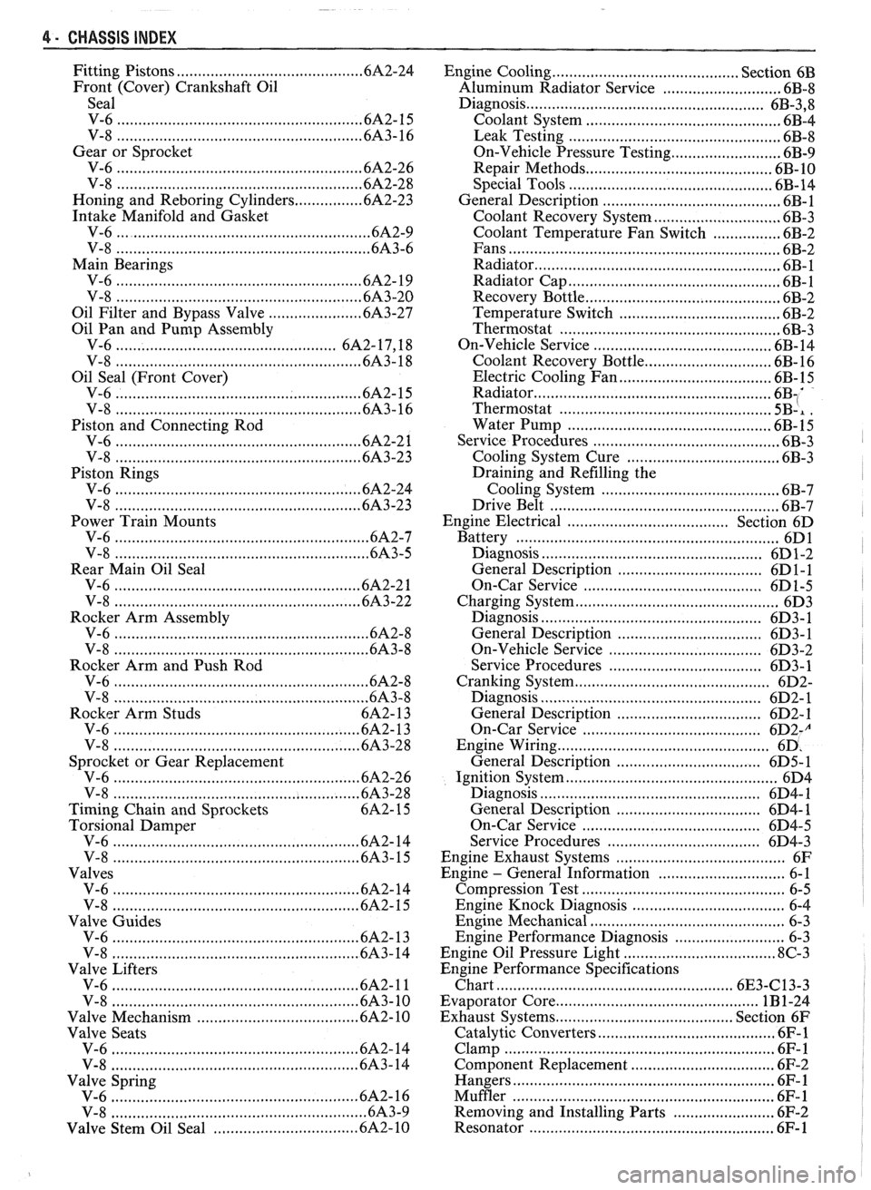
4 . CHASSIS INDEX
Fitting Pistons ......................................... .6A 2.24
Front (Cover) Crankshaft Oil
Seal
V-6
......................................................... 6A2- 15
V-8
................................................... 6A3- 16
Gear or Sprocket
V-6
......................................................... .6A 2.26
V-8
........................................................ 6A2-28
Honing and Reboring Cylinders ................ 6A2-23
Intake Manifold and Gasket
V-6
......................................................... .6A 2.9
V-8
............................................................ 6A3-6
Main Bearings
V-6
......................................................... .6A 2. 19
V-8
.......................................................... 6A3-20
Oil Filter and Bypass Valve
...................... 6A3-27
Oil Pan and Pump Assembly
V-6
................................................. 6A2.17, 18
V-8
......................................................... 6A3- 18
Oil Seal (Front Cover)
V-6
......................................................... 6A2- 15
V-8 .......................................................... 6A3-16
Piston and Connecting Rod
V-6
......................................................... .6A 2.2 1
V-8
....................................................... .6A 3.23
Piston Rings V-6
......................................................... .6A 2.24
V-8
........................................................ .6A 3.23
Power Train Mounts
V-6
........................................................... .6A 2.7
V-8
.......................................................... 6A3-5
Rear Main Oil Seal
V-6
......................................................... .6A 2.2 1
V-8 ......................................................... .6A 3.22
Rocker Arm Assembly
V-6
............................................................ 6A2-8
V-8 ............................................................ 6A3-8
Rocker Arm and Push Rod
V-6
........................................................... .6A 2.8
V-8
........................................................ 6A3-8
Rocker Arm Studs 6A2- 13
V-6
......................................................... .6A 2. 13
V-8
.......................................................... 6A3-28
Sprocket or Gear Replacement
V-6
......................................................... .6A 2.26
V-8 .......................................................... 6A3-28
Timing Chain and Sprockets
6A2- 15
Torsional Damper
V-6
.......................................................... 6A2- 14
V-8
.......................................................... 6A3- 15
Valves V-6
........................................ .. ............... .6A 2. 14
V-8
......................................................... .6A 2. 15
Valve Guides
V-6
......................................................... .6A 2. 13
V-8
.......................................................... 6A3-14
Valve Lifters
V-6
......................................................... .6A 2. 1 1
V-8
.......................................................... 6A3-10
Valve Mechanism .................................... 6A 10
Valve Seats
V-6
....................................................... .6A 2. 14
V-8
.......................................................... 6A3-14
Valve Spring
.......................................................... V-6 A- 16
............................................................ V-8 6A3-9
................................. Valve Stem Oil Seal .6A 2. 10 Engine Cooling
........................................... Section
6B
Aluminum Radiator Service
............................ 6B-8
Diagnosis
........................................................ 6B-3. 8
Coolant System .............................................. 6B-4
Leak Testing
.................................................. 6B-8
On-Vehicle Pressure Testing
.......................... 6B-9
Repair Methods
........................................... 6B- 10
Special Tools
.............................................. 6B-14
General Description ......................................... .6 B- 1
Coolant Recovery System
.............................. 6B-3
Coolant Temperature Fan Switch
................ 6B-2
Fans
.............................................................. 6B-2
Radiator
...................................................... 6B-1
Radiator Cap
.................................................. 6B-1
Recovery Bottle
.............................................. 6B-2
Temperature Switch
...................................... 6B-2
Thermostat
.................................................... 6B-3
On-Vehicle Service
......................................... 6B- 14
Coolznt Recovery Bottle
............................. .6 B- 16
Electric Cooling Fan
................................... .6 B- 15
Radiator
....................................................... 6B1'
Thermostat ................................................ 5B-, .
Water Pump ................................... .... ......... 6B-15
Service Procedures
............................................ 6B-3
Cooling System Cure
................................. ... 6B-3
Draining and Refilling the
Cooling System
......................................... 6B-7
Drive Belt
................................................... 6B-7
Engine Electrical ...................................... Section 6D
Battery
............................................................. 6D1
Diagnosis
................................................... 6D 1-2
General Description
.................................. 6D 1-1
On-Car Service
.......................................... 6D 1-5
Charging System
............................................... 6D3
Diagnosis
.................................................... 6D3- 1
General Description
.............................. 6D3- 1
On-Vehicle Service
.................................... 6D3-2
Service Procedures
................................. 6D3- 1
Cranking System .......................... ........ ............ 6D2-
Diagnosis .................................................... 6D2- 1 I
General Description .................................. 6D2- 1
On-Car Service
......................................... 6D2J
................ . Engine Wiring .............................. ... 6D
General Description .................................. 6D5- 1
Ignition System
................................................. 6D4
Diagnosis
................................................... 6D4- 1
General Description
............................... 6D4- 1
On-Car Service
.......................................... 6D4-5
Service Procedures
.................................... 6D4-3
Engine Exhaust Systems
...................................... 6F
Engine
- General Information .............................. 6-1
Compression Test
................................................ 6-5
Engine Knock Diagnosis
................................. 6-4
Engine Mechanical
.............................................. 6-3
Engine Performance Diagnosis
.......................... 6-3
Engine Oil Pressure Light
.................................... 8C-3
Engine Performance Specifications
Chart
........................................................ 6E3-C13-3
Evaporator Core
.............................................. 1B 1-24
Exhaust Systems
.......................................... Section 6F
Catalytic Converters
........................................ 6F- 1
Clamp
................................................................ 6F- 1
Component Replacement
.................................. 6F-2
Hangers
......................................................... 6F- 1
Muffler ............................................................. 6F- 1
Removing and Installing Parts ........................ 6F-2
Resonator .......................................................... 6F- 1