1988 PONTIAC FIERO engine coolant
[x] Cancel search: engine coolantPage 805 of 1825
6E3-A-2 5.OL (VIN F) & 5.7L(VIN 8) DRIVEABILITY AND EMISSIONS
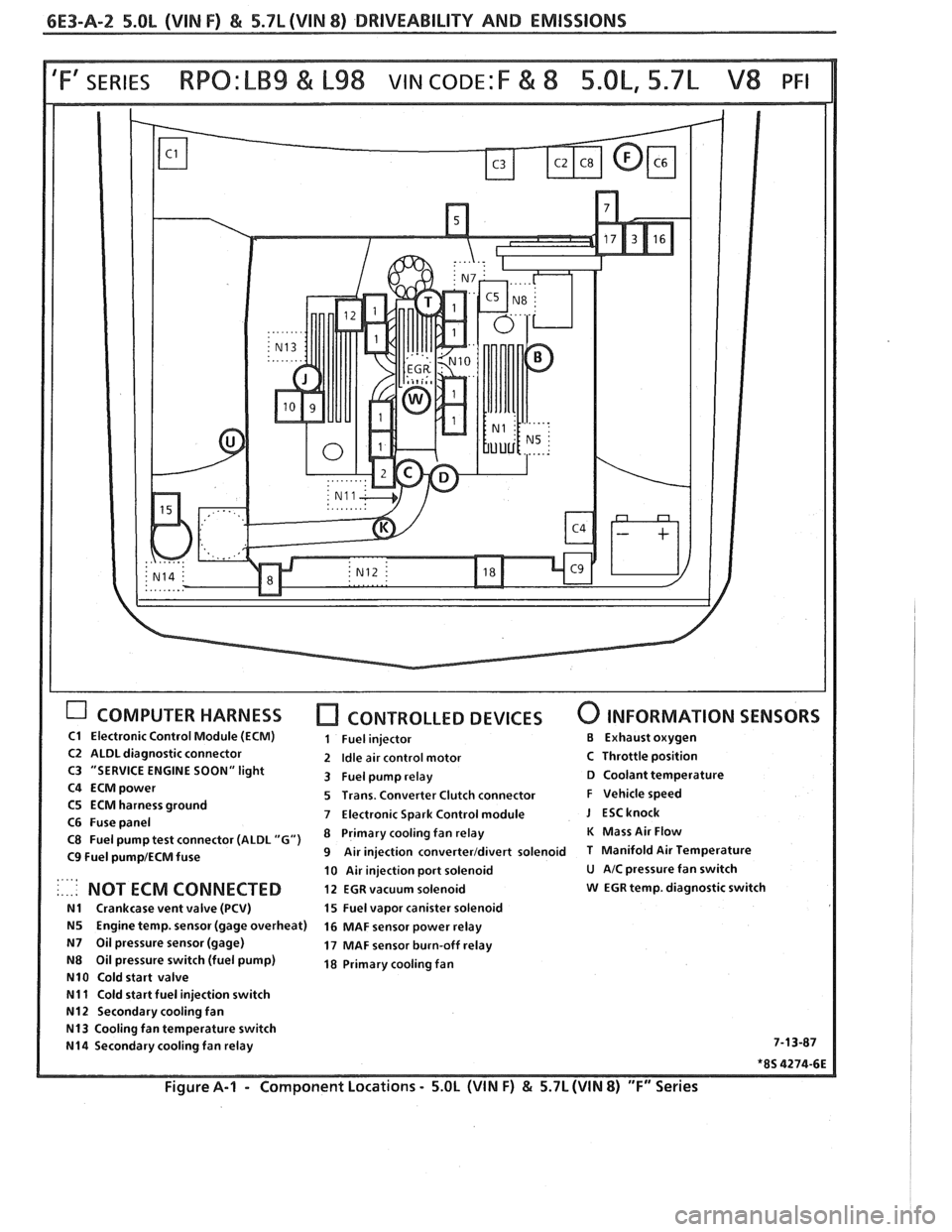
COMPUTER HARNESS [7 CONTROLLED DEVICES 0 INFORMATION SENSORS
C1 Electronic Control Module (ECM) 1 Fuel injector €3 Exhaust oxygen
C2 ALDL diagnostic connector 2 Idle air control motor C Throttle position
C3 "SERVICE ENGINE SOON" light
3 Fuel pump relay D Coolant temperature
C4
ECMpower 5 Trans. Converter Clutch connector F Vehicle speed
C5 ECM harness ground
7 Electronic Spark Control module J ESCknock C6 Fuse panel
C8 Fuel pump test connector (ALDL "G") Primary fan relay K Mass Air Flow
C9 Fuel pump1ECM fuse 9 Air injection converterldivert solenoid T Manifold Air Temperature
10 Air injection port solenoid
U AIC pressure fan switch . ., .. .. NOT ECM CONNECTED 12 EGR vacuum solenoid w EGR temp. diagnostic switch
N1 Crankcase vent valve (PCV) 15 Fuel vapor canister solenoid
N5 Engine temp. sensor (gage overheat)
16 MAF sensor power relay
N7 Oil pressure sensor (gage) 17 MAF sensor burn-off relay
N8 Oil pressure switch (fuel pump) 18 Primary cooling fan
N10 Cold start valve
N11 Cold start fuel injection switch
N12 Secondary cooling fan
N13 Cooling fan temperature switch
N14 Secondary cooling fan relay 7-13-87
*8S 4274-6E
Figure A-I - Component
Locations - 5.OL (WIN F) & 5.7L (WIN 8) "F" Series
Page 806 of 1825
DRIVEABILITY AND EMISSIONS 5.OL (VIN F) & 5.7L (VIN 8) 6E3-A-3
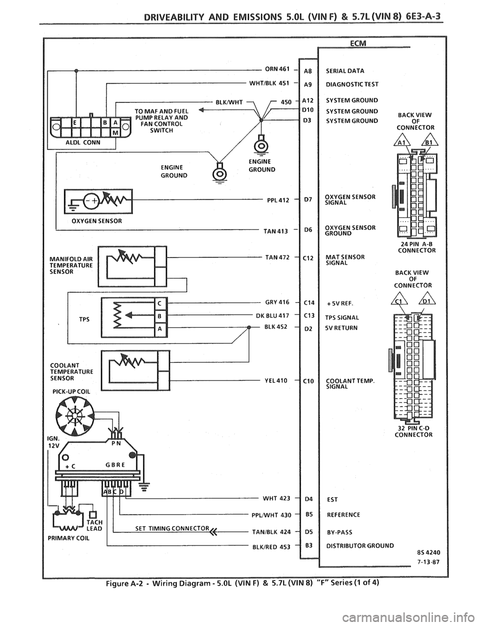
- ORN 461
T
TO MAF AND FUEL
PUMP RELAY AND
FAN CONTROL
SWITCH
ALDL CONN
I ENGINE
ENGINE GROUND
GROUND
-
OXYGEN SENSOR
TAN 413
MANIFOLD AIR TAN 472
TEMPERATURE SENSOR
GRY
416
K BLU 417
BLK 452
COOLANT
TEMPERATURE
SENSOR
YEL4lO
PICK-UP COlL
PRIMARY COlL I ..
- WHT
PPWHT
TANJBLK
BLWRED SERIAL
DATA
DIAGNOSTIC TEST
SYSTEM GROUND
SYSTEM GROUND
BACK
SYSTEM GROUND OF
CONNECTOR
OXYGEN SENSOR
SIGNAL
OXYGEN SENSOR
GROUND
24 PIN
A-0 CONNECTOR
MAT SENSOR
SIGNAL
BACK
VIEW OF
CONNECTOR
+ 5V REF.
TPS SIGNAL
5V RETURN
COOLANT TEMP.
SIGNAL
32 PIN C-D
CONNECTOR
EST
REFERENCE
BY-PASS
DISTRIBUTOR GROUND
8s 4240
7-13-87
Page 811 of 1825
6E3-A-8 5.OL (VIN F) & 5.7L(VIN 8) DRIVEABILITY AND EMISSIONS
DIAGNOSIC CIRCUIXCHECK
The Diagnostic Circuit Checlc is an organized approach to identifying a problem created by an Electronic
Engine Control System malfunction. It
must be the starting point for any driveability complaint diagnosis,
because it directs the Service Technician to the next logical step in diagnosing the complaint.
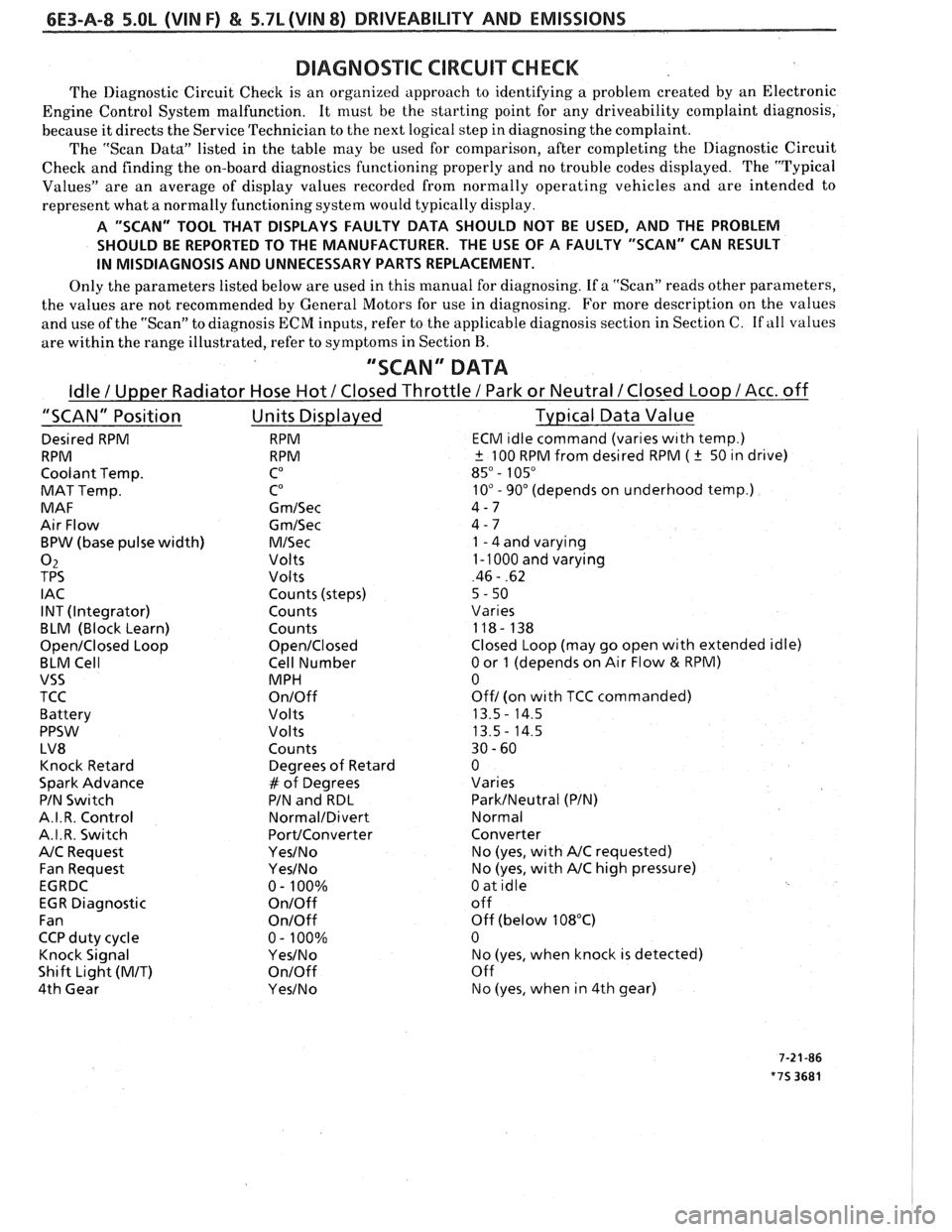
The "Scan Data" listed in the table may be used for comparison, after completing the Diagnostic Circuit
Check and finding the on-board diagnostics functioning properly and no trouble codes displayed. The "Typical
Values" are an average of display values recorded from normally operating vehicles and are intended to
represent what a normally functioning system would typically display.
A "SCAN" TOOL THAT DISPLAYS FAULTY DATA SHOULD NOT BE USED, AND THE PROBLEM
SHOULD BE REPORTED TO THE MANUFACTURER. THE USE OF A FAULTY "SCAN" CAN RESULT
IN MISDIAGNOSIS AND UNNECESSARY PARTS REPLACEMENT.
Only the parameters listed below are used in this manual for diagnosing. If a "Scan" reads other parameters,
the values are not recommended by General Motors for use in diagnosing. For more description on the values
and use of the "Scan" to diagnosis ECM inputs, refer to the applicable diagnosis section in Section C.
If all values
are within the range illustrated, refer to symptoms in Section
B.
"SCAN" DATA
Idle / Upper Radiator Hose Hot / Closed Throttle / Park or Neutral /Closed Loop /Acc. off
"SCAN" Position Units Displayed Typical Data Value
Desired RPM RPM ECM ~dle command (vanes w~th temp.)
RPM RPM
+ 100 RPM from desired RPM ( k 50 ~n drive)
Coolant Temp.
CO 85" - 105"
MAT Temp. CO 10" - 90" (depends on underhood temp.)
MAF G
m/Sec 4-7
Air Flow
Gm/Sec 4 - 7
BPW (base pulse width)
M/Sec 1 - 4 and varying
02 Volts 1 - 1000 and varying
TPS Volts 46 - .62
I AC Counts (steps)
5 - 50
INT (Integrator) Counts
Vanes
BLM (Block Learn) Counts 118- 138
Open/Closed Loop Open/Closed Closed Loop (may go open with extended idle)
BLM Cell Cell Number
0 or 1 (depends on Air Flow & RPM)
VSS MPH 0
TCC
On/Off Off/ (on wlth TCC commanded)
Battery Volts 13.5
- 14.5
PPSW
Volts 13.5- 14.5
LV8 Counts 30
- 60
Knock Retard Degrees
of Retard 0
Spark Advance
# of Degrees Varies
PIN
Swltch PIN and RDL ParkINeutral (PIN)
A.I. R. Control
Normal/Divert Normal
A.I.R. Switch
PortIConverter Converter
NC Request Yes/No No (yes, wlth NC requested)
Fan Request
Yes/No No (yes, with NC high pressure)
EGRDC 0- 100%
0 at idle
EGR Diagnostic
On/Off off
Fan
OnIOff Off (below 108°C)
CCP duty cycle 0
- 100% 0
Knock Signal
YesINo No (yes, when knock is detected)
Shift Light
(MIT) On/Off Off
4th Gear
Yes/No No (yes, when in 4th gear)
Page 825 of 1825
6E3-A-22 5.OL (VIN F) & 5.7L (VIN 8) DRIVEABILITY AND EMISSIONS
COLD START SWITCH
CONNECTOR
CLOSED BELOW
3S°C.
8 SEC. TIME LIMIT
COOLANT
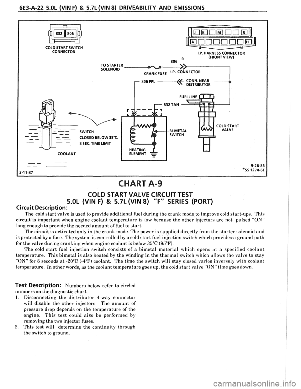
CHART A99
COLD START VALVE CIRCUIT TEST
5.OL (VIN F) & 5.7L (VIN 8) "F" SERIES (PORT)
Circuit Description:
The cold start valve is used to provide additional fuel cluring the crank mode to improve cold start-ups. This
circuit is important when engine coolant temperature is low because the other injectors are not pulsed
"ON"
long enough to provide the needed amount of fuel to start.
The circuit is activated only in the crank mode. The power is supplied directly from the starter solenoid and
is protected by a fuse. The system is controlled by a cold start fuel injection switch which provides a ground path
for the valve during cranking when engine coolant is below 35°C (95°F).
The cold start fuel injection switch consists of a bimetal material which opens at a specified coolant
temperature. This bimetal is also heated by the winding in the thertnal switch which allows the valve lo stay
"ON" for 8 seconds at -20°C (-4°F) coolant. The time the switch will stay closed varies inversely with coolant
temperature. In other words, as the coolant temperature goes up, the cold start valve
"ON" time goes down.
Test Description: Numbers below refer to circled
numbers on the diagnostic chart.
1. Disconnecting the distributor 4-way connector
will disable the other injectors. The amount of
pressure drop depends on the temperature of the
engine. This test could also be performed
by
removing the two injector fuses.
2. This test will determine the continuity through
the switch to ground.
Page 829 of 1825
6E3-A-26 5.OL (VIM F) & 5.7L (VIN 8) DRIVEABILITY AND EMISSIONS
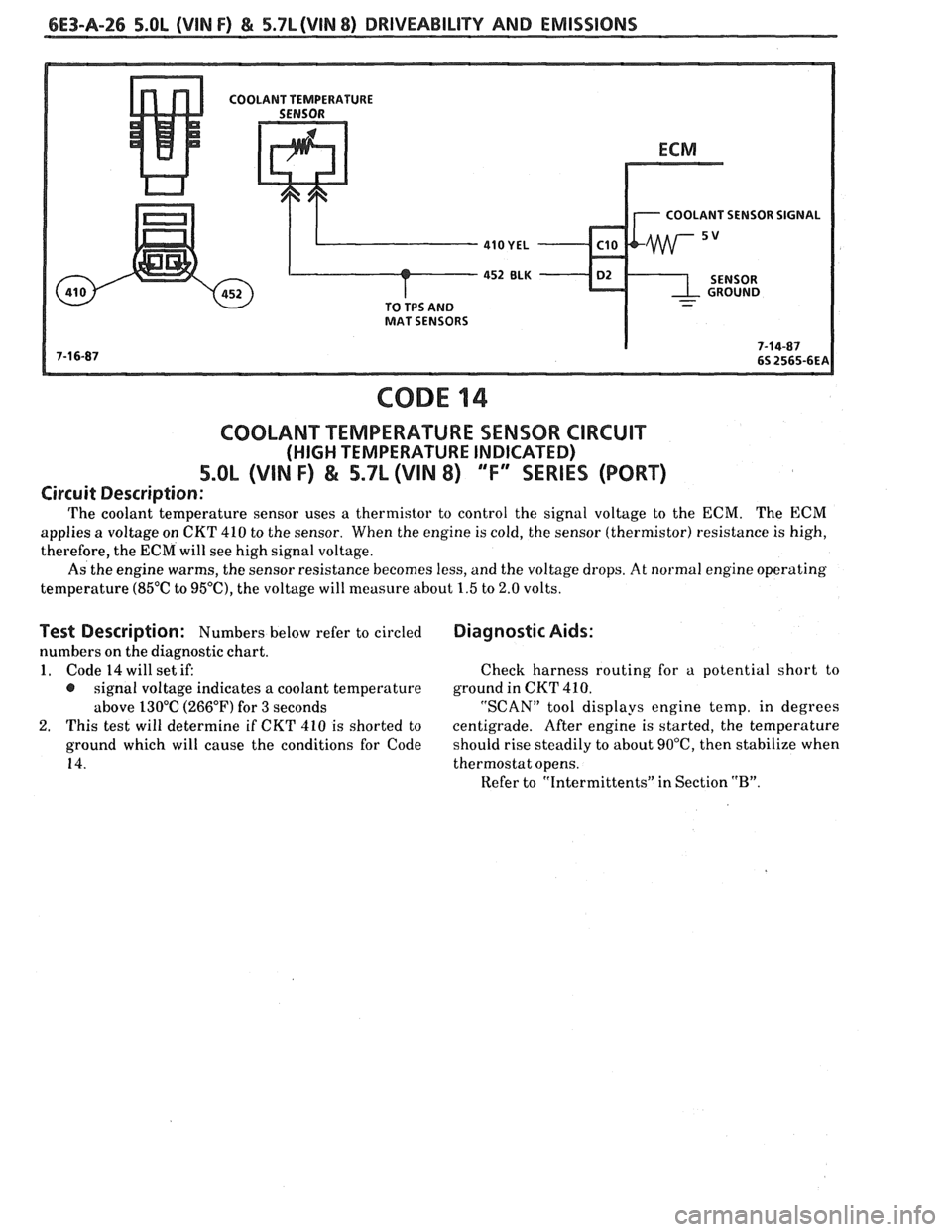
COOLANT SENSOR SIGNAL
-
CODE 14
COOLANT TEMPERATURE SENSOR CIRCUIT
(HIGH TEMPERATURE INDICATED)
5.OL (VIN F) & 5.7L (VIN 8) "F"" SERIES (PORT)
Circuit Description:
The coolant temperature sensor uses a thermistor to control the signal voltage to the ECM. The ECM
applies a voltage on CKT 410 to the sensor. When the engine is cold, the sensor (thermistor) resistance is high,
therefore, the ECM will see high signal voltage.
As the engine warms, the sensor resistance becomes less, and the voltage drops.
At normal engine operating
temperature
(85°C to 95"C), the voltage will measure about 1.5 to 2.0 volts.
Test Description: Numbers below refer to circled
numbers on the diagnostic chart.
1. Code 14 will set if:
@ signal voltage indicates a coolant temperature
above 130°C (266°F) for
3 seconds
2. This test will determine if CKT 410 is shorted to
ground which will cause the conditions for Code
14.
Diagnostic Aids:
Check harness routing for a potential short to
ground in
CKT 410.
"SCAN" tool displays engine temp, in degrees
centigrade. After engine is started, the temperature
should rise steadily to about
90°C, then stabilize when
thermostat opens.
Refer to "Intermittents" in Section
"B".
Page 830 of 1825
DRIVEABILITY AND EMISSIONS 5.0L (WIN F) & 5.7L (WIN 8) 6E3-A-27
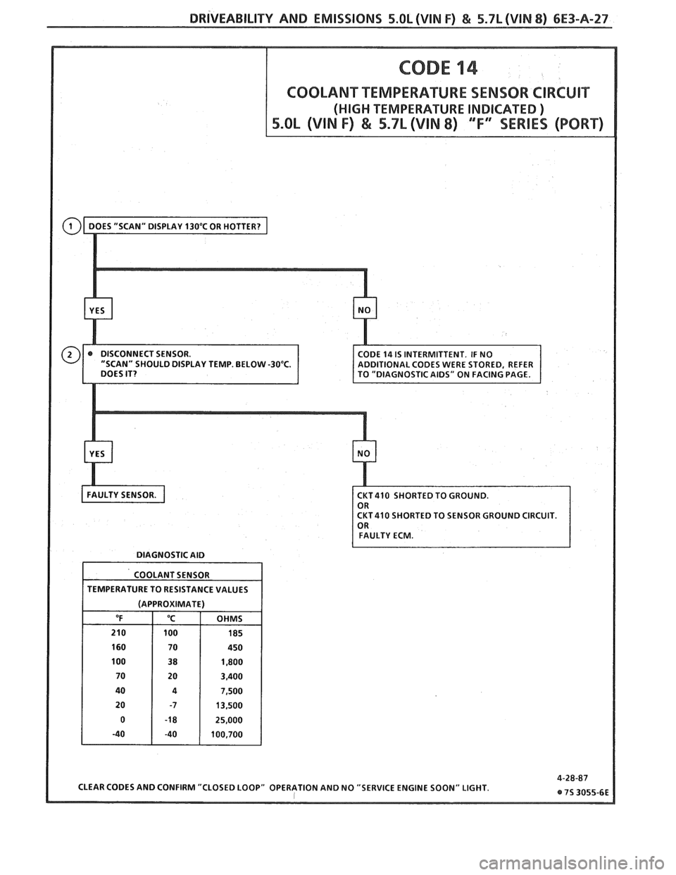
DIAGNOSTIC AID
COOLANT SENSOR
TEMPERATURE TO RESISTANCE VALUES
(APPROXIMATE)
CLEAR CODES AND CONFIRM "CLOSED LOOP" OPERATION AND NO "SERVICE ENGINE SOON" LIGHT.
Page 831 of 1825
6E3-A-28 S.OL (VIN F) & 5.7L (VIN 8) DRIVEABILITY AND EMISSIONS
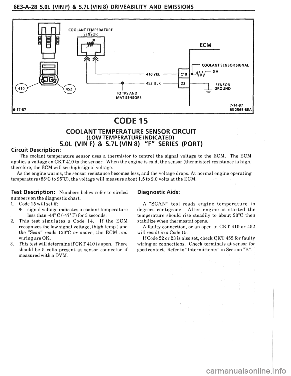
COOLANT SENSOR SIGNAL
CODE 15
COOLANT TEMPERATURE SENSOR CIRCUIT
(LOW TEMPERATURE INDICATED)
5.OL (VIN F) & 5.7L (VIN 8) 'Ti' SERIES (PORT)
Circuit Description:
The coolant temperature sensor uses a thermistor to control the signal voltage to the ECM. The ECM
applies a voltage on CKT 410 to the sensor. When the engine is cold, the sensor (thermistor) resistance is high,
therefore, the ECM will see high signal voltage.
As the engine warms, the sensor resistance becomes less, and the voltage drops. At normal engine operating
temperature (85°C to
95'0, the voltage will measure about 1.5 to 2.0 volts at the ECM.
Test Description: Numbers below refer to circled
numbers on the diagnostic chart.
1. Code 15 will set if:
@ signal voltage indicates a coolant temperature
less than
-44" C (-47" F) for 3 seconds.
2. This test simulates a Code 14. If the ECM
recognizes the low signal voltage, (high temp.)
and
the "Scan" reads 130°C or above, the ECM and
wiring are OK.
3. This test will determine if CKT 410 is open. There
should be 5 volts present at sensor connector if
measured with
a DVM.
Diagnostic Aids:
A "SCAN" tool reads engine temperature in
degrees centigrade. After engine is started the
temperature should rise steadily
to about 90°C then
stabilize when thermostat opens.
A faulty connection, or an open in CKT 410 or 452
will result in a Code 15.
If Code 22 or 23 is also set, check CKT 452 for faulty
wiring or connections. Check terminals at sensor for
good contact. Refer to "Intermittents" in Section
"R".
Page 833 of 1825
6E3-A-30 5.OL (VIN F) & 5.7L (VIN 8) DRIVEABILITY AND EMISSIONS
FRONT VIEW TO MAT AND
OF CONNECTOR
COOLANT
452
ELK D2
416 GRY - C14
CODE 21
THROmLE POSITION SENSOR (TPS) CIRCUIT
(SIGNAL VOLTAGE HIGH)
5.OL (VIN I") & 5.7L (VIN 8) 'T" SERIES (PORT)
Circuit Description:
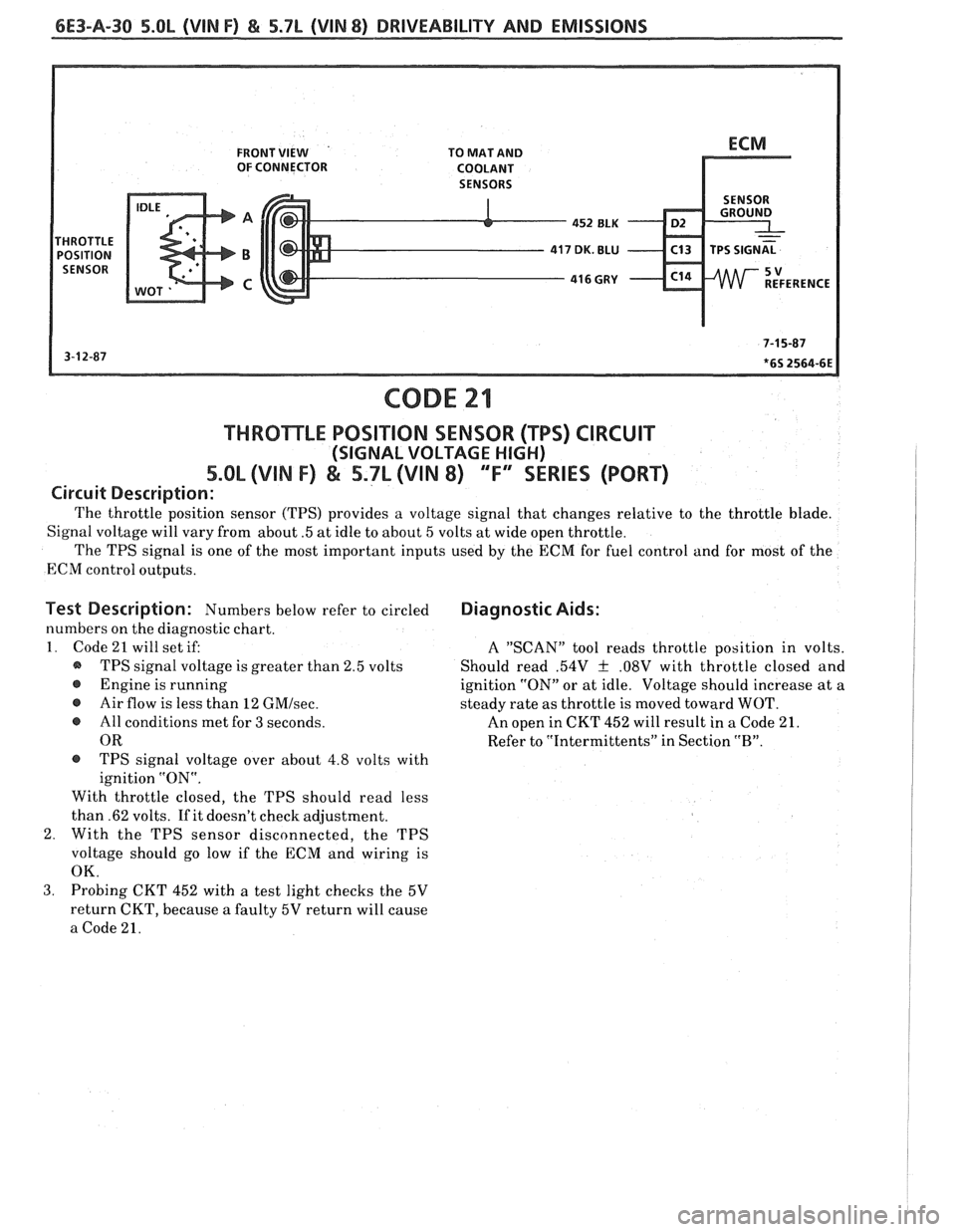
The throttle position sensor (TPS) provides a voltage signal that changes relative to the throttle blade.
Signal voltage will vary from about
.5 at idle to about 5 volts at wide open throttle.
The TPS signal is one of the most important inputs used by the ECM for fuel control and for most of the
ECM control outputs.
Test Description: Numbers below refer to circled
numbers on the diagnostic chart.
1. Code 21 will set if:
@ TPS signal voltage is greater than 2.5 volts
@ Engine is running
@ Air flow is less than 12 GMIsec.
e All conditions met for 3 seconds.
OR
@ TPS signal voltage over about 4.8 volts with
ignition "ON".
With throttle closed, the TPS should read less
than .62 volts. If it doesn't check adjustment.
2. With the TPS sensor disconnected, the TPS
voltage should go low if the ECM and wiring is
OK.
Diagnostic Aids:
A "SCAN" tool reads throttle position in volts.
Should read
.54V f .08V with throttle closed and
ignition "ON" or at idle. Voltage should increase at a
steady rate as throttle is moved toward WOT.
An open in CKT 452 will result in
a Code 21.
Refer to "Intermittents" in Section
"B".
3. Probing CKT 452 with a test light checks the 5V
return CKT, because
a faulty 5V return will cause
a Code 21.