Page 137 of 525

outboard pad and anti-squeal shim that fits
between the pad and the caliper body.
7Withdraw the inboard pad and anti-squeal
shim.
Refitting
8Proceed as described in Section 4,
paragraphs 10 and 11.
9Check that the cutaway recesses in the
pistons are positioned downwards, at
approximately 23°to the horizontal. A
template made of card may be used to check
the setting (see illustration). If necessary,
carefully turn the pistons to their correct
positions.
10Apply a little brake grease to the top and
bottom edges of the backplates on the new
brake pads.
11Locate the new pads and the anti-squeal
shims in the caliper. Ensure that the friction
material faces the disc, and check that the
pads are free to move slightly.
12Locate the anti-rattle spring on the pads,
then insert the pad retaining pins from the
inside edge of the caliper, while depressing
the spring. Tap the pins firmly into the caliper.
13Repeat the operations on the remaining
side of the vehicle.
14Proceed as described in Section 4,
paragraphs 17 to 20 inclusive.
6Rear brake shoes (drum
brakes) - inspection, removal
and refitting
3
Note: When working on the brake
components, take care not to disperse brake
dust into the air, or to inhale it, since it may
contain asbestos, which can damage your
health.
Inspection
1It is recommended that the brake shoes are
inspected when necessary by removing the
drums. This will enable a proper inspection of
the linings to be made, and additionally, the
wheel cylinders can be inspected for leaks. If
preferred, however, a provisional inspection of
the state of wear of the rear shoe linings can
be made by removing the plugs from the
inspection holes in the brake backplates.2Use a torch or inspection lamp, and if
necessary a mirror, to check that the friction
material has not worn down to less than the
specified minimum.
3If any one of the shoes has worn below the
specified limit, all four rear brake shoes must
be renewed as a set, as follows.
Removal
4Where applicable, remove the wheel trims,
then loosen the rear roadwheel bolts and
chock the front wheels. Jack up the rear of the
vehicle, and support on axle stands (see
“Jacking and Vehicle Support”) positioned
under the body side members. Remove the
roadwheels.
5Fully release the handbrake.
6Extract the drum securing screw and
remove the drum. If the drum is tight, remove
the plug from the inspection hole in the brake
backplate, and push the handbrake operating
lever towards the brake shoe to move the
shoes away from the drum. If necessary,
slacken the handbrake cable adjuster (see
illustrations).
7Note the location and orientation of all
components before dismantling, as an aid to
reassembly.
8Clean the dust and dirt from the drum and
shoes, but take care not to inhale it.
9Remove the shoe hold-down pins, springs
and cups by depressing the cups and turning
them through 90°using a pair of pliers (see
illustrations). Note that the hold-down pins
are removed through the rear of the brake
backplate.
10Disconnect the handbrake cable from the
operating lever.11The upper and lower return springs may
now be unhooked and the shoes removed
separately, or the assembly of shoes, adjuster
strut and springs may be removed together.
Remove the hub, refer to Chapter 10, if
necessary. Take care not to damage the
wheel cylinder rubber boots. Before removing
the return springs, note the position and
orientation of the springs and adjuster strut.
12If the shoes are to be removed for some
time, fit a stout rubber band or a spring clip to
the wheel cylinder, to prevent the pistons from
being pushed out of their bores. In any event,
do not press the brake pedal while the drum is
removed.
Refitting
13Clean the dust and dirt from the brake
backplate, but take care not to inhale it.
14Apply a small amount of brake grease to
the shoe rubbing areas on the backplate.
15Investigate and rectify any source of
contamination of the linings (wheel cylinder or
hub bearing oil seal leaking).
16Although linings are available separately
(without shoes), renewal of the shoes
complete with linings is to be preferred,
unless the reader has the necessary skills and
equipment to fit new linings to the old shoes.
17If not already done, dismantle the shoes,
strut and springs. Note the position and
orientation of the components. On later
models (1992-on), the brake shoe lower
anchorage has been modified so that it is now
rectangular, necessitating modified brake
shoes and a modified lower return spring (see
illustration).
9•6Braking system
5.9 Checking a rear caliper piston cut
away recess angle with a card template6.6B Push the handbrake operating lever
to move the shoes away from the drum
6.9B . . . then withdraw the cup and spring6.9A Release the shoe hold-down cup . . .
6.6A Extracting a brake drum securing
screw
Page 138 of 525

18If both brake assemblies are dismantled
at the same time, take care not to mix up the
components. Note that the left-hand and
right-hand adjuster components are marked.
The threaded rod is marked “L” or “R”, and
the other “handed” components are colour-
coded black for the left-hand side, and silver
for the right-hand side.
19Dismantle and clean the adjuster strut.
Apply a smear of silicone-based grease to the
adjuster threads.
20Examine the return springs. If they are
distorted, or if they have seen extensiveservice, renewal is advisable. Weak springs
may cause the brakes to bind.
21If a new handbrake operating lever was
not supplied with the new shoes (where
applicable), transfer the lever from the old
shoes. The lever may be secured with a pin
and circlip, or by a rivet, which will have to be
drilled out.
22If the components are to be refitted as an
assembly, assemble the new shoes, springs
and adjuster components. Expand the
adjuster strut to ease fitting (see
illustrations).
23Offer the shoes to the brake backplate. Be
careful not to damage the wheel cylinder
boots, or to displace the pistons. Remember
to remove the rubber band or spring clip from
the wheel cylinder, where applicable.
24When the shoes are in position, insert the
hold-down pins and secure them with the
springs and cups (see illustration).
25Reconnect the handbrake cable, then refit
the hub, and adjust the bearing if the hub was
removed.
26Fitting the shoes and springs together as
an assembly may be too difficult. It is possible
to fit the shoes and secure them with the
hold-down pins and then fit the adjuster strut,
the return springs and adjuster.27Back off the adjuster wheel to reduce the
length of the strut, until the brake drum will
pass over the shoes.
28Make sure that the handbrake operating
lever is correctly positioned, with the pin on
the edge of the shoe web, not riding on top of
it, then refit and secure the brake drum.
29Repeat the operations on the remaining
side of the vehicle.
30Adjust the brakes by operating the
footbrake at least fifteen times. A clicking
noise will be heard at the drums, as the
automatic adjusters operate. When the
clicking stops, adjustment is complete.
31Check the handbrake adjustment, as
described in Section 26.
32Refit the roadwheels, and lower the
vehicle to the ground. Do not fully tighten the
roadwheel bolts until the vehicle is resting on
its wheels.
33New brake linings should be carefully
bedded-in and, where possible, heavy braking
should be avoided during the first 100 miles
(160 km) or so after fitting new linings.
7Handbrake shoes (rear disc
brakes) - inspection, removal
and refitting
3
Note: When working on the brake
components, take care not to disperse brake
dust into the air, or to inhale it, since it may
contain asbestos, which can damage your
health.
Inspection
1Although 2.0 litre models are fitted with rear
disc brakes, the handbrake operates
independently of the footbrake, using brake
shoes on the inside of the disc in a similar way
to rear drum brake models.
2To inspect the handbrake shoes on all
SOHC models, it is necessary to remove the
hub/disc, as described in Chapter 10.
3To inspect the handbrake shoes on DOHC
models it will be necessary to remove the
brake disc, as described in Section 10.
4With the hub/disc or the disc (as applicable)
removed, check that the friction material has
not worn down to less than the specified
minimum.
Braking system 9•7
6.22A Right-hand adjuster strut correctly
fitted to shoes
6.24 Rear brake components correctly
assembled (hub removed for clarity)6.22C Adjuster lever spring fitted to
leading shoe6.22B Fitting the upper return spring to
the shoes
6.17 Modified rear brake shoe lower anchorage - 1992-on models
9
Page 139 of 525

5If any one of the shoes has worn below the
specified limit, all four handbrake shoes must
be renewed as a set, as follows.
SOHC models
Removal
6Clean the dust and dirt from the various
components, but take care not to inhale it.
7Disconnect the handbrake cable and the
return spring from the handbrake operating
lever at the brake backplate. If necessary,
slacken the handbrake cable adjustment, with
reference to Section 26.
8Remove the shoe hold-down pins, springs
and cups by depressing the cups and turning
them through 90°using a pair of pliers. Note
that the hold-down pins are removed through
the rear of the brake backplate.
9The shoes, adjuster, handbrake operating
lever and return springs can now be removed
together as an assembly.
10Note the position and orientation of all
components, then unhook the upper and
lower return springs from the shoes, and
recover the handbrake operating lever and the
adjuster.
Refitting
11Apply a little brake grease to the threads
of the adjuster, then screw it together to its
minimum length. Also apply a little brake
grease to the shoe rubbing areas on the
lockplate.
12Fit one of the new brake shoes, and
secure it to the backplate with the hold-down
pin, spring and cup.
13Fit the handbrake operating lever in
position.
14Fit the remaining brake shoe, and secure
with the hold-down pin, spring and cup.
15Hook the upper return spring onto the
shoes.
16Fit the adjuster between the lower ends of
the shoes, as noted before dismantling, then
fit the lower return spring (see illustrations).
17Reconnect the handbrake cable and the
return spring to the handbrake operating
lever.
18Refit the hub/disc, and adjust the wheel
bearing play, as described in Chapter 10, but
do not refit the roadwheel at this stage.
19Repeat the operations on the remaining
side of the vehicle.20Check the handbrake cable adjustment,
as described in Section 26.
21Refit the roadwheels and lower the vehicle
to the ground. Do not fully tighten the
roadwheel bolts until the vehicle is resting on
its wheels.
DOHC models
Removal
22Proceed as described in paragraphs 6
and 7.
23Remove the shoe hold-down pins, springs
and cups by turning the cups through using a
screwdriver. Note that the hold-down pins are
removed through the rear of the brake
backplate. Note also the position and
orientation of all components, then unhook
the upper and lower return springs from the
shoes, and recover the handbrake operating
lever and the adjuster.
Refitting
24Proceed as described in paragraphs 11 to
14 inclusive.
25Hook the lower return spring onto the
shoes.
26Fit the adjuster between the upper ends of
the shoes, as noted before dismantling, then
fit the upper return spring (see illustration).
27Reconnect the handbrake cable and the
return spring to the handbrake operating
lever.
28Refit the brake disc as described in
Section 10, but do not refit the roadwheel at
this stage.
29Proceed as described in paragraphs 19
to 21 inclusive.
8Front disc caliper - removal,
overhaul and refitting
3
Note: Refer to the note at the beginning of
Section 3 before proceeding. Before
dismantling a caliper, check that replacement
parts can be obtained, and retain the old
components to compare them with the new
ones. New sealing rings must be used on the
fluid hose union bolt on refitting
Models with solid discs
Removal
1Where applicable, remove the wheel trims,
then loosen the relevant front roadwheel bolts
and apply the handbrake. Jack up the front of
the vehicle, and support securely on axle
stands (see “Jacking and Vehicle Support”)
positioned under the body side members.
Remove the roadwheel.
2Remove the brake disc pads, as described
in Section 4.
3Working under the bonnet, remove the
brake fluid reservoir cap, and secure a piece
of polythene over the filler neck with a rubber
band, or by refitting the cap. This will reduce
the loss of fluid during the following
procedure.
4Unscrew the brake fluid hose union bolt
from the rear of the caliper, and disconnect
the hose. Recover the two sealing rings from
the union bolt (one either side of the hose end
fitting). Be prepared for fluid spillage, and plug
the open ends to prevent dirt ingress and
further fluid loss.
5Prise out the two caliper bracket mounting
bolt dust caps from the inboard edge of the
caliper bracket, then using an Allen key or
hexagon bit, unscrew the mounting bolts, and
withdraw the caliper assembly from the
vehicle.
Overhaul
6If desired, the caliper can be overhauled as
follows. Otherwise, go on to paragraph 24 for
details of refitting.
7Brush the dirt and dust from the caliper, but
take care not to inhale it.
8Mount the caliper bracket in a soft-jawed
vice. Then separate the caliper body from the
mounting bracket by pressing the front face of
the caliper body downwards and simultane-
ously sliding the caliper body from the
locating pins on the bracket. Recover the
guide springs from the bracket, noting their
orientation.
9Using a screwdriver, prise the dust seal
retaining clip from the piston dust seal, then
carefully prise off the dust seal.
10Place a thin piece of wood in front of the
piston to prevent it from falling out of its bore
and sustaining damage. Then apply low air
pressure - e.g. from a foot pump - to the
hydraulic fluid union hole in the rear of the
caliper body, to eject the piston from its bore.
9•8Braking system
7.16A Fitting the lower shoe return spring
- SOHC models
7.26 Handbrake shoe adjuster and upper
return spring correctly fitted - DOHC models
7.16B Handbrake shoe components
correctly assembled - SOHC models
Page 140 of 525

11Remove the wood and carefully withdraw
the piston.
12Carefully prise the seal from the groove in
the caliper piston bore, using a plastic or
wooden instrument.
13Inspect the surfaces of the piston and its
bore in the caliper for scoring, or evidence of
metal-to-metal contact. If evident, renew the
complete caliper assembly.
14If the piston and bore are in good
condition, discard the seals and obtain a
repair kit, which will contain all the necessary
renewable items.
15Clean the piston and cylinder bore with
brake fluid or methylated spirit, nothing else!
16Begin reassembly by fitting the seal into
the caliper bore.
17Locate the dust seal in its groove in the
piston. Dip the piston in clean brake fluid and
insert it squarely into the cylinder. Check that
the cutaway recesses in the piston are
positioned horizontally. If necessary, carefully
turn the piston to its correct position.
18When the piston has been partially
depressed, engage the dust seal with the rim
of the caliper bore, and fit the retaining clip.
19Push the piston further into its bore, but
not as far as the stop, ensuring that it does
not jam.
20If desired, the caliper body locating pin
rubbers can be renewed. Extract the nylon
compression sleeve from within each rubber,
then carefully compress the rubber shoulder,
and push the rubber through the hole in the
caliper body to remove it from the inboard
end (see illustrations).
21Fit the new rubbers using a reversal of the
removal procedure.
22Secure the caliper bracket in a soft-jawed
vice, and refit the guide springs in the
positions noted before removal.
23Engage the caliper body with the locating
pins on the bracket, then press the caliper
body into position until the locating pin
rubbers in the caliper body rest against the
bracket.
Refitting
24Refit the caliper bracket to the hub carrier,
and tighten the securing bolts to the specified
torque. Refit the dust caps to the bolts.25Reconnect the brake fluid hose union,
using new sealing rings on the union bolt.
26Refit the disc pads, as described in
Section 4.
27Remove the polythene from the brake
fluid reservoir filler neck, and bleed the
relevant brake hydraulic circuit, as described
in Section 3.
28Refit the roadwheel and lower the vehicle
to the ground. Do not fully tighten the
roadwheel bolts until the vehicle is resting on
its wheels.
Models with ventilated discs
Removal
29Proceed as described in paragraphs 1 to 4
inclusive.
30Withdraw the caliper body from the
vehicle.
31If desired, the caliper bracket can be
removed from the hub carrier by unscrewing
the two securing bolts (see illustration).
Overhaul
32To overhaul the caliper, continue as
follows. Otherwise, go on to paragraph 42 for
details of refitting.
33Brush the dirt and dust from the caliper,
but take care not to inhale it.
34Using a screwdriver, carefully prise the
dust seal from the end of the piston and the
caliper body, and remove it.
35Proceed as described in paragraphs 10
to 15 inclusive.
36Begin reassembly by fitting the seal into
the caliper bore.
37Locate the dust seal in its groove in the
piston. Dip the piston in clean brake fluid and
insert it squarely into the cylinder. Check that
the cutaway recesses in the piston are
positioned vertically. If necessary, carefully
turn the piston to its correct position.
38When the piston has been partially
depressed, engage the dust seal with the rim
of the caliper bore.
39Push the piston further into its bore, but
not as far as the stop, ensuring that it does
not jam.
40If desired, the guide bolt sleeves can be
renewed. Extract the nylon compression
sleeve from within each rubber, then carefullycompress the rubber shoulder, and push the
rubber through the hole in the caliper body to
remove it from the inboard end.
41Fit the new sleeves using a reversal of the
removal procedure.
Refitting
42Where applicable, refit the caliper bracket
to the hub carrier, and tighten the securing
bolts to the specified torque.
43Proceed as described in paragraphs 25
to 28 inclusive.
9Rear disc caliper - removal,
overhaul and refitting
3
Note: Refer to the note at the beginning of
Section 3 before proceeding. Before
dismantling a caliper, check that replacement
parts can be obtained, and retain the old
components to compare them with the new
ones
Removal
1Where applicable, remove the wheel trim,
then loosen the relevant rear roadwheel bolts
and check the front wheels. Jack up the rear
of the vehicle, and support on axle stands
(see “Jacking and Vehicle Support”)
positioned under the body side members.
Remove the roadwheel.
2Remove the disc pads, as described in
Section 5.
3Working under the bonnet, remove the
brake fluid reservoir cap and secure a piece of
polythene over the filler neck with a rubber
band, or by refitting the cap. This will reduce
the loss of fluid during the following
procedure.
4Unscrew the brake fluid pipe union nut from
the rear of the caliper, and disconnect the
pipe. Take care not to strain the pipe. Be
prepared for fluid spillage, and plug the open
ends to prevent dirt ingress and further fluid
loss.
5Unscrew the two mounting bolts and
withdraw the caliper from the vehicle, noting
that on DOHC models, the caliper securing
bolts also secure the ABS sensor bracket (see
illustrations). Take care not to strain the ABS
sensor wiring, where applicable.
Braking system 9•9
8.31 Caliper bracket securing bolts
(arrowed) - model with ventilated discs8.20B . . . then withdraw the caliper
locating pin rubber - model with
solid discs8.20A Extract the nylon compression
sleeve (arrowed) . . .
9
Page 141 of 525

Overhaul
6If desired, the caliper can be overhauled as
follows. Otherwise, go on to paragraph 20 for
details of refitting.
7Brush the dirt and dust from the caliper, but
take care not to inhale it.
8Note that no attempt must be made to
separate the two halves of the caliper.
9Using a screwdriver, prise the dust seal
retaining clips from the piston dust seals, then
carefully prise off the dust seals.
10Using a clamp, secure one of the pistons
in its fully retracted position. Then apply low
air pressure (e.g. from a foot pump), to the
hydraulic fluid union hole in the rear of the
caliper body, to eject the remaining piston
from its bore. Take care not to drop the
piston, which may result in damage.
11Temporarily close off the bore of the
removed piston, using a flat piece of wood or
similar improvised tool. Then remove the
clamp from the remaining piston, and again
apply air pressure to the caliper union to eject
the piston.
12Carefully prise the seals from the grooves
in the caliper piston bores, using a plastic or
wooden instrument.
13Inspect the surfaces of the pistons and
their bores in the caliper for scoring, or
evidence of metal-to-metal contact. If evident,
renew the complete caliper assembly.
14If the pistons and bores are in good
condition, discard the seals and obtain a
repair kit, which will contain all the necessary
renewable items. Also obtain a tube of brake
cylinder paste.
15Clean the piston and cylinder bore with
brake fluid or methylated spirit - nothing else!
16Apply a little brake cylinder paste to the
pistons, cylinder bores and piston seals.
17Begin reassembly by fitting the seals to
the grooves in the caliper bores.
18Locate the dust seals in their grooves in
the pistons, then insert the pistons carefully
into their bores until they enter the seals. It
may be necessary to rotate the pistons to
prevent them from jamming in the seals.
19When the pistons have been partially
depressed, engage the dust seals with the
rims of the caliper bores, and fit the retaining
clips.
Refitting
20Refit the caliper and tighten the securing
bolts to the specified torque, ensuring that the
ABS sensor bracket is in position, where
applicable.
21Reconnect the brake fluid pipe to the
caliper, and tighten the union nut.
22Refit the disc pads, as described in
Section 5.
23Remove the polythene from the brake
fluid reservoir filler neck and bleed the
relevant brake hydraulic circuit, as described
in Section 3.
24Refit the roadwheel and lower the vehicle
to the ground. Do not fully tighten the
roadwheel bolts until the vehicle is resting on
its wheels.
10Brake disc - inspection,
removal and refitting
3
Inspection
1Where applicable, remove the wheel trim,
then loosen the relevant roadwheel bolts. If
checking a front disc, apply the handbrake,
and if checking a rear disc, chock the front
wheels, then jack up the relevant end of the
vehicle and support on axle stands (see
“Jacking and Vehicle Support”) positioned
under the body side members. Remove the
roadwheel.
2Where applicable, check that the brake disc
securing screw is tight. Then fit a spacer
approximately 10.0 mm (0.4 in) thick to one of
the roadwheel bolts, and refit and tighten the
bolt in the hole opposite the disc securing
screw (see illustration).
3Rotate the brake disc, and examine it for
deep scoring or grooving. Light scoring is
normal, but if excessive, the disc should be
removed and either renewed or machined
(within the specified limits) by an engineering
works.
4Using a dial gauge, or a flat metal block and
feeler blades, check that the disc run-out does
not exceed the figure given in the Specifications.
Measure the run-out 10.0 mm (0.4 in) in from the
outer edge of the disc. 5On all SOHC models, if the rear disc run-
out is excessive, check the rear wheel bearing
adjustment, as described in Chapter 10.
6If the front disc run-out (all models), or the
rear disc run-out (DOHC models), is
excessive, remove the disc as described later
in this Section. Check that the disc-to-hub
surfaces are perfectly clean. Refit the disc and
check the run-out again.
7If the run-out is still excessive, the disc
should be renewed.
8To remove a disc, continue as follows.
Front disc
Removal
9Where applicable, remove the roadwheel
bolt and spacer used when checking the disc.
10Remove the disc pads, (Section 4).
11On 2.0 litre models, unscrew the two
securing bolts and remove the caliper
bracket.
12Remove the securing screw and withdraw
the disc from the hub, where applicable tilting
it to clear the brake caliper (see illustration).
Refitting
13Refitting is a reversal of removal, but
make sure that the mating faces of the disc
and hub are perfectly clean, and apply a little
locking fluid to the threads of the securing
screw. Refit the disc pads, (Section 4).
Rear disc - SOHC models
14On these models, the disc is integral with
the rear hub, and removal and refitting is
described in Chapter 10.
9•10Braking system
9.5A Withdrawing a rear caliper mounting
bolt . . .10.2 Refit a wheel bolt and spacer
(arrowed) opposite the disc securing screw
(A) before checking brake disc run-out
10.12 Removing a disc securing screw -
SOHC model
9.5B . . . which also secures the ABS
sensor bracket - DOHC model
Page 142 of 525

Rear disc - DOHC models
Removal
15Where applicable, remove the roadwheel
bolt and spacer used when checking the disc.
16Remove the disc pads, as described in
Section 5.
17Remove the brake caliper with reference
to Section 9, but leave the hydraulic fluid pipe
connected. Move the caliper to one side, and
suspend it using wire or string to avoid
straining the pipe.
18Remove the securing screw and withdraw
the disc from the hub (see illustration). If the
disc is tight, collapse the handbrake shoes by
inserting a screwdriver through the adjuster
hole in the disc and turning the adjuster
wheel.
Refitting
19Refitting is a reversal of removal, but
make sure that the mating faces of the disc
and hub are perfectly clean, and apply a little
locking fluid to the threads of the securing
screw. Refit the disc pads, as described in
Section 5.
11Brake drum - removal,
inspection and refitting
3
Note: When working on the brake
components, take care not to disperse brake
dust into the air, or to inhale it, since it may
contain asbestos, which can damage your
health.
Removal
1Where applicable, remove the wheel trim,
then loosen the relevant rear roadwheel bolts
and chock the front wheels. Jack up the rear
of the vehicle, and support on axle stands
(see “Jacking and Vehicle Support”)
positioned under the body side members.
Remove the roadwheel.
2Fully release the handbrake.
3Extract the drum securing screw and
remove the drum. If the drum is tight, remove
the plug from the inspection hole in the brake
backplate, and push the handbrake operating
lever towards the brake shoe to move theshoes away from the drums. If necessary,
slacken the handbrake cable adjuster.
Inspection
4Brush the dirt and dust from the drum,
taking care not to inhale it.
5Examine the internal friction surface of the
drum. If they are deeply scored, or so worn
that the drum has become ridged to the width
of the shoes, then both drums must be
renewed.
6Regrinding of the friction surface is not
recommended, since the internal diameter of
the drum will no longer be compatible with the
shoe friction material contact diameter.
Refitting
7Refit the brake drum and tighten the
securing screw. If necessary, back off the
adjuster wheel until the drum will pass over
the shoes.
8Adjust the brakes by operating the
footbrake a number of times. A clicking noise
will be heard at the drum as the automatic
adjuster operates. When the clicking stops,
adjustment is complete.
9Refit the roadwheel and lower the vehicle to
the ground. Do not fully tighten the roadwheel
bolts until the vehicle is resting on its wheels.
12Rear wheel cylinder (drum
brakes) - removal, overhaul
and refitting
3
Note: Refer to the notes at the beginning of
Sections 3 and 11 before proceeding. Before
dismantling a wheel cylinder, check that
replacement parts can be obtained, and retain
the old components to compare them with the
new ones
Removal
1Where applicable, remove the wheel trim,
then loosen the relevant rear roadwheel bolts
and chock the front wheels. Jack up the rear
of the vehicle and support on axle stands (see
“Jacking and Vehicle Support”) positioned
under the body side members. Remove the
roadwheel.
2Fully release the handbrake.3Extract the drum securing screw and
remove the drum. If the drum is tight, remove
the plug from the inspection hole in the brake
backplate, and push the handbrake operating
lever towards the brake shoe to move the
shoes away from the drum. If necessary,
slacken the handbrake cable adjuster.
4Using a pair of pliers, unhook the upper
return spring from the brake shoes, noting its
orientation, then push the upper ends of the
shoes apart until they are clear of the wheel
cylinder (see illustration).
5Working under the bonnet, remove the
brake fluid reservoir cap and secure a piece of
polythene over the filler neck with a rubber
band, or by refitting the cap. This will reduce
the loss of fluid during the following
procedure.
6Unscrew the brake fluid pipe union nut from
the rear of the wheel cylinder, and disconnect
the pipe (see illustration). Take care not to
strain the pipe. Be prepared for fluid spillage,
and plug the open ends to prevent dirt ingress
and further fluid loss.
7Unscrew the two securing bolts from the
rear of the brake backplate, and withdraw the
wheel cylinder.
Overhaul
8If desired, the wheel cylinder can be
overhauled as follows. Otherwise, go on to
paragraph 17 for details of refitting.
9Brush the dirt and dust from the wheel
cylinder, but take care not to inhale it.
10Pull the rubber dust seals from the ends of
the cylinder body.
11The pistons will normally be ejected by
the pressure of the coil spring. If they are not,
tap the end of the cylinder body on a piece of
wood, or apply low air pressure (e.g. from a
foot pump), to the hydraulic fluid union hole in
the rear of the cylinder body, to eject the
pistons from their bores.
12Inspect the surfaces of the pistons and
their bores in the cylinder body for scoring, or
evidence of metal-to-metal contact. If evident,
renew the complete wheel cylinder assembly.
Note that the later type of wheel cylinder can
be used to replace the early type as a
complete unit.
Braking system 9•11
12.6 Unscrewing rear wheel cylinder brake
fluid pipe union12.4 Rear brake assembly
1 Wheel cylinder
2 Upper shoe return spring (note
orientation)
10.18 Withdrawing the rear brake disc -
DOHC model
9
Page 143 of 525
, are
fitted with L-shaped pist")
13If the pistons and bores are in good
condition, discard the seals and obtain a
repair kit, which will contain all the necessary
renewable items. Later models (1992-on), are
fitted with L-shaped piston seals (see
illustrations). Ensure that the correct repair
kit is obtained when overhauling a wheel
cylinder, as the early and later components
are not interchangeable.
14Lubricate the piston seals with clean
brake fluid, and insert them into the cylinder
bores with the spring between them, using
finger pressure only.
15Dip the pistons in clean brake fluid, and
insert them into the cylinder bores.
16Fit the dust seals, and check that the
pistons can move freely in their bores.
Refitting
17Refit the wheel cylinder to the backplate,
and tighten the securing bolts.
18Reconnect the brake fluid pipe to the
cylinder, and tighten the union nut.
19Push the brake shoes against the pistons,
then refit the upper return spring as noted
before removal.
20Refit the brake drum and tighten the
securing screw. If necessary, back off the
adjuster wheel until the drum will pass over
the shoes.
21Remove the polythene from the brake
fluid reservoir filler neck, and bleed the
relevant brake hydraulic circuit, as described
in Section 3.
22Adjust the brakes by operating the
footbrake a number of times. A clicking noise
will be heard at the drum as the automatic
adjuster operates. When the clicking stops,
adjustment is complete.
23Refit the roadwheel and lower the vehicle
to the ground. Do not fully tighten the
roadwheel bolts until the vehicle is resting on
its wheels.
13Rear brake backplate -
removal and refitting
3
Models with rear drum brakes
Removal
1Where applicable, remove the wheel trim,
then loosen the relevant rear roadwheel bolts
and chock the front wheels. Jack up the rear
of the vehicle, and support on axle stands
(see “Jacking and Vehicle Support”)
positioned under the body side members.
Remove the roadwheel.
2Remove the brake drum with reference to
Section 11.
3Remove the rear hub, (Chapter 10).
4Remove the brake shoes, (Section 6).
5Remove the brake wheel cylinder, as
described in Section 12.
6Using a screwdriver, prise out the lockplate
that secures the handbrake cable in the
backplate.
7Unscrew the four securing bolts, and
withdraw the stub axle and backplate.
Refitting
8Refitting is a reversal of removal,
remembering the following points.
9Coat the rear face of the stub axle flange
with a little lithium-based grease.
10Tighten the brake backplate/stub axle
securing bolts to the specified torque, in the
three stages given in the Specifications.
11Refit the brake wheel cylinder, as
described in Section 12.
12Refit the brake shoes, as described in
Section 6.
13Refit the rear hub, as described in
Chapter 10.
14Refit the brake drum with reference to
Section 11.
15Before refitting the roadwheel and
lowering the vehicle to the ground, check and
if necessary adjust the handbrake, as
described in Section 26.
Models with rear disc brakes
(SOHC models)
Removal
16Proceed as described in paragraphs 1
to 7.
17Remove the rear hub/disc, (Chapter 10).
18Remove the handbrake shoes, (Section 7).
19Unscrew the four securing bolts, and
withdraw the stub axle and lockplate.
Refitting
20Refitting is a reversal of removal,
remembering the following points.
21Coat the rear face of the stub axle flange
with a little lithium-based grease.
22Tighten the brake backplate/stub axle
securing bolts to the specified torque, in the
three stages given in the Specifications.
23Refit the handbrake shoes, as described
in Section 7.
24Refit the rear hub/disc, (Chapter 10).
25Before refitting the roadwheel and
lowering the vehicle to the ground, check and
if necessary adjust the handbrake, as
described in Section 26.
DOHC models
Removal
26Proceed as described in paragraphs 1
to 7.
27Remove the brake disc (Section 10).
28Remove the rear hub, (Chapter 10).
29Remove the handbrake shoes, (Section 7).
30Using a splined key, unscrew the four
securing bolts and withdraw the backplate.
Refitting
31Refitting is a reversal of removal,
remembering the following points.
32Refit the handbrake shoes, (Section 7).
33Refit the rear hub, (Chapter 10).
34Refit the brake disc (Section 10).
35Before refitting the roadwheel and
lowering the vehicle to the ground, check and
if necessary adjust the handbrake, as
described in Section 26.
9•12Braking system
12.13A Exploded view of a rear brake
wheel cylinder
1 Dust cap
2 Bleed screw
3 Cylinder body
4 Dust seal5 Piston
6 Piston seal
7 Spring
12.13B Modified rear wheel cylinders - 1992-on models
Page 144 of 525

14Front brake disc shield -
removal and refitting
3
Removal
1Where applicable, remove the wheel trim,
then loosen the relevant front roadwheel bolts
and apply the handbrake. Jack up the front of
the vehicle, and support on axle stands (see
“Jacking and Vehicle Support”) positioned
under the body side members. Remove the
roadwheel.
2Remove the brake disc, as described in
Section 10.
3Using a screwdriver inserted through the
holes in the hub flange, extract the three
screws securing the disc shield to the hub
carrier.
4Using plate shears or an alternative tool, cut
a section of metal from the rear edge of the
shield to enable the shield to be withdrawn
over the hub, then remove the shield (see
illustration).
Refitting
5If a new shield is to be fitted, cut out a
section of metal, as during removal of the old
shield, to enable the shield to be fitted.
Smooth the cut edges, and coat them with
anti-corrosion paint.
6Further refitting is a reversal of removal,
remembering the following points.
7Refit the brake disc, as described in
Section 10.
8Do not fully tighten the roadwheel bolts until
the vehicle is resting on its wheels.
15Master cylinder - removal and
refitting
4
Note: Refer to the note at the beginning of
Section 3 before proceeding
Removal
1Disconnect the battery negative lead.
2Depress the footbrake pedal several times
to dissipate the vacuum in the servo unit.3Disconnect the wiring plug from the brake
fluid level sensor in the reservoir filler cap.
4If possible, use a teat pipette or an old
hydrometer to remove the brake fluid from the
reservoir. This will reduce the loss of fluid later
in the procedure.
5Locate a container beneath the master
cylinder, to catch the brake fluid that will be
released.
6Identify the brake fluid pipes for position,
then unscrew the union nuts and disconnect
the pipes from the master cylinder.
7Unscrew the two securing nuts, and
withdraw the master cylinder from the studs
on the vacuum servo unit (see illustration).
8Clean the external surfaces of the cylinder,
then using a screwdriver carefully prise the
fluid reservoir and its seals from the top of the
cylinder.
9If desired, on models without ABS, the
master cylinder can be overhauled, as
described in Section 16.
10No overhaul of the master cylinder is
possible on models with ABS, see Section 17.
Refitting
11Refitting is a reversal of removal, but use
new seals when fitting the brake fluid
reservoir, and on completion, bleed the
complete brake hydraulic system, as
described in Section 3.
16Master cylinder (non-ABS) -
overhaul
4
Note: Before dismantling the master cylinder,
check that replacement parts can be obtained
and retain the old components to compare
them with the new ones
1With the master cylinder removed as
described in Section 15, continue as follows,
according to type.
GMF type master cylinder
2Clamp the master cylinder in a soft-jawed
vice.
3Where applicable, unscrew the pressure-
proportioning valves from the base of the
cylinder.4Carefully prise out the sealing ring from the
end of the cylinder bore.
5Depress the primary piston slightly using a
piece of wood or plastic. Then hold the piston
in the depressed position by inserting a
smooth pin or rod of 3.0 mm (0.12 in) diameter
through the primary fluid reservoir port in the
cylinder (see illustration).
6Extract the circlip from the end of the
cylinder bore using a screwdriver. Take care
not to damage the piston or cylinder bore.
7Withdraw the pin or rod retaining the piston.
8Withdraw the primary piston assembly from
the cylinder, if necessary tapping the cylinder
on a wooden block to free the piston from the
bore.
9Apply low air pressure - e.g. from a foot
pump - to the front fluid reservoir port in the
cylinder, to eject the secondary piston
assembly.
10Clean all the components, in clean brake
fluid or methylated spirit only, and examine
them for wear and damage. In particular,
check the surfaces of the pistons and cylinder
bore for scoring and corrosion. If the bore
shows signs of wear, renew the complete
master cylinder assembly (see illustration).
11If the cylinder bore is in good condition,
obtain a repair kit, which will contain all the
necessary renewable items. A Vauxhall dealer
will supply a pre-assembled kit of parts, which
should be fitted as follows.
12Lubricate the cylinder bore with clean
brake fluid or brake grease, then clamp the
cylinder in a soft-jawed vice, with the bore
horizontal.
13Remove the plug from the end of the
assembly tube, and insert the short part of the
tube into the cylinder bore as far as the
shoulder on the tube.
14Use a piece of wood or plastic to push the
components out of the tube and into the
cylinder bore. Then hold the primary piston in
the depressed position by inserting the pin or
rod used during dismantling through the
cylinder primary fluid reservoir port.
15Fit a new circlip to the end of the cylinder
bore, ensuring that it seats correctly, and that
the piston is free to move.
16Depress the primary piston, and withdraw
the pin or rod from the fluid reservoir port.
Braking system 9•13
16.5 Holding the primary piston depressed
while extracting the circlip from the
cylinder body - GMF type master cylinder15.7 Master cylinder securing nut
(arrowed)14.4 Cutting a section of metal from a new
front brake disc shield prior to fitting
9
 1
1 2
2 3
3 4
4 5
5 6
6 7
7 8
8 9
9 10
10 11
11 12
12 13
13 14
14 15
15 16
16 17
17 18
18 19
19 20
20 21
21 22
22 23
23 24
24 25
25 26
26 27
27 28
28 29
29 30
30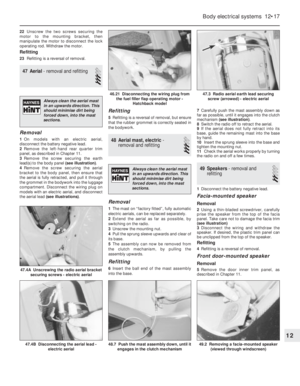 31
31 32
32 33
33 34
34 35
35 36
36 37
37 38
38 39
39 40
40 41
41 42
42 43
43 44
44 45
45 46
46 47
47 48
48 49
49 50
50 51
51 52
52 53
53 54
54 55
55 56
56 57
57 58
58 59
59 60
60 61
61 62
62 63
63 64
64 65
65 66
66 67
67 68
68 69
69 70
70 71
71 72
72 73
73 74
74 75
75 76
76 77
77 78
78 79
79 80
80 81
81 82
82 83
83 84
84 85
85 86
86 87
87 88
88 89
89 90
90 91
91 92
92 93
93 94
94 95
95 96
96 97
97 98
98 99
99 100
100 101
101 102
102 103
103 104
104 105
105 106
106 107
107 108
108 109
109 110
110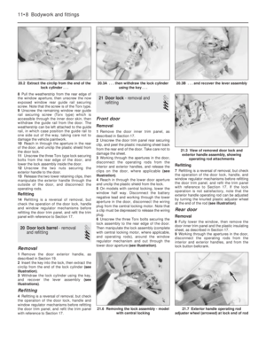 111
111 112
112 113
113 114
114 115
115 116
116 117
117 118
118 119
119 120
120 121
121 122
122 123
123 124
124 125
125 126
126 127
127 128
128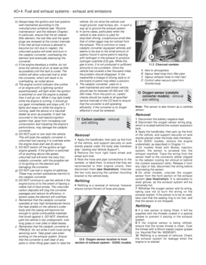 129
129 130
130 131
131 132
132 133
133 134
134 135
135 136
136 137
137 138
138 139
139 140
140 141
141 142
142 143
143 144
144 145
145 146
146 147
147 148
148 149
149 150
150 151
151 152
152 153
153 154
154 155
155 156
156 157
157 158
158 159
159 160
160 161
161 162
162 163
163 164
164 165
165 166
166 167
167 168
168 169
169 170
170 171
171 172
172 173
173 174
174 175
175 176
176 177
177 178
178 179
179 180
180 181
181 182
182 183
183 184
184 185
185 186
186 187
187 188
188 189
189 190
190 191
191 192
192 193
193 194
194 195
195 196
196 197
197 198
198 199
199 200
200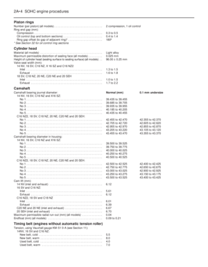 201
201 202
202 203
203 204
204 205
205 206
206 207
207 208
208 209
209 210
210 211
211 212
212 213
213 214
214 215
215 216
216 217
217 218
218 219
219 220
220 221
221 222
222 223
223 224
224 225
225 226
226 227
227 228
228 229
229 230
230 231
231 232
232 233
233 234
234 235
235 236
236 237
237 238
238 239
239 240
240 241
241 242
242 243
243 244
244 245
245 246
246 247
247 248
248 249
249 250
250 251
251 252
252 253
253 254
254 255
255 256
256 257
257 258
258 259
259 260
260 261
261 262
262 263
263 264
264 265
265 266
266 267
267 268
268 269
269 270
270 271
271 272
272 273
273 274
274 275
275 276
276 277
277 278
278 279
279 280
280 281
281 282
282 283
283 284
284 285
285 286
286 287
287 288
288 289
289 290
290 291
291 292
292 293
293 294
294 295
295 296
296 297
297 298
298 299
299 300
300 301
301 302
302 303
303 304
304 305
305 306
306 307
307 308
308 309
309 310
310 311
311 312
312 313
313 314
314 315
315 316
316 317
317 318
318 319
319 320
320 321
321 322
322 323
323 324
324 325
325 326
326 327
327 328
328 329
329 330
330 331
331 332
332 333
333 334
334 335
335 336
336 337
337 338
338 339
339 340
340 341
341 342
342 343
343 344
344 345
345 346
346 347
347 348
348 349
349 350
350 351
351 352
352 353
353 354
354 355
355 356
356 357
357 358
358 359
359 360
360 361
361 362
362 363
363 364
364 365
365 366
366 367
367 368
368 369
369 370
370 371
371 372
372 373
373 374
374 375
375 376
376 377
377 378
378 379
379 380
380 381
381 382
382 383
383 384
384 385
385 386
386 387
387 388
388 389
389 390
390 391
391 392
392 393
393 394
394 395
395 396
396 397
397 398
398 399
399 400
400 401
401 402
402 403
403 404
404 405
405 406
406 407
407 408
408 409
409 410
410 411
411 412
412 413
413 414
414 415
415 416
416 417
417 418
418 419
419 420
420 421
421 422
422 423
423 424
424 425
425 426
426 427
427 428
428 429
429 430
430 431
431 432
432 433
433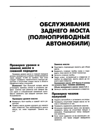 434
434 435
435 436
436 437
437 438
438 439
439 440
440 441
441 442
442 443
443 444
444 445
445 446
446 447
447 448
448 449
449 450
450 451
451 452
452 453
453 454
454 455
455 456
456 457
457 458
458 459
459 460
460 461
461 462
462 463
463 464
464 465
465 466
466 467
467 468
468 469
469 470
470 471
471 472
472 473
473 474
474 475
475 476
476 477
477 478
478 479
479 480
480 481
481 482
482 483
483 484
484 485
485 486
486 487
487 488
488 489
489 490
490 491
491 492
492 493
493 494
494 495
495 496
496 497
497 498
498 499
499 500
500 501
501 502
502 503
503 504
504 505
505 506
506 507
507 508
508 509
509 510
510 511
511 512
512 513
513 514
514 515
515 516
516 517
517 518
518 519
519 520
520 521
521 522
522 523
523 524
524