Page 25 of 525

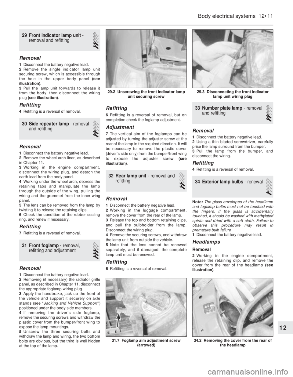
29Front indicator lamp unit -
removal and refitting
2
Removal
1Disconnect the battery negative lead.
2Remove the single indicator lamp unit
securing screw, which is accessible through
the hole in the upper body panel (see
illustration).
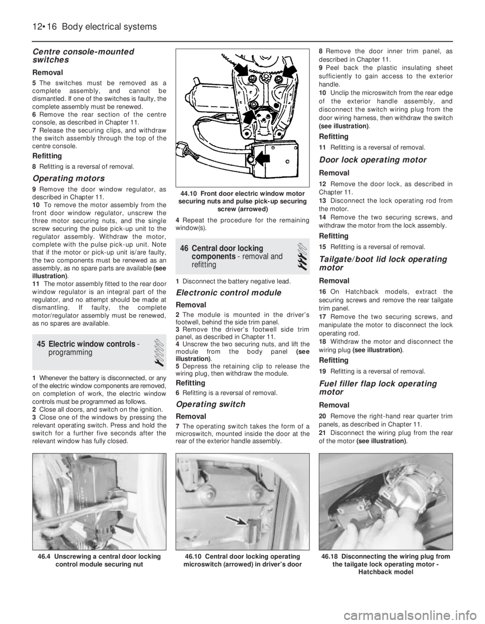
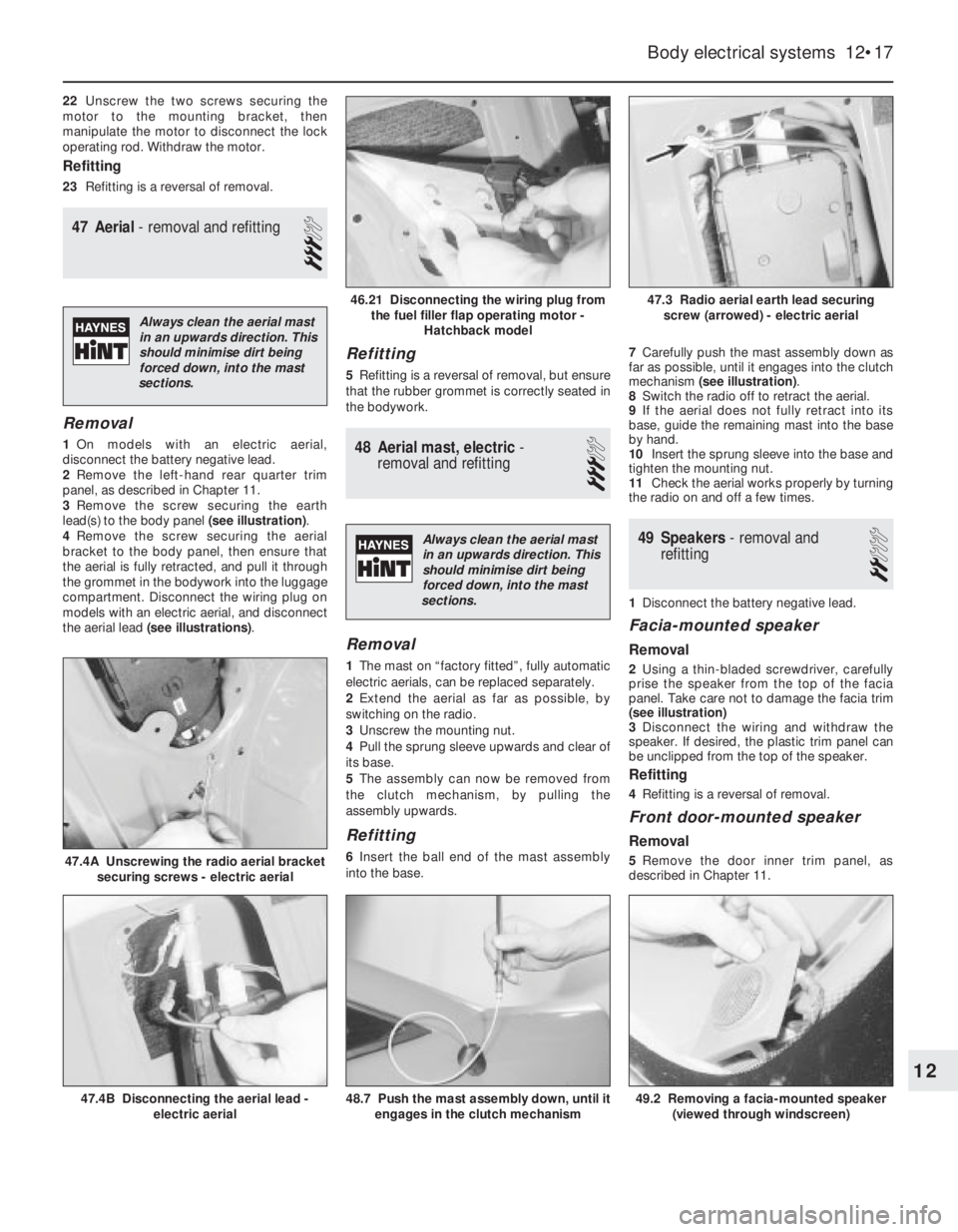
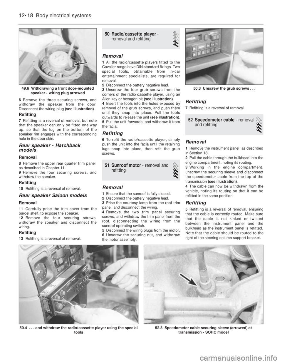
3Pull the lamp unit forwards to release it
from the body, then disconnect the wiring
plug (see illustration).
Refitting
4Refitting is a reversal of removal.
30Side repeater lamp -removal
and refitting
2
Removal
1Disconnect the battery negative lead.
2Remove the wheel arch liner, as described
in Chapter 11.
3Working in the engine compartment,
disconnect the wiring plug, and detach the
earth lead from the body panel.
4Working under the wheel arch, depress the
retaining tabs and manipulate the lamp
through the outside of the wing, pulling the
wiring and the grommet from the inner wing
panel.
5The lens can be removed from the lamp by
twisting it to release the retaining clips.
6Check the condition of the rubber sealing
ring, and renew if necessary.
Refitting
7Refitting is a reversal of removal.
31Front foglamp - removal,
refitting and adjustment
3
Removal
1Disconnect the battery negative lead.
2Removing (if necessary) the radiator grille
panel, as described in Chapter 11, disconnect
the appropriate foglamp wiring plug.
3Apply the handbrake, jack up the front of
the vehicle and support it securely on axle
stands (see “Jacking and Vehicle Support”)
positioned under the body side members.
4If removing the driver’s side foglamp,
remove the securing screws and withdraw the
plastic cover from the bumper/front wing to
expose the lamp mountings.
5Unscrew the three securing bolts and
withdraw the lamp and wiring, the two bottom
bolts are obvious, but the third is well hidden
at the top of the lamp.
Refitting
6Refitting is a reversal of removal, but on
completion check the foglamp adjustment.
Adjustment
7The vertical aim of the foglamps can be
adjusted by turning the adjuster screw at the
rear of the lamp in the required direction. It will
be necessary to remove the plastic cover
(driver’s side only) from the bumper/front wing
to expose the adjuster screw (see
illustration).
32Rear lamp unit - removal and
refitting
2
Removal
1Disconnect the battery negative lead.
2Working in the luggage compartment,
remove the cover from the rear of the lamp.
3Release the top and bottom retaining clips,
and pull the bulbholder from the lamp.
Disconnect the wiring plug.
4Remove the securing screws, and withdraw
the lamp unit from outside the vehicle.
5Note that the lens cannot be renewed
separately, and if damaged, the complete
lamp unit must be renewed.
Refitting
6Refitting is a reversal of removal.
33Number plate lamp -removal
and refitting
2
Removal
1Disconnect the battery negative lead.
2Using a thin-bladed screwdriver, carefully
prise the lamp surround from the bumper.
3Pull the lamp from the bumper, and
disconnect the wiring.
Refitting
4Refitting is a reversal of removal.
34Exterior lamp bulbs - renewal
1
Note: The glass envelopes of the headlamp
and foglamp bulbs must not be touched with
the fingers. If the glass is accidentally
touched, it should be washed with methylated
spirits and dried with a soft cloth. Failure to
observe this procedure may result in
premature bulb failure
1Disconnect the battery negative lead.
Headlamps
Removal
2Working in the engine compartment,
release the retaining clip, and remove the
cover from the rear of the headlamp (see
illustration).
Body electrical systems 12•11
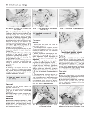
31.7 Foglamp aim adjustment screw
(arrowed)34.2 Removing the cover from the rear of
the headlamp
29.3 Disconnecting the front indicator
lamp unit wiring plug29.2 Unscrewing the front indicator lamp
unit securing screw
12
Page 26 of 525

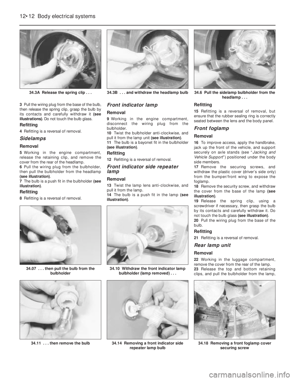
3Pull the wiring plug from the base of the bulb,
then release the spring clip, grasp the bulb by
its contacts and carefully withdraw it (see
illustrations). Do not touch the bulb glass.
Refitting
4Refitting is a reversal of removal.
Sidelamps
Removal
5Working in the engine compartment,
release the retaining clip, and remove the
cover from the rear of the headlamp.
6Pull the wiring plug from the bulbholder,
then pull the bulbholder from the headlamp
(see illustration).
7The bulb is a push fit in the bulbholder (see
illustration).
Refitting
8Refitting is a reversal of removal.
Front indicator lamp
Removal
9Working in the engine compartment,
disconnect the wiring plug from the
bulbholder.
10Twist the bulbholder anti-clockwise, and
pull it from the lamp unit (see illustration).
11The bulb is a bayonet fit in the bulbholder
(see illustration).
Refitting
12Refitting is a reversal of removal.
Front indicator side repeater
lamp
Removal
13Twist the lamp lens anti-clockwise, and
pull it from the lamp.
14The bulb is a push fit in the lamp (see
illustration).
Refitting
15Refitting is a reversal of removal, but
ensure that the rubber sealing ring is correctly
seated between the lens and the body panel.
Front foglamp
Removal
16To improve access, apply the handbrake,
jack up the front of the vehicle, and support
securely on axle stands (see “Jacking and
Vehicle Support”) positioned under the body
side members.
17Remove the securing screws, and
withdraw the plastic cover (driver’s side only)
from the bumper/front wing to expose the
foglamp.
18Remove the security screw, and withdraw
the cover from the base of the lamp (see
illustration).
19Release the spring clip, using a
screwdriver if necessary, then grasp the bulb
by its contacts and carefully withdraw it. Do
not touch the bulb glass (see illustration).
20Pull the wiring plug from the base of the
bulb.
Refitting
21Refitting is a reversal of removal.
Rear lamp unit
Removal
22Working in the luggage compartment,
remove the cover from the rear of the lamp.
23Release the top and bottom retaining
clips, and pull the bulbholder from the lamp,
12•12Body electrical systems
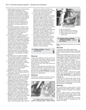
34.3A Release the spring clip . . .34.6 Pull the sidelamp bulbholder from the
headlamp . . .
34.18 Removing a front foglamp cover
securing screw
34.10 Withdraw the front indicator lamp
bulbholder (lamp removed) . . .34.07 . . . then pull the bulb from the
bulbholder
34.14 Removing a front indicator side
repeater lamp bulb34.11 . . . then remove the bulb
34.3B . . . and withdraw the headlamp bulb
Page 27 of 525

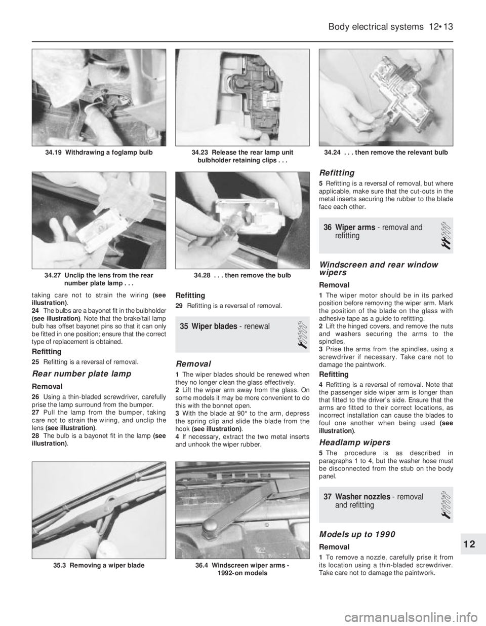
taking care not to strain the wiring (see
illustration).
24The bulbs are a bayonet fit in the bulbholder
(see illustration). Note that the brake/tail lamp
bulb has offset bayonet pins so that it can only
be fitted in one position; ensure that the correct
type of replacement is obtained.
Refitting
25Refitting is a reversal of removal.
Rear number plate lamp
Removal
26Using a thin-bladed screwdriver, carefully
prise the lamp surround from the bumper.
27Pull the lamp from the bumper, taking
care not to strain the wiring, and unclip the
lens (see illustration).
28The bulb is a bayonet fit in the lamp (see
illustration).
Refitting
29Refitting is a reversal of removal.
35Wiper blades -renewal
1
Removal
1The wiper blades should be renewed when
they no longer clean the glass effectively.
2Lift the wiper arm away from the glass. On
some models it may be more convenient to do
this with the bonnet open.
3With the blade at 90°to the arm, depress
the spring clip and slide the blade from the
hook (see illustration).
4If necessary, extract the two metal inserts
and unhook the wiper rubber.
Refitting
5Refitting is a reversal of removal, but where
applicable, make sure that the cut-outs in the
metal inserts securing the rubber to the blade
face each other.
36Wiper arms - removal and
refitting
2
Windscreen and rear window
wipers
Removal
1The wiper motor should be in its parked
position before removing the wiper arm. Mark
the position of the blade on the glass with
adhesive tape as a guide to refitting.
2Lift the hinged covers, and remove the nuts
and washers securing the arms to the
spindles.
3Prise the arms from the spindles, using a
screwdriver if necessary. Take care not to
damage the paintwork.
Refitting
4Refitting is a reversal of removal. Note that
the passenger side wiper arm is longer than
that fitted to the driver’s side. Ensure that the
arms are fitted to their correct locations, as
incorrect installation can cause the blades to
foul one another when being used (see
illustration).
Headlamp wipers
5The procedure is as described in
paragraphs 1 to 4, but the washer hose must
be disconnected from the stub on the body
panel.
37Washer nozzles - removal
and refitting
1
Models up to 1990
Removal
1To remove a nozzle, carefully prise it from
its location using a thin-bladed screwdriver.
Take care not to damage the paintwork.
Body electrical systems 12•13
34.24 . . . then remove the relevant bulb
36.4 Windscreen wiper arms -
1992-on models35.3 Removing a wiper blade
34.28 . . . then remove the bulb34.27 Unclip the lens from the rear
number plate lamp . . .
34.23 Release the rear lamp unit
bulbholder retaining clips . . .34.19 Withdrawing a foglamp bulb
12
Page 28 of 525

2Disconnect the washer hose and withdraw
the nozzle.
Refitting
3To refit, reconnect the washer hose to the
nozzle, and push the nozzle into its locating
hole.
4The nozzles can be adjusted by inserting a
pin into the jet, and swivelling it to the
required position.
1991-on models
5The nozzles on all later models are fitted
with twin jets.
6On some later models, the nozzles are
heated; the circuit is fed through fuse 29 and
is live whenever the ignition is switched on.
Current is regulated by a Positive
Temperature Coefficient (PTC) resistor that
takes outside temperature into account.
38Windscreen wiper motor and
linkage - removal and refitting
3
Removal
1Disconnect the battery negative lead.
2Remove the wiper arms, as described in
Section 36.
3Remove the windscreen cowl panel, as
described in Chapter 11.
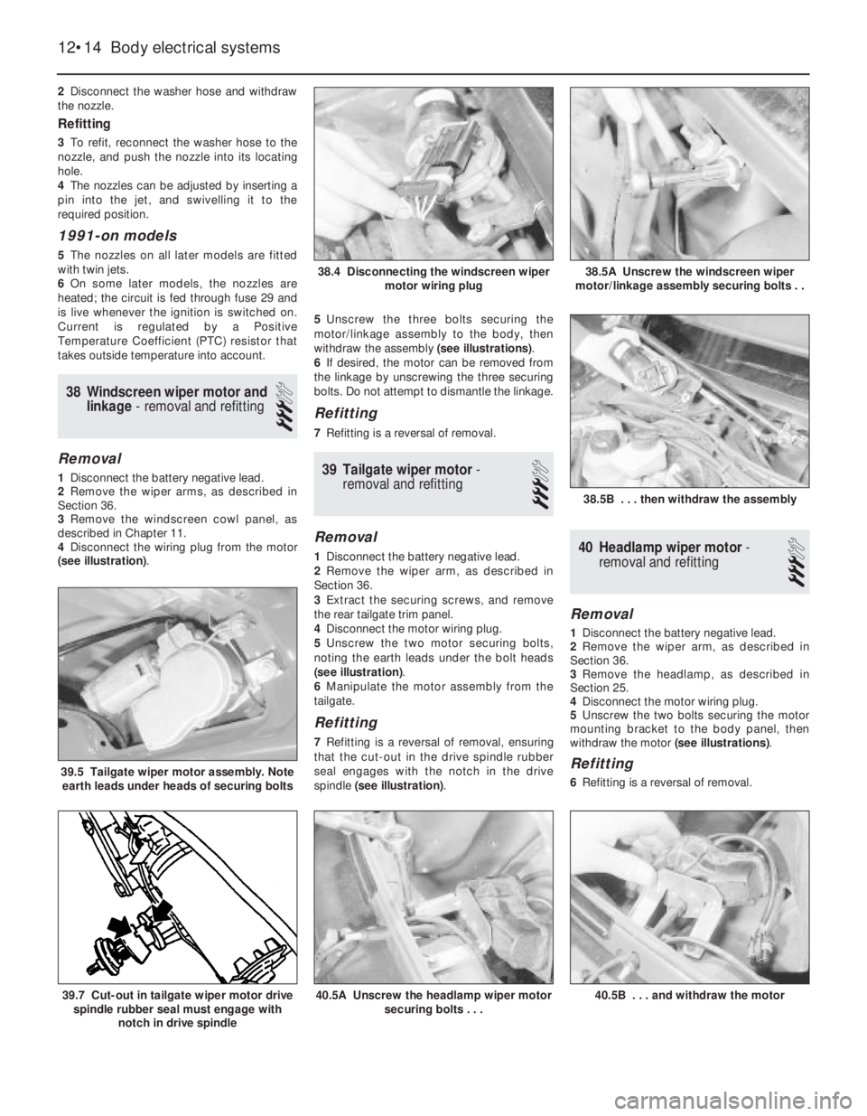
4Disconnect the wiring plug from the motor
(see illustration). 5Unscrew the three bolts securing the
motor/linkage assembly to the body, then
withdraw the assembly (see illustrations).
6If desired, the motor can be removed from
the linkage by unscrewing the three securing
bolts. Do not attempt to dismantle the linkage.
Refitting
7Refitting is a reversal of removal.
39Tailgate wiper motor -
removal and refitting
3
Removal
1Disconnect the battery negative lead.
2Remove the wiper arm, as described in
Section 36.
3Extract the securing screws, and remove
the rear tailgate trim panel.
4Disconnect the motor wiring plug.
5Unscrew the two motor securing bolts,
noting the earth leads under the bolt heads
(see illustration).
6Manipulate the motor assembly from the
tailgate.
Refitting
7Refitting is a reversal of removal, ensuring
that the cut-out in the drive spindle rubber
seal engages with the notch in the drive
spindle (see illustration).
40Headlamp wiper motor -
removal and refitting
3
Removal
1Disconnect the battery negative lead.
2Remove the wiper arm, as described in
Section 36.
3Remove the headlamp, as described in
Section 25.
4Disconnect the motor wiring plug.
5Unscrew the two bolts securing the motor
mounting bracket to the body panel, then
withdraw the motor (see illustrations).
Refitting
6Refitting is a reversal of removal.
12•14Body electrical systems
38.4 Disconnecting the windscreen wiper
motor wiring plug
38.5B . . . then withdraw the assembly
40.5B . . . and withdraw the motor40.5A Unscrew the headlamp wiper motor
securing bolts . . .39.7 Cut-out in tailgate wiper motor drive
spindle rubber seal must engage with
notch in drive spindle
39.5 Tailgate wiper motor assembly. Note
earth leads under heads of securing bolts
38.5A Unscrew the windscreen wiper
motor/linkage assembly securing bolts . .
Page 29 of 525

41Washer fluid reservoir -
removal and refitting
2
1Disconnect the battery negative lead.
Models without headlamp wash
Removal
2Disconnect the wiring from the washer
pump.
3Disconnect the washer fluid hose from the
pump. Be prepared for fluid spillage.
4Remove the screw(s) securing the reservoir
to the body, and withdraw the reservoir.
Refitting
5Refitting is a reversal of removal.
Models with headlamp wash
Removal
6On models with headlamp wash, the
reservoir is in two sections, the upper section,
which can be removed from the engine
compartment, and the lower section, which
must be removed from under the wheel arch.
7Disconnect the wiring from the headlamp
wash non-return valve in the top of the
reservoir.
8Disconnect the washer fluid hoses from the
non-return valve. Be prepared for fluid spillage.
9Remove the screw securing the upper
section of the reservoir to the wing panel.
10Loosen the plastic collar securing the
upper section of the reservoir to the lower
section, then withdraw the upper section of
the reservoir from the engine compartment.
11To remove the lower section of the
reservoir, continue as follows.
12Apply the handbrake, then jack up the
front of the vehicle, and support on axle
stands (see “Jacking and Vehicle Support”)
positioned under the body side members.
13Remove the securing screws, and
withdraw the plastic cover from thebumper/front wing to expose the lower
section of the reservoir.
14Remove the horns, (Section 22).
15Remove the wheel arch liner, (Chapter 11).
16Disconnect the wiring and the fluid hoses
from the washer pump. Be prepared for fluid
spillage.
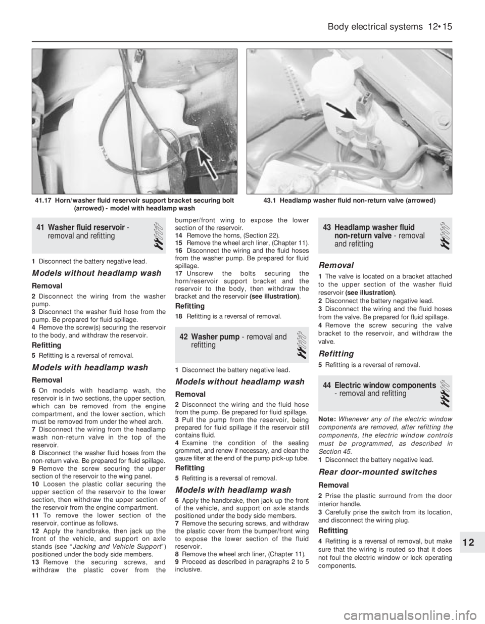
17Unscrew the bolts securing the
horn/reservoir support bracket and the
reservoir to the body, then withdraw the
bracket and the reservoir (see illustration).
Refitting
18Refitting is a reversal of removal.
42Washer pump -removal and
refitting
2
1Disconnect the battery negative lead.
Models without headlamp wash
Removal
2Disconnect the wiring and the fluid hose
from the pump. Be prepared for fluid spillage.
3Pull the pump from the reservoir, being
prepared for fluid spillage if the reservoir still
contains fluid.
4Examine the condition of the sealing
grommet, and renew if necessary, and clean the
gauze filter at the end of the pump pick-up tube.
Refitting
5Refitting is a reversal of removal.
Models with headlamp wash
6Apply the handbrake, then jack up the front
of the vehicle, and support on axle stands
positioned under the body side members.
7Remove the securing screws, and withdraw
the plastic cover from the bumper/front wing
to expose the lower section of the fluid
reservoir.
8Remove the wheel arch liner, (Chapter 11).
9Proceed as described in paragraphs 2 to 5
inclusive.
43Headlamp washer fluid
non-return valve -removal
and refitting
2
Removal
1The valve is located on a bracket attached
to the upper section of the washer fluid
reservoir (see illustration).
2Disconnect the battery negative lead.
3Disconnect the wiring and the fluid hoses
from the valve. Be prepared for fluid spillage.
4Remove the screw securing the valve
bracket to the reservoir, and withdraw the
valve.
Refitting
5Refitting is a reversal of removal.
44Electric window components
- removal and refitting
3
Note: Whenever any of the electric window
components are removed, after refitting the
components, the electric window controls
must be programmed, as described in
Section 45.
1Disconnect the battery negative lead.
Rear door-mounted switches
Removal
2Prise the plastic surround from the door
interior handle.
3Carefully prise the switch from its location,
and disconnect the wiring plug.
Refitting
4Refitting is a reversal of removal, but make
sure that the wiring is routed so that it does
not foul the electric window or lock operating
components.
Body electrical systems 12•15
43.1 Headlamp washer fluid non-return valve (arrowed)41.17 Horn/washer fluid reservoir support bracket securing bolt
(arrowed) - model with headlamp wash
12
Page 30 of 525

Centre console-mounted
switches
Removal
5The switches must be removed as a
complete assembly, and cannot be
dismantled. If one of the switches is faulty, the
complete assembly must be renewed.
6Remove the rear section of the centre
console, as described in Chapter 11.
7Release the securing clips, and withdraw
the switch assembly through the top of the
centre console.
Refitting
8Refitting is a reversal of removal.
Operating motors
9Remove the door window regulator, as
described in Chapter 11.
10To remove the motor assembly from the
front door window regulator, unscrew the
three motor securing nuts, and the single
screw securing the pulse pick-up unit to the
regulator assembly. Withdraw the motor,
complete with the pulse pick-up unit. Note
that if the motor or pick-up unit is/are faulty,
the two components must be renewed as an
assembly, as no spare parts are available (see
illustration).
11The motor assembly fitted to the rear door
window regulator is an integral part of the
regulator, and no attempt should be made at
dismantling. If faulty, the complete
motor/regulator assembly must be renewed,
as no spares are available.
45Electric window controls -
programming
1
1Whenever the battery is disconnected, or any
of the electric window components are removed,
on completion of work, the electric window
controls must be programmed as follows.
2Close all doors, and switch on the ignition.
3Close one of the windows by pressing the
relevant operating switch. Press and hold the
switch for a further five seconds after the
relevant window has fully closed.4Repeat the procedure for the remaining
window(s).
46Central door locking
components -removal and
refitting
3
1Disconnect the battery negative lead.
Electronic control module
Removal
2The module is mounted in the driver’s
footwell, behind the side trim panel.
3Remove the driver’s footwell side trim
panel, as described in Chapter 11.
4Unscrew the two securing nuts, and lift the
module from the body panel (see
illustration).
5Depress the retaining clip to release the
wiring plug, then withdraw the module.
Refitting
6Refitting is a reversal of removal.
Operating switch
Removal
7The operating switch takes the form of a
microswitch, mounted inside the door at the
rear of the exterior handle assembly.8Remove the door inner trim panel, as
described in Chapter 11.
9Peel back the plastic insulating sheet
sufficiently to gain access to the exterior
handle.
10Unclip the microswitch from the rear edge
of the exterior handle assembly, and
disconnect the switch wiring plug from the
door wiring harness, then withdraw the switch
(see illustration).
Refitting
11Refitting is a reversal of removal.
Door lock operating motor
Removal
12Remove the door lock, as described in
Chapter 11.
13Disconnect the lock operating rod from
the motor.
14Remove the two securing screws, and
withdraw the motor from the lock assembly.
Refitting
15Refitting is a reversal of removal.
Tailgate/boot lid lock operating
motor
Removal
16On Hatchback models, extract the
securing screws and remove the rear tailgate
trim panel.
17Remove the two securing screws, and
manipulate the motor to disconnect the lock
operating rod.
18Withdraw the motor and disconnect the
wiring plug (see illustration).
Refitting
19Refitting is a reversal of removal.
Fuel filler flap lock operating
motor
Removal
20Remove the right-hand rear quarter trim
panels, as described in Chapter 11.
21Disconnect the wiring plug from the rear
of the motor (see illustration).
12•16Body electrical systems
44.10 Front door electric window motor
securing nuts and pulse pick-up securing
screw (arrowed)
46.10 Central door locking operating
microswitch (arrowed) in driver’s door46.18 Disconnecting the wiring plug from
the tailgate lock operating motor -
Hatchback model46.4 Unscrewing a central door locking
control module securing nut
Page 31 of 525

22Unscrew the two screws securing the
motor to the mounting bracket, then
manipulate the motor to disconnect the lock
operating rod. Withdraw the motor.
Refitting
23Refitting is a reversal of removal.
47Aerial - removal and refitting
3
Removal
1On models with an electric aerial,
disconnect the battery negative lead.
2Remove the left-hand rear quarter trim
panel, as described in Chapter 11.
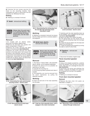
3Remove the screw securing the earth
lead(s) to the body panel (see illustration).
4Remove the screw securing the aerial
bracket to the body panel, then ensure that
the aerial is fully retracted, and pull it through
the grommet in the bodywork into the luggage
compartment. Disconnect the wiring plug on
models with an electric aerial, and disconnect
the aerial lead (see illustrations).
Refitting
5Refitting is a reversal of removal, but ensure
that the rubber grommet is correctly seated in
the bodywork.
48Aerial mast, electric -
removal and refitting
3
Removal
1The mast on “factory fitted”, fully automatic
electric aerials, can be replaced separately.
2Extend the aerial as far as possible, by
switching on the radio.
3Unscrew the mounting nut.
4Pull the sprung sleeve upwards and clear of
its base.
5The assembly can now be removed from
the clutch mechanism, by pulling the
assembly upwards.
Refitting
6Insert the ball end of the mast assembly
into the base.7Carefully push the mast assembly down as
far as possible, until it engages into the clutch
mechanism (see illustration).
8Switch the radio off to retract the aerial.
9If the aerial does not fully retract into its
base, guide the remaining mast into the base
by hand.
10Insert the sprung sleeve into the base and
tighten the mounting nut.
11Check the aerial works properly by turning
the radio on and off a few times.
49Speakers - removal and
refitting
2
1Disconnect the battery negative lead.
Facia-mounted speaker
Removal
2Using a thin-bladed screwdriver, carefully
prise the speaker from the top of the facia
panel. Take care not to damage the facia trim
(see illustration)
3Disconnect the wiring and withdraw the
speaker. If desired, the plastic trim panel can
be unclipped from the top of the speaker.
Refitting
4Refitting is a reversal of removal.
Front door-mounted speaker
Removal
5Remove the door inner trim panel, as
described in Chapter 11.
Body electrical systems 12•17
47.4A Unscrewing the radio aerial bracket
securing screws - electric aerial
49.2 Removing a facia-mounted speaker
(viewed through windscreen)48.7 Push the mast assembly down, until it
engages in the clutch mechanism47.4B Disconnecting the aerial lead -
electric aerial
47.3 Radio aerial earth lead securing
screw (arrowed) - electric aerial46.21 Disconnecting the wiring plug from
the fuel filler flap operating motor -
Hatchback model
12
Always clean the aerial mast
in an upwards direction. This
should minimise dirt being
forced down, into the mast
sections.
Always clean the aerial mast
in an upwards direction. This
should minimise dirt being
forced down, into the mast
sections.
Page 32 of 525

6Remove the three securing screws, and
withdraw the speaker from the door.
Disconnect the wiring plug (see illustration).
Refitting
7Refitting is a reversal of removal, but note
that the speaker can only be fitted one way
up, so that the lug on the bottom of the
speaker rim engages with the corresponding
hole in the door skin.
Rear speaker -Hatchback
models
Removal
8Remove the upper rear quarter trim panel,
as described in Chapter 11.
9Remove the four securing screws, and
withdraw the speaker.
Refitting
10Refitting is a reversal of removal.
Rear speaker Saloon models
Removal
11Carefully prise the trim cover from the
parcel shelf, to expose the speaker.
12Remove the four securing screws,
withdraw the speaker and disconnect the
wiring.
Refitting
13Refitting is a reversal of removal.
50Radio/cassette player -
removal and refitting
2
Removal
1All the radio/cassette players fitted to the
Cavalier range have DIN standard fixings. Two
special tools, obtainable from in-car
entertainment specialists, are required for
removal.
2Disconnect the battery negative lead.
3Unscrew the four grub screws from the
corners of the radio cassette player, using an
Allen key or hexagon bit (see illustration).
4Insert the tools into the holes exposed by
removal of the grub screws, and push them
until they snap into place. Pull the tools
outwards to release the unit (see illustration).
5Pull the unit forwards, and withdraw it from
the facia.
Refitting
6To refit the radio/cassette player, simply
push the unit into the facia until the retaining
lugs snap into place, then refit the grub
screws.
51Sunroof motor - removal and
refitting
3
Removal
1Ensure that the sunroof is fully closed.
2Disconnect the battery negative lead.
3Prise the courtesy lamp from the roof trim
panel, and disconnect the wiring.
4Remove the two trim panel securing
screws, and withdraw the trim panel from the
roof, disconnecting the wiring from the
sunroof operating switch.
5Disconnect the wiring plugs from the motor.
6Unscrew the securing nut, and withdraw
the motor assembly.
Refitting
7Refitting is a reversal of removal.
52Speedometer cable - removal
and refitting
3
Removal
1Remove the instrument panel, as described
in Section 18.
2Pull the cable through the bulkhead into the
engine compartment, noting its routing.
3Working in the engine compartment,
unscrew the securing sleeve and disconnect
the speedometer cable from the top of the
transmission (see illustration).
4The cable can now be withdrawn from the
vehicle, noting its routing so that it can be
refitted in the same position.
Refitting
5Refitting is a reversal of removal, ensuring
that the cable is correctly routed. Make sure
that the cable is not kinked or twisted
between the instrument panel and the
bulkhead as the instrument panel is refitted.
Note that the cable should be routed to the
right of the steering column support bracket.
12•18Body electrical systems
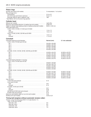
49.6 Withdrawing a front door-mounted
speaker - wiring plug arrowed
50.4 . . . and withdraw the radio/cassette player using the special
tools52.3 Speedometer cable securing sleeve (arrowed) at
transmission - SOHC model
50.3 Unscrew the grub screws . . .