Page 177 of 525
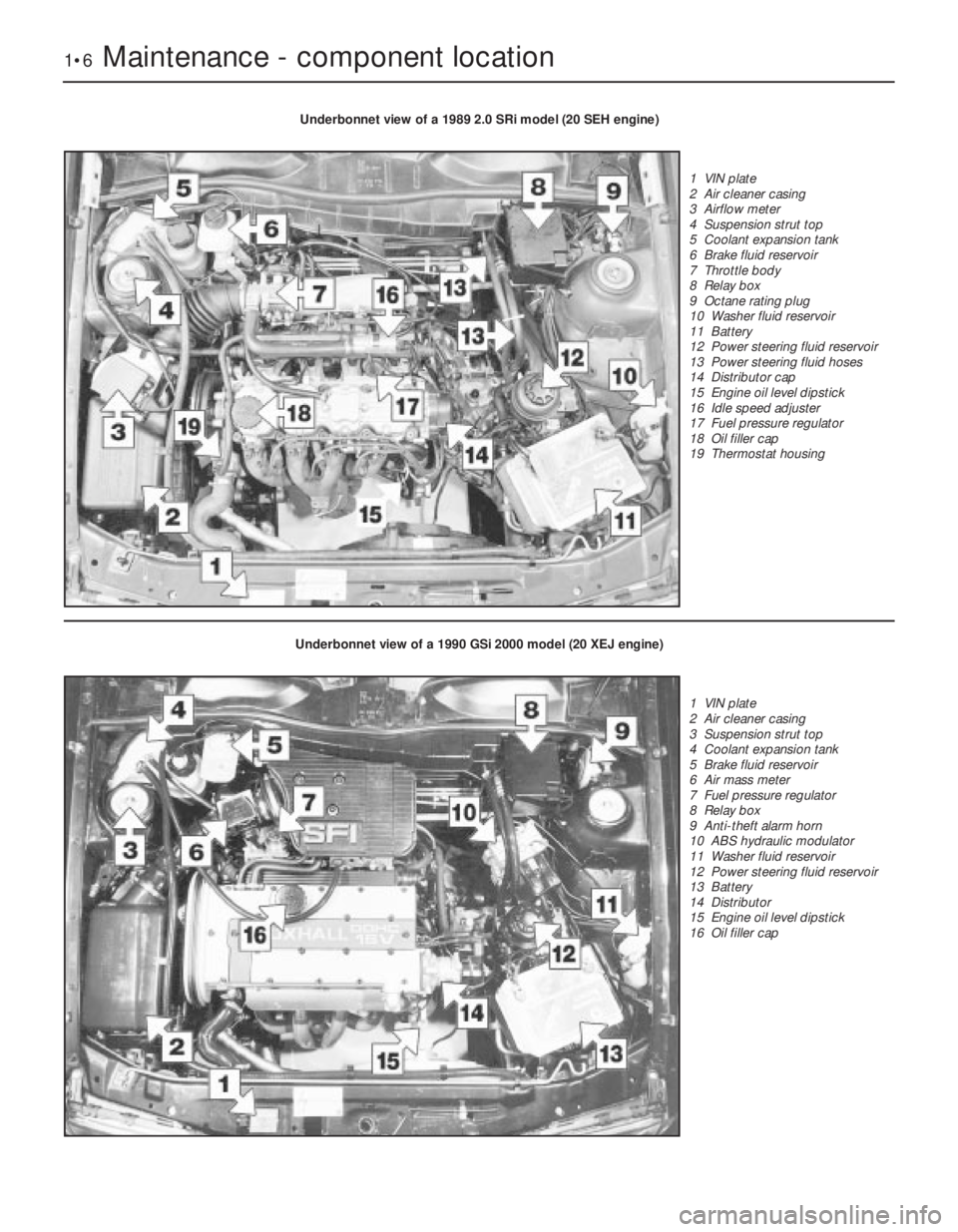
1•6Maintenance - component location
Underbonnet view of a 1989 2.0 SRi model (20 SEH engine)
1 VIN plate
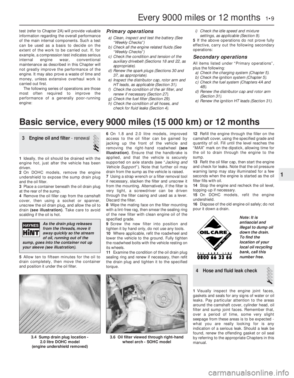
2 Air cleaner casing
3 Airflow meter
4 Suspension strut top
5 Coolant expansion tank
6 Brake fluid reservoir
7 Throttle body
8 Relay box
9 Octane rating plug
10 Washer fluid reservoir
11 Battery
12 Power steering fluid reservoir
13 Power steering fluid hoses
14 Distributor cap
15 Engine oil level dipstick
16 Idle speed adjuster
17 Fuel pressure regulator
18 Oil filler cap
19 Thermostat housing
Underbonnet view of a 1990 GSi 2000 model (20 XEJ engine)
1 VIN plate
2 Air cleaner casing
3 Suspension strut top
4 Coolant expansion tank
5 Brake fluid reservoir
6 Air mass meter
7 Fuel pressure regulator
8 Relay box
9 Anti-theft alarm horn
10 ABS hydraulic modulator
11 Washer fluid reservoir
12 Power steering fluid reservoir
13 Battery
14 Distributor
15 Engine oil level dipstick
16 Oil filler cap
Page 178 of 525
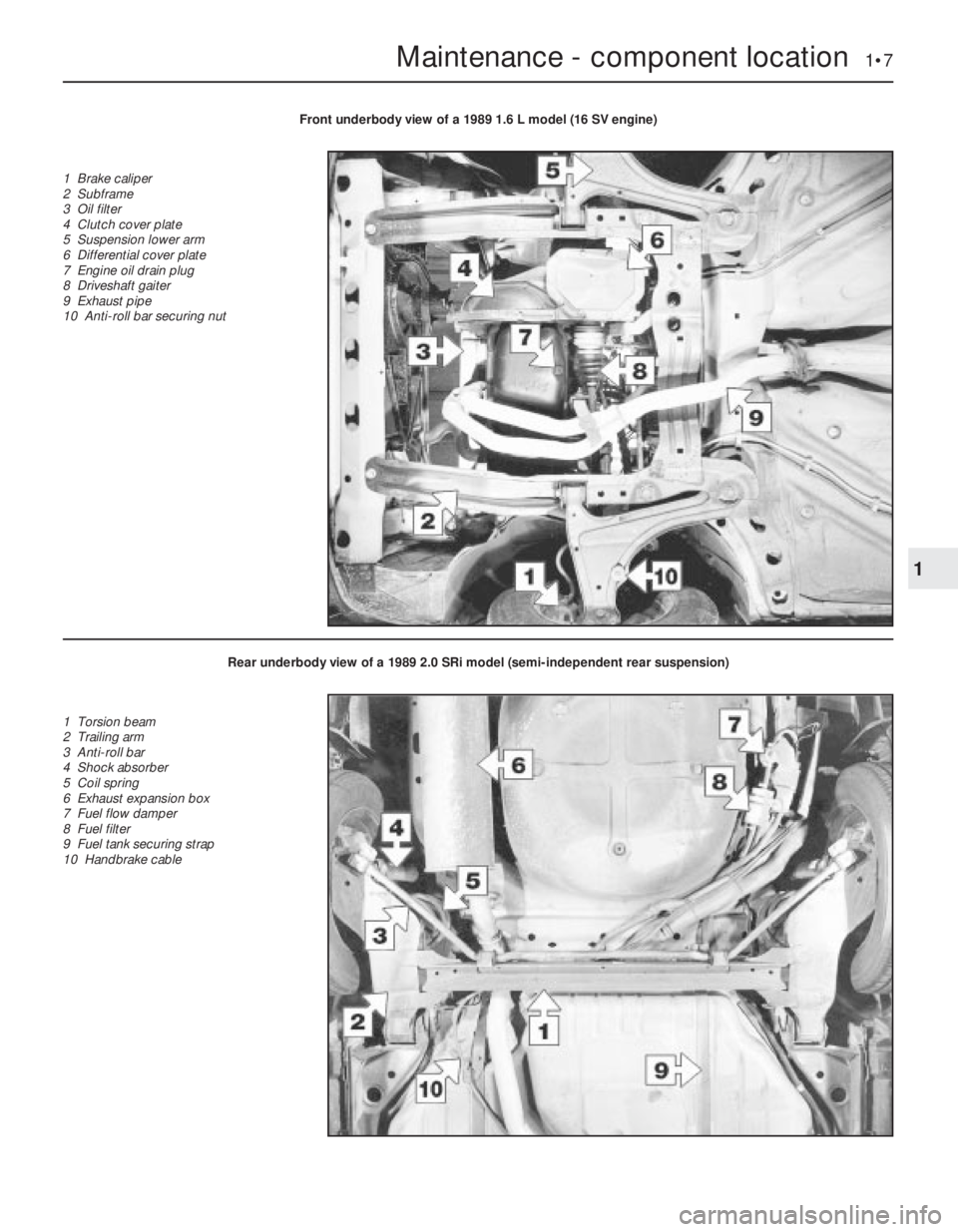
Maintenance - component location 1•7
1
Front underbody view of a 1989 1.6 L model (16 SV engine)
1 Brake caliper
2 Subframe
3 Oil filter
4 Clutch cover plate
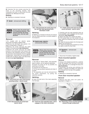
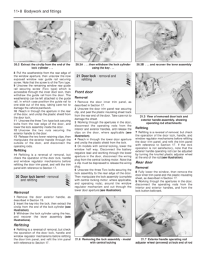
5 Suspension lower arm
6 Differential cover plate
7 Engine oil drain plug
8 Driveshaft gaiter
9 Exhaust pipe
10 Anti-roll bar securing nut
Rear underbody view of a 1989 2.0 SRi model (semi-independent rear suspension)
1 Torsion beam
2 Trailing arm
3 Anti-roll bar
4 Shock absorber
5 Coil spring
6 Exhaust expansion box
7 Fuel flow damper
8 Fuel filter
9 Fuel tank securing strap
10 Handbrake cable
Page 179 of 525

1Introduction
This Chapter is designed to help the home
mechanic maintain his/her vehicle for safety,
economy, long life and peak performance.
The Chapter contains a master maintenance
schedule, followed by Sections dealing specifically
with each task in the schedule. Visual checks,
adjustments, component renewal and other helpful
items are included. Refer to the accompanying
illustrations of the engine compartment and the
underside of the vehicle for the locations of the
various components.
Servicing your vehicle according to the
mileage/time maintenance schedule and the
following Sections will provide a planned
maintenance programme, which should result in a
long and reliable service life. This is a comprehensiveplan, so maintaining some items but not others at
the specified service intervals, will not produce the
same results.
As you service your vehicle, you will
discover that many of the procedures can -
and should - be grouped together, because of
the particular procedure being performed, or
because of the proximity of two otherwise-
unrelated components to one another. For
example, if the vehicle is raised for any
reason, the exhaust can be inspected at the
same time as the suspension and steering
components.
The first step in this maintenance
programme is to prepare yourself before the
actual work begins. Read through all the
Sections relevant to the work to be carried
out, then make a list and gather all the parts
and tools required. If a problem is found, seek
advice from a parts specialist, or a dealer
service department.
2Intensive maintenance
If, from the time the vehicle is new, routine
maintenance schedule is followed closely,
frequent checks made of fluid levels and high-
wear items, as recommended, the engine will
be kept in relatively good running condition.
The need for additional work will be minimised
It is possible that there will be times when
the engine is running poorly due to the lack of
regular maintenance. This is even more likely
if a used vehicle, which has not received
regular and frequent maintenance checks, is
purchased. In such cases, additional work
may need to be carried out, outside of the
regular maintenance intervals.
If engine wear is suspected, a compression
1•8Maintenance - component location
Rear underbody view of a 1990 GSi 2000 model (fully independent rear suspension)
1 Fuel tank securing strap
2 Shock absorber
3 ABS wheel sensor
4 Semi-trailing arm
5 Suspension crossmember
mounting bracing bracket
6 Handbrake cable
7 Suspension crossmember
8 Exhaust expansion box
9 Fuel pump
Maintenance procedures
Page 180 of 525

test (refer to Chapter 2A) will provide valuable
information regarding the overall performance
of the main internal components. Such a test
can be used as a basis to decide on the
extent of the work to be carried out. If, for
example, a compression test indicates serious
internal engine wear, conventional
maintenance as described in this Chapter will
not greatly improve the performance of the
engine. It may also prove a waste of time and
money, unless extensive overhaul work is
carried out first.
The following series of operations are those
most often required to improve the
performance of a generally poor-running
engine:Primary operations
a)Clean, inspect and test the battery (See
“Weekly Checks”)
b)Check all the engine related fluids (See
“Weekly Checks”)
c)Check the condition and tension of the
auxiliary drivebelt (Sections 18 and 22, as
appropriate).
d)Renew the spark plugs (Sections 30 and
37, as appropriate).
e)Inspect the distributor cap, rotor arm and
HT leads, as applicable (Section 31).
f)Check the condition of the air filter, and
renew if necessary (Section 27).
g)Check the fuel filter (Section 29).
h)Check the condition of all hoses, and
check for fluid leaks (Section 4).i)Check the idle speed and mixture
settings, as applicable (Section 9).
5If the above operations do not prove fully
effective, carry out the following secondary
operations:
Secondary operations
All items listed under “Primary operations”,
plus the following:
a)Check the charging system (Chapter 5).
b)Check the ignition system (Chapter 5).
c)Check the fuel system (Chapters 4A and
4B).
d)Renew the distributor cap and rotor arm
(Section 31).
e)Renew the ignition HT leads (Section 31).
3Engine oil and filter - renewal
2
1Ideally, the oil should be drained with the
engine hot, just after the vehicle has been
driven.
2On DOHC models, remove the engine
undershield to expose the sump drain plug
and the oil filter.
3Place a container beneath the oil drain plug
at the rear of the sump.
4Remove the oil filler cap from the camshaft
cover, then using a socket or spanner,
unscrew the oil drain plug, and allow the oil to
drain (see illustration). Take care to avoid
scalding if the oil is hot.
5Allow ten to fifteen minutes for the oil to
drain completely, then move the container
and position it under the oil filter.6On 1.8 and 2.0 litre models, improved
access to the oil filter can be gained by
jacking up the front of the vehicle and
removing the right-hand roadwheel (see
illustration). Ensure that the handbrake is
applied, and that the vehicle is securely
supported on axle stands (see “Jacking and
Vehicle Support”). Note that further oil may
drain from the sump as the vehicle is raised.
7Using a strap wrench or a filter removal tool
if necessary, slacken the filter and unscrew it
from the mounting. Alternatively, if the filter is
very tight, a screwdriver can be driven
through the filter casing and used as a lever.
Discard the filter.
8Wipe the mating face on the filter mounting
with a lint-free rag, then smear the sealing ring
of the new filter with clean engine oil of the
specified grade.
9Screw the new filter into position and
tighten it by hand only, do not use any tools.
10Where applicable, refit the roadwheel and
lower the vehicle to the ground. Fully tighten
the roadwheel bolts with the vehicle resting on
its wheels.
11Examine the condition of the oil drain plug
sealing ring and renew if necessary, then refit
the drain plug and tighten it to the specified
torque. 12Refill the engine through the filler on the
camshaft cover, using the specified grade and
quantity of oil. Fill until the level reaches the
“MAX” mark on the dipstick, allowing time for
the oil to drain through the engine to the
sump.
13Refit the oil filler cap, then start the engine
and check for leaks. Note that the oil pressure
warning lamp may stay illuminated for a few
seconds when the engine is started as the oil
filter fills with oil.
14Stop the engine and recheck the oil level,
topping-up if necessary.
15On DOHC models, refit the engine
undershield.
16Dispose of the old engine oil safely; do not
pour it down a drain.
4Hose and fluid leak check
1
1Visually inspect the engine joint faces,
gaskets and seals for any signs of water or oil
leaks. Pay particular attention to the areas
around the camshaft cover, cylinder head, oil
filter and sump joint faces. Remember that,
over a period of time, some very slight
seepage from these areas is to be expected -
what you are really looking for is any
indication of a serious leak. Should a leak be
found, renew the offending gasket or oil seal
by referring to the appropriate Chapters in this
manual.
Every 9000 miles or 12 months 1•9
3.6 Oil filter viewed through right-hand
wheel arch - SOHC model3.4 Sump drain plug location -
2.0 litre DOHC model
(engine undershield removed)
1
Basic service, every 9000 miles (15 000 km) or 12 months
As the drain plug releases
from the threads, move it
away quickly so the stream
of oil, running out of the
sump, goes into the container not up
your sleeve (see illustration).
Note: It is
antisocial and
illegal to dump oil
down the drain.
To find the
location of your
local oil recycling
bank, call this
number free.
Page 181 of 525

2Also check the security and condition of all
the engine related pipes and hoses. Ensure
that all cable-ties or securing clips are in
place, and in good condition. Clips that are
broken or missing can lead to chafing of the
hoses, pipes or wiring, which could cause
more serious problems in the future.
3Carefully check the radiator hoses and
heater hoses along their entire length. Renew
any hose that is cracked, swollen or
deteriorated. Cracks will show up better if the
hose is squeezed. Pay close attention to the
hose clips that secure the hoses to the
cooling system components. Hose clips can
pinch and puncture hoses, resulting in cooling
system leaks. It is always beneficial to renew
hose clips whenever possible.
4Inspect all the cooling system components
(hoses, joint faces, etc.) for leaks.
5Where any problems are found on system
components, renew the component or gasket
with reference to Chapter 3.
6Where applicable, inspect the automatic
transmission fluid cooler hoses for leaks or
deterioration.
7With the vehicle raised, inspect the petrol
tank and filler neck for punctures, cracks and
other damage. The connection between the
filler neck and tank is especially critical.
Sometimes a rubber filler neck or connecting
hose will leak due to loose retaining clamps or
deteriorated rubber.
8Carefully check all rubber hoses and metal
fuel lines leading away from the petrol tank.
Check for loose connections, deteriorated
hoses, crimped lines, and other damage. Pay
particular attention to the vent pipes and
hoses, which often loop up around the filler
neck and can become blocked or crimped.
Follow the lines to the front of the vehicle,
carefully inspecting them all the way. Renew
damaged sections as necessary.
9From within the engine compartment,
check the security of all fuel hose attachments
and pipe unions, and inspect the fuel hoses
and vacuum hoses for kinks, chafing and
deterioration.
10Where applicable, check the condition of
the power steering fluid hoses and pipes.5Steering and suspension
check
2
Front suspension and steering
check
1Raise the front of the car, and support on
axle stands (“Jacking and Vehicle Support”).
2Visually inspect the balljoint dust covers
and the steering rack-and-pinion gaiters for
splits, chafing or deterioration. Any wear of
these components will cause loss of lubricant,
together with dirt and water entry, resulting in
rapid wear of the balljoints or steering gear.
3On vehicles with power steering, check the
fluid hoses for chafing or deterioration, and
the pipe and hose unions for fluid leaks. Also
check for signs of fluid leakage under
pressure from the steering gear rubber
gaiters, which would indicate failed fluid seals
within the steering gear.
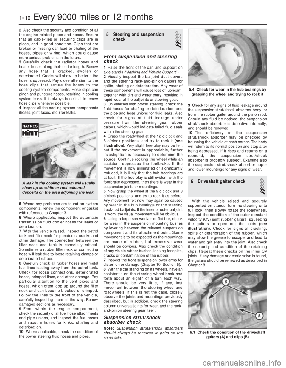
4Grasp the roadwheel at the 12 o’clock and
6 o’clock positions, and try to rock it (see
illustration). Very slight free play may be felt,
but if the movement is appreciable, further
investigation is necessary to determine the
source. Continue rocking the wheel while an
assistant depresses the footbrake. If the
movement is now eliminated or significantly
reduced, it is likely that the hub bearings are
at fault. If the free play is still evident with the
footbrake depressed, then there is wear in the
suspension joints or mountings.
5Now grasp the wheel at the 9 o’clock and 3
o’clock positions, and try to rock it as before.
Any movement felt now may again be caused
by wear in the hub bearings or the steering
track-rod balljoints. If the inner or outer balljoint
is worn, the visual movement will be obvious.
6Using a large screwdriver or flat bar, check
for wear in the suspension mounting bushes
by levering between the relevant suspension
component and its attachment point. Some
movement is to be expected as the mountings
are made of rubber, but excessive wear
should be obvious. Also check the condition
of any visible rubber bushes, looking for splits,
cracks or contamination of the rubber.
7Inspect the front suspension lower arms for
distortion or damage (Chapter 10, Section 5).
8With the car standing on its wheels, have an
assistant turn the steering wheel back and
forth about an eighth of a turn each way.
There should be very little, if any, lost
movement between the steering wheel and
roadwheels. If this is not the case, closely
observe the joints and mountings previously
described, but in addition, check the steering
column universal joints for wear, and the rack-
and-pinion steering gear itself.
Suspension strut/shock
absorber check
Note:Suspension struts/shock absorbers
should always be renewed in pairs on the
same axle.9Check for any signs of fluid leakage around
the suspension strut/shock absorber body, or
from the rubber gaiter around the piston rod.
Should any fluid be noticed, the suspension
strut/shock absorber is defective internally,
and should be renewed.
10The efficiency of the suspension
strut/shock absorber may be checked by
bouncing the vehicle at each corner. The body
will return to its normal position and stop after
being depressed. If it rises and returns on a
rebound, the suspension strut/shock
absorber is probably suspect. Examine also
the suspension strut/shock absorber upper
and lower mountings for any signs of wear.
6Driveshaft gaiter check
2
With the vehicle raised and securely
supported on stands, turn the steering onto
full lock, then slowly rotate the roadwheel.
Inspect the condition of the outer constant
velocity (CV) joint rubber gaiters, squeezing
the gaiters to open out the folds (see
illustration). Check for signs of cracking,
splits or deterioration of the rubber, which
may allow the grease to escape, and lead to
water and grit entry into the joint. Also check
the security and condition of the retaining
clips. Repeat these checks on the inner CV
joints. If any damage or deterioration is found,
the gaiters should be renewed as described in
Chapter 8.
1•10Every 9000 miles or 12 months
6.1 Check the condition of the driveshaft
gaiters (A) and clips (B)
5.4 Check for wear in the hub bearings by
grasping the wheel and trying to rock it
A leak in the cooling system will usually
show up as white or rust coloured
deposits on the area adjoining the leak
Page 182 of 525

At the same time, check the general
condition of the CV joints themselves by first
holding the driveshaft and attempting to
rotate the wheel. Repeat this check by holding
the inner joint and attempting to rotate the
driveshaft. Any appreciable movement
indicates wear in the joints, wear in the
driveshaft splines, or a loose driveshaft
retaining nut.
7Automatic transmission fluid
level check
2
Note: The transmission fluid level can be
checked either when it is cold (only below
35ºC (100ºF) outside temperature) or when it is
fully warmed up to normal operating
temperature (after driving for a distance of
approximately 12 miles/20 km). Since the fluid
level must be checked with the engine
running, ensure that the vehicle is parked on
level ground with the handbrake firmly applied
before leaving the driver’s seat. Be careful to
keep loose clothing, long hair, etc., well clear
of hot or moving components when working
under the bonnet
Transmission cold
1Park the vehicle on level ground and apply
the handbrake firmly. With the engine running
at no more than idle speed and your foot
firmly on the brake pedal, move the selector
lever through all positions, ending in position
“P”. Allow the engine to idle for one minute,
then check the level within two minutes.
2With the engine still idling and position “P”
still selected, open the bonnet and withdraw
the transmission dipstick from the filler tube
located in the front of the transmission casing,
at the left-hand end of the engine.
3Note the fluid’s condition (see below), then
wipe clean the dipstick using a clean,
non-fluffy rag, insert it fully back into the tube
and withdraw it again.
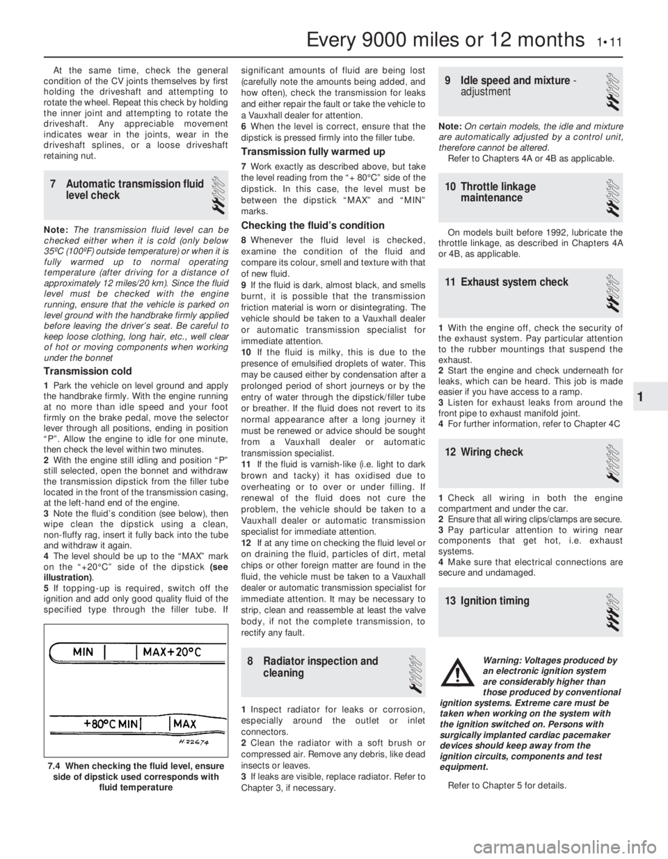
4The level should be up to the “MAX” mark
on the “+20°C” side of the dipstick (see
illustration).
5If topping-up is required, switch off the
ignition and add only good quality fluid of the
specified type through the filler tube. Ifsignificant amounts of fluid are being lost
(carefully note the amounts being added, and
how often), check the transmission for leaks
and either repair the fault or take the vehicle to
a Vauxhall dealer for attention.
6When the level is correct, ensure that the
dipstick is pressed firmly into the filler tube.
Transmission fully warmed up
7Work exactly as described above, but take
the level reading from the “+ 80°C” side of the
dipstick. In this case, the level must be
between the dipstick “MAX” and “MIN”
marks.
Checking the fluid’s condition
8Whenever the fluid level is checked,
examine the condition of the fluid and
compare its colour, smell and texture with that
of new fluid.
9If the fluid is dark, almost black, and smells
burnt, it is possible that the transmission
friction material is worn or disintegrating. The
vehicle should be taken to a Vauxhall dealer
or automatic transmission specialist for
immediate attention.
10If the fluid is milky, this is due to the
presence of emulsified droplets of water. This
may be caused either by condensation after a
prolonged period of short journeys or by the
entry of water through the dipstick/filler tube
or breather. If the fluid does not revert to its
normal appearance after a long journey it
must be renewed or advice should be sought
from a Vauxhall dealer or automatic
transmission specialist.
11If the fluid is varnish-like (i.e. light to dark
brown and tacky) it has oxidised due to
overheating or to over or under filling. If
renewal of the fluid does not cure the
problem, the vehicle should be taken to a
Vauxhall dealer or automatic transmission
specialist for immediate attention.
12If at any time on checking the fluid level or
on draining the fluid, particles of dirt, metal
chips or other foreign matter are found in the
fluid, the vehicle must be taken to a Vauxhall
dealer or automatic transmission specialist for
immediate attention. It may be necessary to
strip, clean and reassemble at least the valve
body, if not the complete transmission, to
rectify any fault.
8Radiator inspection and
cleaning
1
1Inspect radiator for leaks or corrosion,
especially around the outlet or inlet
connectors.
2Clean the radiator with a soft brush or
compressed air. Remove any debris, like dead
insects or leaves.
3If leaks are visible, replace radiator. Refer to
Chapter 3, if necessary.
9Idle speed and mixture -
adjustment
2
Note: On certain models, the idle and mixture
are automatically adjusted by a control unit,
therefore cannot be altered.
Refer to Chapters 4A or 4B as applicable.
10Throttle linkage
maintenance
2
On models built before 1992, lubricate the
throttle linkage, as described in Chapters 4A
or 4B, as applicable.
11Exhaust system check
2
1With the engine off, check the security of
the exhaust system. Pay particular attention
to the rubber mountings that suspend the
exhaust.
2Start the engine and check underneath for
leaks, which can be heard. This job is made
easier if you have access to a ramp.
3Listen for exhaust leaks from around the
front pipe to exhaust manifold joint.
4For further information, refer to Chapter 4C
12Wiring check
1
1Check all wiring in both the engine
compartment and under the car.
2Ensure that all wiring clips/clamps are secure.
3Pay particular attention to wiring near
components that get hot, i.e. exhaust
systems.
4Make sure that electrical connections are
secure and undamaged.
13Ignition timing
3
Refer to Chapter 5 for details.
Every 9000 miles or 12 months 1•11
7.4 When checking the fluid level, ensure
side of dipstick used corresponds with
fluid temperature
1
Warning: Voltages produced by
an electronic ignition system
are considerably higher than
those produced by conventional
ignition systems. Extreme care must be
taken when working on the system with
the ignition switched on. Persons with
surgically implanted cardiac pacemaker
devices should keep away from the
ignition circuits, components and test
equipment.
Page 183 of 525

14Brake fluid renewal
3
Renew the brake and bleed the system.
Refer to Chapter 9 for full details.
15Brake pad check
2
With the front or rear (as applicable) of the
vehicle raised, remove the wheels and check
brake pads for wear. Renew the pads if the
lining is below that specified. See Chapter 9,
for specifications and full details.
16Handbrake linkage check
2
With the vehicle raised, check the operation
of the handbrake and lubricate the linkages.
Refer to Chapter 9, for further details.
17Power steering fluid check
2
1With the engine off, remove the cap from
the power steering reservoir. It is fitted with a
dipstick.
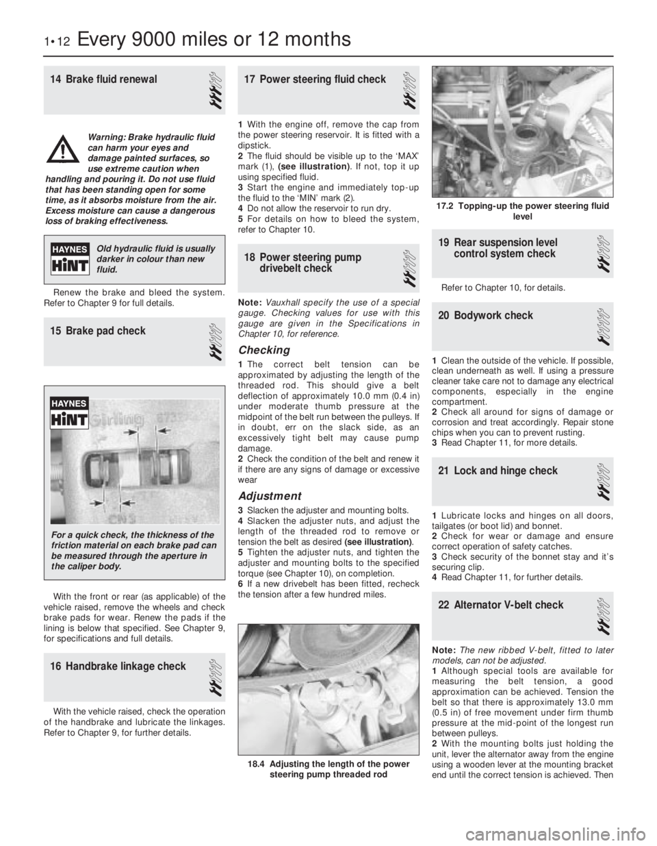
2The fluid should be visible up to the ‘MAX’
mark (1), (see illustration). If not, top it up
using specified fluid.
3Start the engine and immediately top-up
the fluid to the ‘MIN’ mark (2).
4Do not allow the reservoir to run dry.
5For details on how to bleed the system,
refer to Chapter 10.
18Power steering pump
drivebelt check
2
Note:Vauxhall specify the use of a special
gauge. Checking values for use with this
gauge are given in the Specifications in
Chapter 10, for reference.
Checking
1The correct belt tension can be
approximated by adjusting the length of the
threaded rod. This should give a belt
deflection of approximately 10.0 mm (0.4 in)
under moderate thumb pressure at the
midpoint of the belt run between the pulleys. If
in doubt, err on the slack side, as an
excessively tight belt may cause pump
damage.
2Check the condition of the belt and renew it
if there are any signs of damage or excessive
wear
Adjustment
3Slacken the adjuster and mounting bolts.
4Slacken the adjuster nuts, and adjust the
length of the threaded rod to remove or
tension the belt as desired (see illustration).
5Tighten the adjuster nuts, and tighten the
adjuster and mounting bolts to the specified
torque (see Chapter 10), on completion.
6If a new drivebelt has been fitted, recheck
the tension after a few hundred miles.
19Rear suspension level
control system check
2
Refer to Chapter 10, for details.
20Bodywork check
1
1Clean the outside of the vehicle. If possible,
clean underneath as well. If using a pressure
cleaner take care not to damage any electrical
components, especially in the engine
compartment.
2Check all around for signs of damage or
corrosion and treat accordingly. Repair stone
chips when you can to prevent rusting.
3Read Chapter 11, for more details.
21Lock and hinge check
2
1Lubricate locks and hinges on all doors,
tailgates (or boot lid) and bonnet.
2Check for wear or damage and ensure
correct operation of safety catches.
3Check security of the bonnet stay and it’s
securing clip.
4Read Chapter 11, for further details.
22Alternator V-belt check
2
Note:The new ribbed V-belt, fitted to later
models, can not be adjusted.
1Although special tools are available for
measuring the belt tension, a good
approximation can be achieved. Tension the
belt so that there is approximately 13.0 mm
(0.5 in) of free movement under firm thumb
pressure at the mid-point of the longest run
between pulleys.
2With the mounting bolts just holding the
unit, lever the alternator away from the engine
using a wooden lever at the mounting bracket
end until the correct tension is achieved. Then
1•12Every 9000 miles or 12 months
17.2 Topping-up the power steering fluid
level
18.4 Adjusting the length of the power
steering pump threaded rod
Warning: Brake hydraulic fluid
can harm your eyes and
damage painted surfaces, so
use extreme caution when
handling and pouring it. Do not use fluid
that has been standing open for some
time, as it absorbs moisture from the air.
Excess moisture can cause a dangerous
loss of braking effectiveness.
Old hydraulic fluid is usually
darker in colour than new
fluid.
For a quick check, the thickness of the
friction material on each brake pad can
be measured through the aperture in
the caliper body.
Page 184 of 525

tighten the mounting nuts and bolts. On no
account lever at the free end of the alternator,
as serious internal damage could be caused.
3For details of replacement, see Chapter 5.
23Headlamp alignment
2
Refer to Chapter 12 for details.
24Door lock key battery -
replacement
1
1Carefully prise open the outer cover from
the key. Take care not to lose any of the
internal components, as they are loose.
2Remove the battery and discard it safely.
3Place the new battery, “+” side up (see
illustration). Check the operation of the key. If
the bulb does not light obtain a replacement.
4Replace the outer cover.
25Road test
1
Instruments and electrical
equipment
1Check the operation of all instruments and
electrical equipment.
2Make sure that all instruments read
correctly, and switch on all electrical
equipment in turn to check that it functions
properly.
Steering and suspension
3Check for any abnormalities in the steering,
suspension, handling or road “feel”.
4Drive the vehicle, and check that there are
no unusual vibrations or noises.5Check that the steering feels positive, with
no excessive “sloppiness”, or roughness, and
check for any suspension noises when
cornering, or when driving over bumps.
Drivetrain
6Check the performance of the engine,
clutch, transmission and driveshafts.
7Turn the radio/cassette off and listen for
any unusual noises from the engine, clutch
and transmission.
8Make sure that the engine runs smoothly
when idling, and that there is no hesitation
when accelerating.
9Check that the clutch action is smooth and
progressive, that the drive is taken up
smoothly, and that the pedal travel is not
excessive. Also listen for any noises when the
clutch pedal is depressed.
10Check that all gears can be engaged
smoothly, without noise, and that the gear
lever action is not abnormally vague or
“notchy”.
11Listen for a metallic clicking sound from
the front of the vehicle, as the vehicle is driven
slowly in a circle with the steering on full lock.
Carry out this check in both directions. If a
clicking noise is heard, this indicates wear in a
driveshaft joint, in which case, the complete
driveshaft must be renewed (see Chapter 8).
26Coolant renewal
2
Refer to Chapter 3 for details.
27Air cleaner element - renewal
2
Early round type
1Release the spring clips from the perimeter
of the air cleaner cover.
2Unscrew and remove the small cross-head
screw securing the cover extension to the
main body near the inlet duct.3Unscrew and remove the three central
cross-head cap nuts securing the air cleaner
to the carburettor, taking care not to drop the
washers and seals (see illustration).
4Separate the cover from the main body,
then lift out the element (see illustration).
5Wipe clean the inside surfaces of the cover
and main body.
6Locate the new element in the air cleaner
body, and refit the cover using a reversal of
the removal procedure.
Square type with air box
7If desired, to improve access, unclip the
coolant expansion tank hose from the air
cleaner cover.
8Release the two clips from the left-hand
side of the cover, and unscrew the two
screws from the right-hand side, then lift the
cover sufficiently to remove the element.
9Wipe clean the inside surfaces of the cover
and main body.
10Refitting is a reversal of removal, noting
that the element fits with the rubber locating
flange uppermost.
Every 18 000 miles or 24 months 1•13
24.3 Replacing the battery in the door lock
key
1 Battery (note, positive ‘+’ side up)
2 Bulb
27.4 Removing the air cleaner element -
note clip for crankcase ventilation hose
(arrowed)
27.3 Air cleaner-to-carburettor mounting
cap nuts
1
Full service, every 18 000 miles (30 000 km) or 24 months
Warning: Wait until the engine is
cold before starting the
procedure. Do not allow
antifreeze to come in contact
with your skin or with painted surfaces of
the vehicle. Rinse off spills with plenty of
water. Never leave antifreeze lying around
in an open container. Always clean spilt
fluids, as it can be harmful if swallowed.