Page 97 of 525

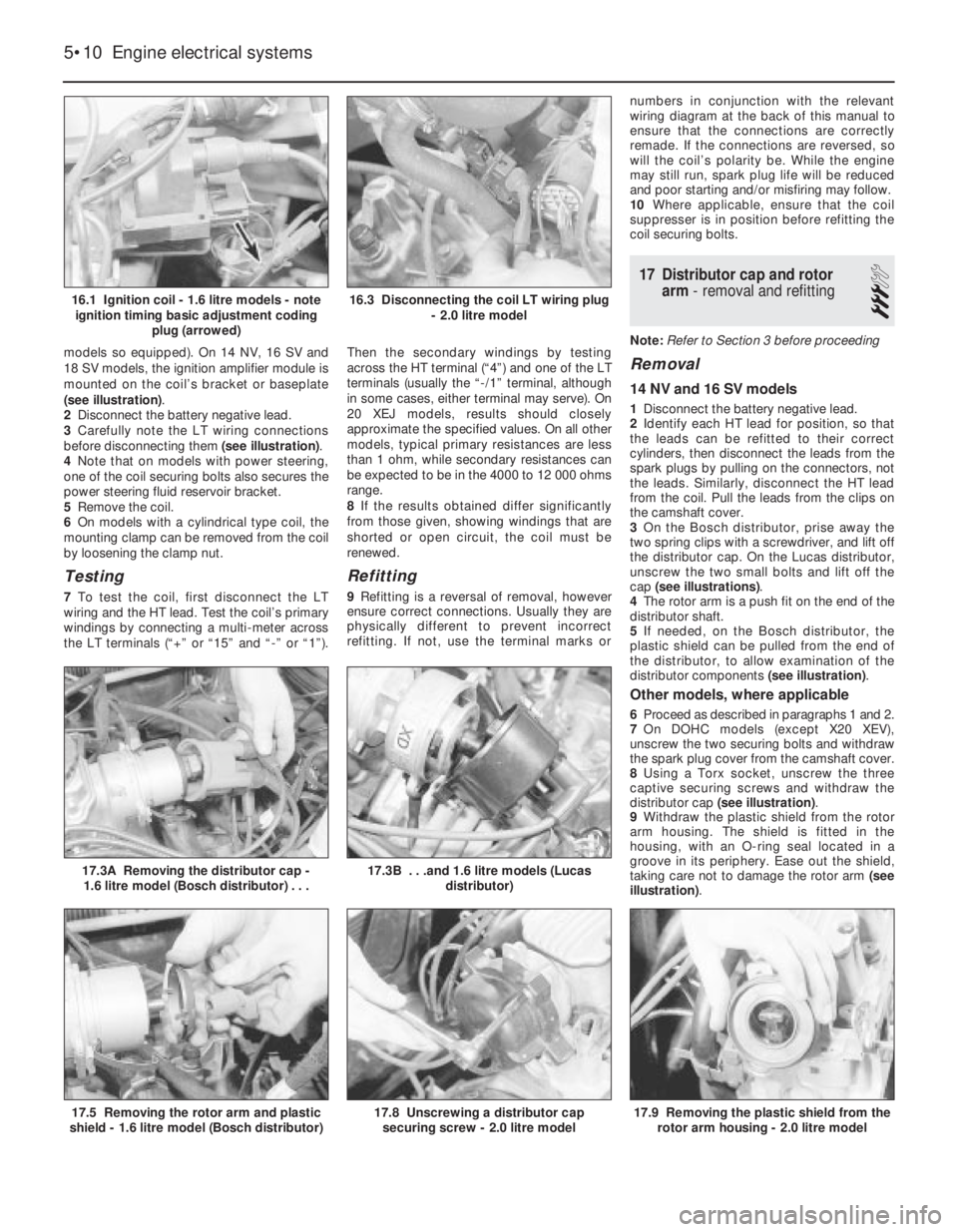
models so equipped). On 14 NV, 16 SV and
18 SV models, the ignition amplifier module is
mounted on the coil’s bracket or baseplate
(see illustration).
2Disconnect the battery negative lead.
3Carefully note the LT wiring connections
before disconnecting them (see illustration).
4Note that on models with power steering,
one of the coil securing bolts also secures the
power steering fluid reservoir bracket.
5Remove the coil.
6On models with a cylindrical type coil, the
mounting clamp can be removed from the coil
by loosening the clamp nut.
Testing
7To test the coil, first disconnect the LT
wiring and the HT lead. Test the coil’s primary
windings by connecting a multi-meter across
the LT terminals (“+” or “15” and “-” or “1”).Then the secondary windings by testing
across the HT terminal (“4”) and one of the LT
terminals (usually the “-/1” terminal, although
in some cases, either terminal may serve). On
20 XEJ models, results should closely
approximate the specified values. On all other
models, typical primary resistances are less
than 1 ohm, while secondary resistances can
be expected to be in the 4000 to 12 000 ohms
range.
8If the results obtained differ significantly
from those given, showing windings that are
shorted or open circuit, the coil must be
renewed.
Refitting
9Refitting is a reversal of removal, however
ensure correct connections. Usually they are
physically different to prevent incorrect
refitting. If not, use the terminal marks ornumbers in conjunction with the relevant
wiring diagram at the back of this manual to
ensure that the connections are correctly
remade. If the connections are reversed, so
will the coil’s polarity be. While the engine
may still run, spark plug life will be reduced
and poor starting and/or misfiring may follow.
10Where applicable, ensure that the coil
suppresser is in position before refitting the
coil securing bolts.
17Distributor cap and rotor
arm -removal and refitting
3
Note: Refer to Section 3 before proceeding
Removal
14 NV and 16 SV models
1Disconnect the battery negative lead.
2Identify each HT lead for position, so that
the leads can be refitted to their correct
cylinders, then disconnect the leads from the
spark plugs by pulling on the connectors, not
the leads. Similarly, disconnect the HT lead
from the coil. Pull the leads from the clips on
the camshaft cover.
3On the Bosch distributor, prise away the
two spring clips with a screwdriver, and lift off
the distributor cap. On the Lucas distributor,
unscrew the two small bolts and lift off the
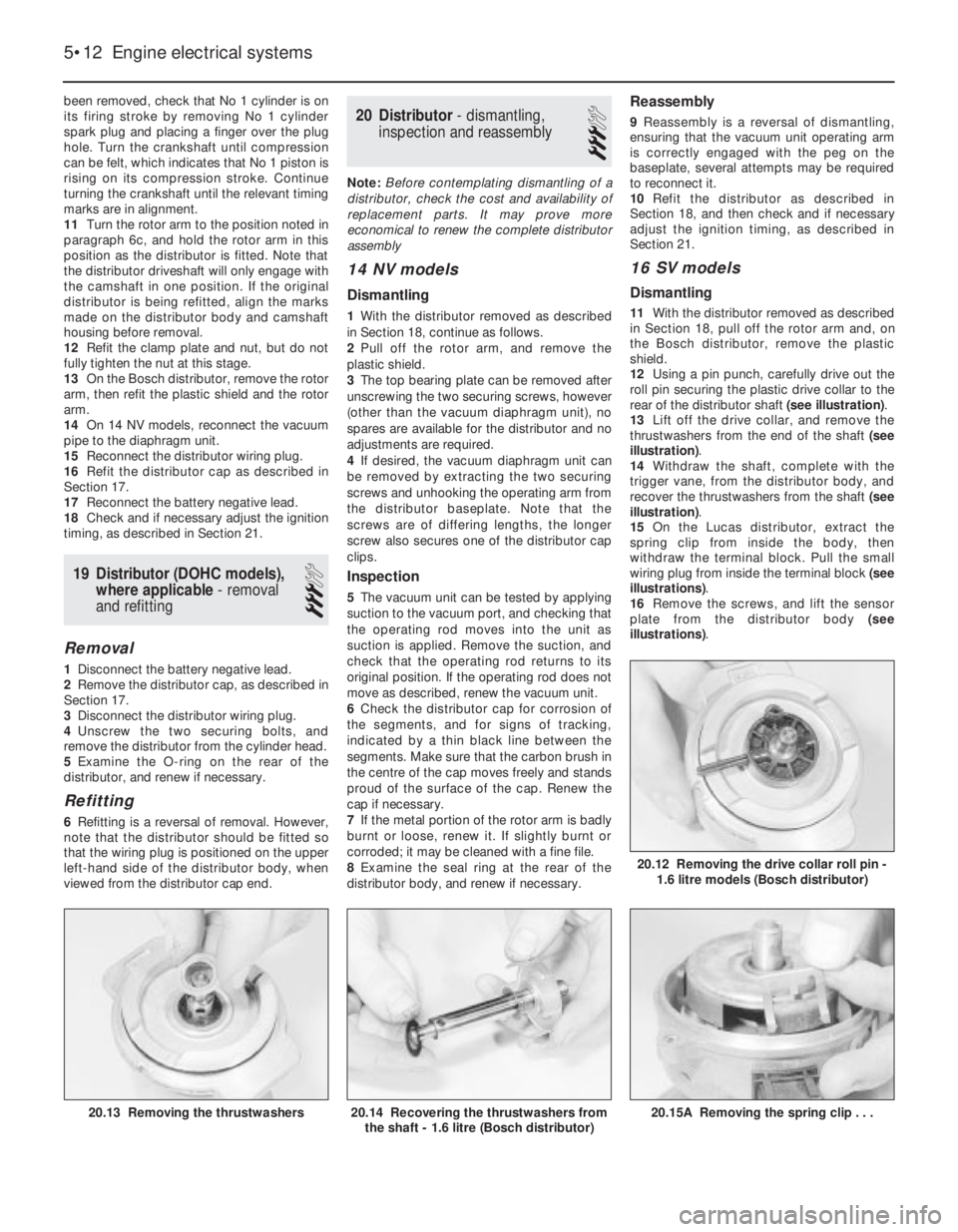
cap (see illustrations).
4The rotor arm is a push fit on the end of the
distributor shaft.
5If needed, on the Bosch distributor, the
plastic shield can be pulled from the end of
the distributor, to allow examination of the
distributor components (see illustration).
Other models, where applicable
6Proceed as described in paragraphs 1 and 2.
7On DOHC models (except X20 XEV),
unscrew the two securing bolts and withdraw
the spark plug cover from the camshaft cover.
8Using a Torx socket, unscrew the three
captive securing screws and withdraw the
distributor cap (see illustration).
9Withdraw the plastic shield from the rotor
arm housing. The shield is fitted in the
housing, with an O-ring seal located in a
groove in its periphery. Ease out the shield,
taking care not to damage the rotor arm (see
illustration).
5•10Engine electrical systems
16.1 Ignition coil - 1.6 litre models - note
ignition timing basic adjustment coding
plug (arrowed)
17.3A Removing the distributor cap -
1.6 litre model (Bosch distributor) . . .
17.9 Removing the plastic shield from the
rotor arm housing - 2.0 litre model17.8 Unscrewing a distributor cap
securing screw - 2.0 litre model17.5 Removing the rotor arm and plastic
shield - 1.6 litre model (Bosch distributor)
17.3B . . .and 1.6 litre models (Lucas
distributor)
16.3 Disconnecting the coil LT wiring plug
- 2.0 litre model
Page 98 of 525

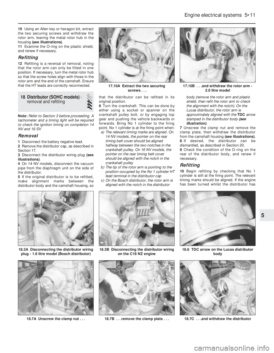
10Using an Allen key or hexagon bit, extract
the two securing screws and withdraw the
rotor arm, leaving the metal rotor hub in the
housing (see illustrations).
11Examine the O-ring on the plastic shield,
and renew if necessary.
Refitting
12Refitting is a reversal of removal, noting
that the rotor arm can only be fitted in one
position. If necessary, turn the metal rotor hub
so that the screw holes align with those in the
rotor arm and the end of the camshaft. Ensure
that the HT leads are correctly reconnected.
18Distributor (SOHC models) -
removal and refitting
3
Note: Refer to Section 3 before proceeding. A
tachometer and a timing light will be required
to check the ignition timing on completion 14
NV and 16 SV
Removal
1Disconnect the battery negative lead.
2Remove the distributor cap, as described in
Section 17.
3Disconnect the distributor wiring plug (see
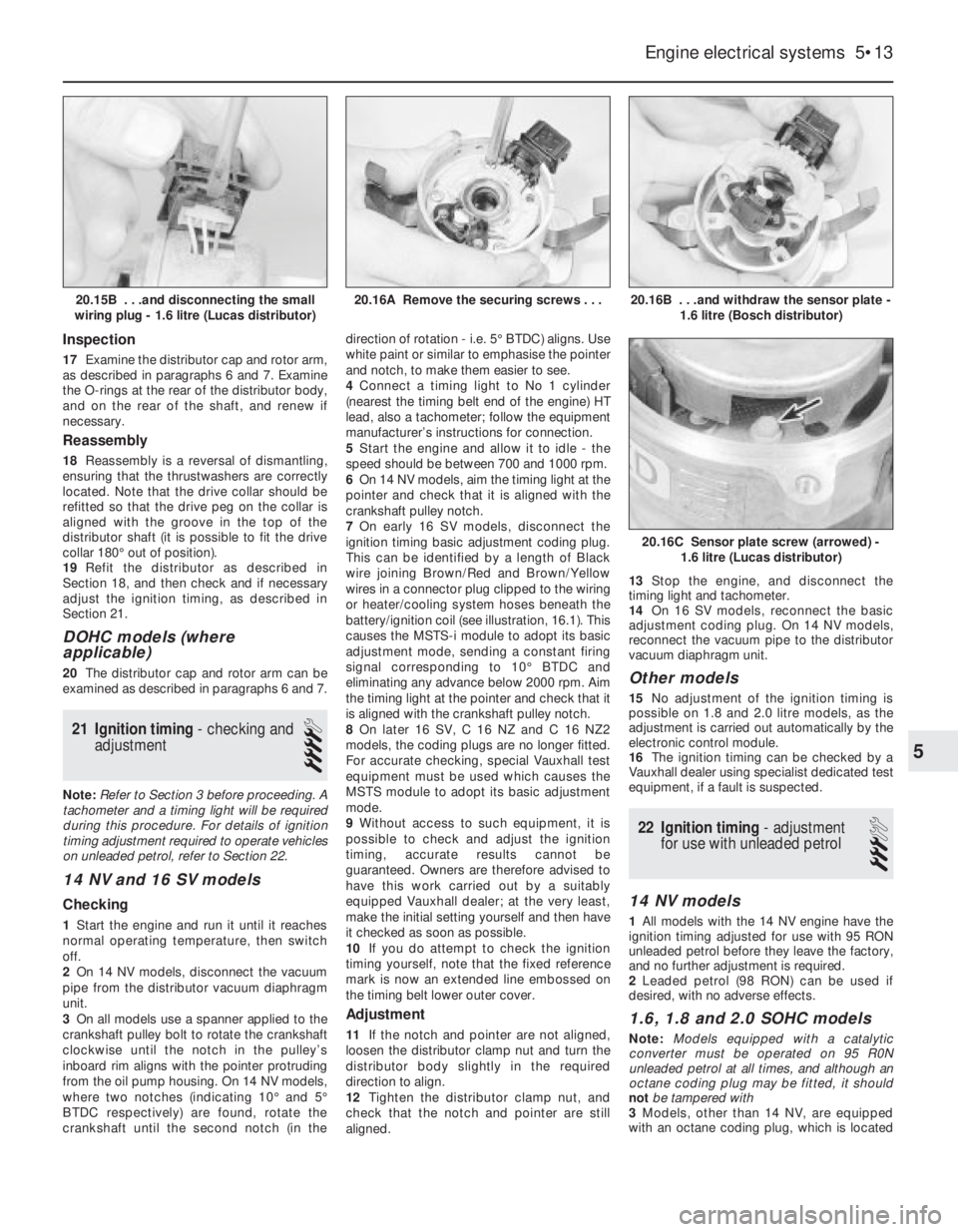
illustrations).
4On 14 NV models, disconnect the vacuum
pipe from the diaphragm unit on the side of
the distributor.
5If the original distributor is to be refitted,
make alignment marks between the
distributor body and the camshaft housing, sothat the distributor can be refitted in its
original position.
6Turn the crankshaft. This can be done by
either using a socket or spanner on the
crankshaft pulley bolt, or by engaging top
gear and pushing the vehicle backwards or
forwards. Bring No 1 cylinder to the firing
point. No 1 cylinder is at the firing point when:
a)The relevant timing marks are aligned. On
14 NV models, the pointer on the rear
timing belt cover should be aligned
halfway between the two notches in the
crankshaft pulley. On 16 NV models, the
pointer on the rear timing belt cover
should be aligned with the notch in the
crankshaft pulley
b)The tip of the rotor arm is pointing to the
position occupied by the No 1 cylinder HT
lead terminal in the distributor cap
c)On the Bosch distributor, the rotor arm is
aligned with the notch in the distributorbody (remove the rotor arm and plastic
shield, then refit the rotor arm to check
the alignment with the notch). On the
Lucas distributor, the rotor arm is
approximately aligned with the TDC arrow
stamped in the distributor body (see
illustration).
7Unscrew the clamp nut and remove the
clamp plate, then withdraw the distributor
from the camshaft housing (see illustrations).
8If desired, the distributor can be
dismantled, as described in Section 20.
9Check the condition of the O-ring on the
rear of the distributor body, and renew if
necessary.
Refitting
10Begin refitting by checking that No 1
cylinder is still at the firing point. The relevant
timing marks should be aligned. If the engine
has been turned whilst the distributor has
Engine electrical systems 5•11
18.6 TDC arrow on the Lucas distributor
body
18.7C . . .and withdraw the distributor18.7B . . .remove the clamp plate . . .18.7A Unscrew the clamp nut . . .
18.3B Disconnecting the distributor wiring
on the C16 NZ engine18.3A Disconnecting the distributor wiring
plug - 1.6 litre model (Bosch distributor)
17.10B . . .and withdraw the rotor arm -
2.0 litre model17.10A Extract the two securing
screws . . .
5
Page 99 of 525

been removed, check that No 1 cylinder is on
its firing stroke by removing No 1 cylinder
spark plug and placing a finger over the plug
hole. Turn the crankshaft until compression
can be felt, which indicates that No 1 piston is
rising on its compression stroke. Continue
turning the crankshaft until the relevant timing
marks are in alignment.
11Turn the rotor arm to the position noted in
paragraph 6c, and hold the rotor arm in this
position as the distributor is fitted. Note that
the distributor driveshaft will only engage with
the camshaft in one position. If the original
distributor is being refitted, align the marks
made on the distributor body and camshaft
housing before removal.
12Refit the clamp plate and nut, but do not
fully tighten the nut at this stage.
13On the Bosch distributor, remove the rotor
arm, then refit the plastic shield and the rotor
arm.
14On 14 NV models, reconnect the vacuum
pipe to the diaphragm unit.
15Reconnect the distributor wiring plug.
16Refit the distributor cap as described in
Section 17.
17Reconnect the battery negative lead.
18Check and if necessary adjust the ignition
timing, as described in Section 21.
19Distributor (DOHC models),
where applicable - removal
and refitting
3
Removal
1Disconnect the battery negative lead.
2Remove the distributor cap, as described in
Section 17.
3Disconnect the distributor wiring plug.
4Unscrew the two securing bolts, and
remove the distributor from the cylinder head.
5Examine the O-ring on the rear of the
distributor, and renew if necessary.
Refitting
6Refitting is a reversal of removal. However,
note that the distributor should be fitted so
that the wiring plug is positioned on the upper
left-hand side of the distributor body, when
viewed from the distributor cap end.
20Distributor - dismantling,
inspection and reassembly
3
Note: Before contemplating dismantling of a
distributor, check the cost and availability of
replacement parts. It may prove more
economical to renew the complete distributor
assembly
14 NV models
Dismantling
1With the distributor removed as described
in Section 18, continue as follows.
2Pull off the rotor arm, and remove the
plastic shield.
3The top bearing plate can be removed after
unscrewing the two securing screws, however
(other than the vacuum diaphragm unit), no
spares are available for the distributor and no
adjustments are required.
4If desired, the vacuum diaphragm unit can
be removed by extracting the two securing
screws and unhooking the operating arm from
the distributor baseplate. Note that the
screws are of differing lengths, the longer
screw also secures one of the distributor cap
clips.
Inspection
5The vacuum unit can be tested by applying
suction to the vacuum port, and checking that
the operating rod moves into the unit as
suction is applied. Remove the suction, and
check that the operating rod returns to its
original position. If the operating rod does not
move as described, renew the vacuum unit.
6Check the distributor cap for corrosion of
the segments, and for signs of tracking,
indicated by a thin black line between the
segments. Make sure that the carbon brush in
the centre of the cap moves freely and stands
proud of the surface of the cap. Renew the
cap if necessary.
7If the metal portion of the rotor arm is badly
burnt or loose, renew it. If slightly burnt or
corroded; it may be cleaned with a fine file.
8Examine the seal ring at the rear of the
distributor body, and renew if necessary.
Reassembly
9Reassembly is a reversal of dismantling,
ensuring that the vacuum unit operating arm
is correctly engaged with the peg on the
baseplate, several attempts may be required
to reconnect it.
10Refit the distributor as described in
Section 18, and then check and if necessary
adjust the ignition timing, as described in
Section 21.
16 SV models
Dismantling
11With the distributor removed as described
in Section 18, pull off the rotor arm and, on
the Bosch distributor, remove the plastic
shield.
12Using a pin punch, carefully drive out the
roll pin securing the plastic drive collar to the
rear of the distributor shaft (see illustration).
13Lift off the drive collar, and remove the
thrustwashers from the end of the shaft (see
illustration).
14Withdraw the shaft, complete with the
trigger vane, from the distributor body, and
recover the thrustwashers from the shaft (see
illustration).
15On the Lucas distributor, extract the
spring clip from inside the body, then
withdraw the terminal block. Pull the small
wiring plug from inside the terminal block (see
illustrations).
16Remove the screws, and lift the sensor
plate from the distributor body (see
illustrations).
5•12Engine electrical systems
20.15A Removing the spring clip . . .20.14 Recovering the thrustwashers from
the shaft - 1.6 litre (Bosch distributor)20.13 Removing the thrustwashers
20.12 Removing the drive collar roll pin -
1.6 litre models (Bosch distributor)
Page 100 of 525

Inspection
17Examine the distributor cap and rotor arm,
as described in paragraphs 6 and 7. Examine
the O-rings at the rear of the distributor body,
and on the rear of the shaft, and renew if
necessary.
Reassembly
18Reassembly is a reversal of dismantling,
ensuring that the thrustwashers are correctly
located. Note that the drive collar should be
refitted so that the drive peg on the collar is
aligned with the groove in the top of the
distributor shaft (it is possible to fit the drive
collar 180°out of position).
19Refit the distributor as described in
Section 18, and then check and if necessary
adjust the ignition timing, as described in
Section 21.
DOHC models (where
applicable)
20The distributor cap and rotor arm can be
examined as described in paragraphs 6 and 7.
21Ignition timing -checking and
adjustment
4
Note: Refer to Section 3 before proceeding. A
tachometer and a timing light will be required
during this procedure. For details of ignition
timing adjustment required to operate vehicles
on unleaded petrol, refer to Section 22.
14 NV and 16 SV models
Checking
1Start the engine and run it until it reaches
normal operating temperature, then switch
off.
2On 14 NV models, disconnect the vacuum
pipe from the distributor vacuum diaphragm
unit.
3On all models use a spanner applied to the
crankshaft pulley bolt to rotate the crankshaft
clockwise until the notch in the pulley’s
inboard rim aligns with the pointer protruding
from the oil pump housing. On 14 NV models,
where two notches (indicating 10°and 5°
BTDC respectively) are found, rotate the
crankshaft until the second notch (in thedirection of rotation -i.e. 5°BTDC) aligns. Use
white paint or similar to emphasise the pointer
and notch, to make them easier to see.
4Connect a timing light to No 1 cylinder
(nearest the timing belt end of the engine) HT
lead, also a tachometer; follow the equipment
manufacturer’s instructions for connection.
5Start the engine and allow it to idle -the
speed should be between 700 and 1000 rpm.
6On 14 NV models, aim the timing light at the
pointer and check that it is aligned with the
crankshaft pulley notch.
7On early 16 SV models, disconnect the
ignition timing basic adjustment coding plug.
This can be identified by a length of Black
wire joining Brown/Red and Brown/Yellow
wires in a connector plug clipped to the wiring
or heater/cooling system hoses beneath the
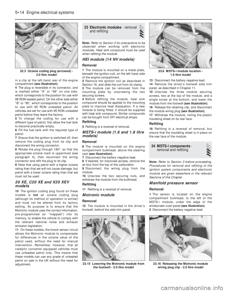
battery/ignition coil (see illustration, 16.1). This
causes the MSTS-i module to adopt its basic
adjustment mode, sending a constant firing
signal corresponding to 10°BTDC and
eliminating any advance below 2000 rpm. Aim
the timing light at the pointer and check that it
is aligned with the crankshaft pulley notch.
8On later 16 SV, C 16 NZ and C 16 NZ2
models, the coding plugs are no longer fitted.
For accurate checking, special Vauxhall test
equipment must be used which causes the
MSTS module to adopt its basic adjustment
mode.
9Without access to such equipment, it is
possible to check and adjust the ignition
timing, accurate results cannot be
guaranteed. Owners are therefore advised to
have this work carried out by a suitably
equipped Vauxhall dealer; at the very least,
make the initial setting yourself and then have
it checked as soon as possible.
10If you do attempt to check the ignition
timing yourself, note that the fixed reference
mark is now an extended line embossed on
the timing belt lower outer cover.
Adjustment
11If the notch and pointer are not aligned,
loosen the distributor clamp nut and turn the
distributor body slightly in the required
direction to align.
12Tighten the distributor clamp nut, and
check that the notch and pointer are still
aligned. 13Stop the engine, and disconnect the
timing light and tachometer.
14On 16 SV models, reconnect the basic
adjustment coding plug. On 14 NV models,
reconnect the vacuum pipe to the distributor
vacuum diaphragm unit.
Other models
15No adjustment of the ignition timing is
possible on 1.8 and 2.0 litre models, as the
adjustment is carried out automatically by the
electronic control module.
16The ignition timing can be checked by a
Vauxhall dealer using specialist dedicated test
equipment, if a fault is suspected.
22Ignition timing -adjustment
for use with unleaded petrol
3
14 NV models
1All models with the 14 NV engine have the
ignition timing adjusted for use with 95 RON
unleaded petrol before they leave the factory,
and no further adjustment is required.
2Leaded petrol (98 RON) can be used if
desired, with no adverse effects.
1.6, 1.8 and 2.0 SOHC models
Note: Models equipped with a catalytic
converter must be operated on 95 R0N
unleaded petrol at all times, and although an
octane coding plug may be fitted, it should
not be tampered with
3Models, other than 14 NV, are equipped
with an octane coding plug, which is located
Engine electrical systems 5•13
20.16B . . .and withdraw the sensor plate -
1.6 litre (Bosch distributor)
20.16C Sensor plate screw (arrowed) -
1.6 litre (Lucas distributor)
20.16A Remove the securing screws . . .20.15B . . .and disconnecting the small
wiring plug - 1.6 litre (Lucas distributor)
5
Page 101 of 525

in a clip at the left-hand rear of the engine
compartment (see illustration).
4The plug is reversible in its connector, and
is marked either “A” or “98” on one side,
which corresponds to the position for use with
98 RON leaded petrol. On the other side either
“B” or “95”, which corresponds to the position
to use with 95 RON unleaded petrol. All
vehicles are set for use with 95 RON unleaded
petrol before they leave the factory.
5To change the coding for use with a
different type of petrol, first allow the fuel tank
to become practically empty.
6Fill the fuel tank with the required type of
petrol.
7Ensure that the ignition is switched off, then
remove the coding plug from its clip and
disconnect the wiring connector.
8Rotate the plug through 180°, so that the
appropriate octane mark is uppermost (see
paragraph 4), then reconnect the wiring
connector and refit the plug to its clip.
9Note that using petrol with a higher octane
rating than that set will not cause damage, but
petrol with a lower octane rating than that set
must not be used.
20 XE, C20 XE and X20 XEV
models
10The ignition coding plug found on these
models is not an octane coding plug
(although its method of operation is similar)
and must not be altered from its factory
setting. Its purpose is to ensure that the
Motronic module uses the correct information,
pre-programmed (or “mapped”) into its
memory, to enable the vehicle to comply with
the relevant national noise and exhaust
emission legislation.
11On these models, the knock sensor circuit
allows the Motronic module to compensate
for differences in the octane value of the
petrol used, without the need for manual
intervention. Remember, however, that all
catalytic converter-equipped vehicles must
use unleaded petrol only. This means that
these models can use any grade of unleaded
petrol on sale in the UK without the need for
adjustment.
23Electronic modules - removal
and refitting
3
Note: Refer to Section 3 for precautions to be
observed when working with electronic
modules. Heat sink compound must be used
when refitting the module.
HEI module (14 NV models)
Removal
1The module is mounted on a metal plate,
beneath the ignition coil, on the left-hand side
of the engine compartment.
2Remove the ignition coil as described in
Section 16, and slide the coil from its clamp.
3The module can be removed from the
mounting plate by unscrewing the two
securing screws.
4Before refitting the module, heat sink
compound should be applied to the mounting
plate to improve heat dissipation. If a new
module is being fitted, it should be supplied
with heat sink compound. Similar compounds
can be bought from DIY electrical shops.
Refitting
5Refitting is a reversal of removal.
MSTS-i module (1.6 and 1.8 litre
models)
Removal
6The module is mounted on the engine
compartment bulkhead, above the steering
rack (see illustration).
7Disconnect the battery negative lead.
8If desired, for improved access, remove the
air box from the top of the carburettor.
9Disconnect the wiring plug from the
module.
10Unscrew the two securing nuts, and
withdraw the module from the bulkhead.
Refitting
11Refitting is a reversal of removal.
Motronic module
Removal
12The module is mounted in the driver’s
footwell, behind the side trim panel.13Disconnect the battery negative lead.
14Remove the driver’s footwell side trim
panel, as described in Chapter 11.
15Unscrew the three module securing
screws, two at the top of the module, and a
single screw at the bottom, and lower the
module from the footwell (see illustration).
16Release the retaining clip, and disconnect
the module wiring plug (see illustration).
17Withdraw the module, noting the plastic
insulating sheet on its rear face.
Refitting
18Refitting is a reversal of removal, but
ensure that the insulating sheet is in place on
the rear face of the module.
24MSTS-i components -
removal and refitting
3
Note: Refer to Section 3 before proceeding.
Procedures for removal and refitting of the
ignition system components and electronic
module are given elsewhere in the relevant
Sections of this Chapter
Manifold pressure sensor
Removal
1The sensor is located on the engine
compartment bulkhead, to the left of the
MSTS-i module, under the edge of the
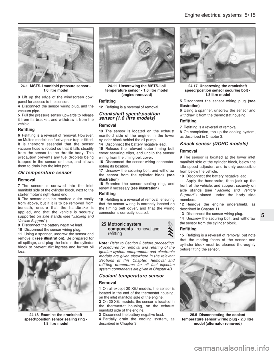
windscreen cowl panel (see illustration).
2Disconnect the battery negative lead.
5•14Engine electrical systems
22.3 Octane coding plug (arrowed) -
2.0 litre model
23.15 Lowering the Motronic module from
the footwell - 2.0 litre model23.16 Releasing the Motronic module
wiring plug clip - 2.0 litre model
23.6 MSTS-i module location -
1.6 litre model
Page 102 of 525

3Lift up the edge of the windscreen cowl
panel for access to the sensor.
4Disconnect the sensor wiring plug, and the
vacuum pipe.
5Pull the pressure sensor upwards to release
it from its bracket, and withdraw it from the
vehicle.
Refitting
6Refitting is a reversal of removal. However,
on Multec models no fuel vapour trap is fitted.
It is therefore essential that the sensor
vacuum hose is routed so that it falls steadily
from the sensor to the throttle body. This
precaution prevents any fuel droplets being
trapped in the sensor or hose, and allows
them to drain into the inlet port.
Oil temperature sensor
Removal
7The sensor is screwed into the inlet
manifold side of the cylinder block, next to the
starter motor’s right-hand end.
8The sensor can be reached quite easily
from above, but if it is to be removed from
beneath, ensure that the handbrake is
applied, and that the vehicle is securely
supported on axle stands (see “Jacking and
Vehicle Support”).
9Disconnect the battery negative lead.
10Disconnect the sensor wiring plug.
11Using a spanner, unscrew the sensor and
remove it (see illustration). Be prepared for
oil spillage, and plug the hole in the cylinder
block to prevent dirt ingress and further oil
loss.
Refitting
12Refitting is a reversal of removal.
Crankshaft speed/position
sensor (1.8 litre models)
Removal
13The sensor is located on the exhaust
manifold side of the engine, in the lower
cylinder block behind the oil pump.
14Disconnect the battery negative lead.
15Release the relevant outer timing belt
cover securing clips, and unclip the sensor
wiring from the timing belt cover.
16Disconnect the sensor wiring connector,
noting its location.
17Unscrew the securing bolt, and withdraw
the sensor from the cylinder block (see
illustration).
18Examine the sensor sealing ring, and
renew if necessary (see illustration).
Refitting
19Refitting is a reversal of removal, ensuring
that the sensor wiring is correctly located on
the timing belt cover, and that the wiring
connector is correctly located.
25Motronic system
components - removal and
refitting
3
Note: Refer to Section 3 before proceeding.
Procedures for removal and refitting of the
ignition system components and electronic
module are given elsewhere in the relevant
Sections of this Chapter. Removal and
refitting procedures for all fuel injection
system components are given in Chapter 4B
Coolant temperature sensor
Removal
1On all except 20 XEJ models, the sensor is
located in the end of the thermostat housing,
on the inlet manifold side of the engine.
2On 20 XEJ models, the sensor is located in
the thermostat housing, on the exhaust
manifold side of the engine.
3Disconnect the battery negative lead.
4Partially drain the cooling system, as
described in Chapter 3. 5Disconnect the sensor wiring plug (see
illustration).
6Using a spanner, unscrew the sensor and
withdraw it from the thermostat housing.
Refitting
7Refitting is a reversal of removal.
8On completion, top-up the cooling system,
as described in Chapter 3.
Knock sensor (DOHC models)
Removal
9The sensor is located at the lower inlet
manifold side of the cylinder block, below the
idle speed adjuster, and is only accessible
from below the vehicle.
10Disconnect the battery negative lead.
11Apply the handbrake, then jack up the
front of the vehicle, and support securely on
axle stands (see “Jacking and Vehicle
Support”) placed under the body side
members.
12Remove the engine undershield, as
described in Chapter 11.
13Disconnect the sensor wiring plug.
14Unscrew the securing bolt, and withdraw
the sensor from the cylinder block.
Refitting
15Refitting is a reversal of removal, but note
that the mating faces of the sensor and
cylinder block must be cleaned thoroughly
before fitting the sensor.
Engine electrical systems 5•15
24.17 Unscrewing the crankshaft
speed/position sensor securing bolt -
1.8 litre model
25.5 Disconnecting the coolant
temperature sensor wiring plug - 2.0 litre
model (alternator removed)24.18 Examine the crankshaft
speed/position sensor sealing ring -
1.8 litre model
24.11 Unscrewing the MSTS-i oil
temperature sensor - 1.6 litre model
(engine removed)24.1 MSTS-i manifold pressure sensor -
1.6 litre model
5
Page 103 of 525

26DIS module - removal and
refitting
3
Note: Refer to Section 3 before proceeding.
Removal
1Disconnect the battery negative lead.
2Disconnect the HT leads from the module
terminals noting their locations to ensure
correct refitting. Note that the HT lead cylinder
numbers are stamped on the module, next to
each terminal, and similar numbers appear on
each HT lead.
3Disconnect the module wiring plug.
4On X16 SZ engines, undo the three screws
and remove the module from the camshaft
housing. On C20 XE engines, undo the bolts
securing the DIS module mounting bracket tothe cylinder head and remove the module and
bracket. Note the installed position of DIS
module on its mounting bracket, undo the four
securing screws and separate the module
from the bracket.
Refitting
5Refitting is a reversal of removal.
27Camshaft phase sensor (C20
XE engine) -removal and
refitting
3
Note: Refer to Section 3 before proceeding.
Removal
1The camshaft phase sensor is mounted on
the end of the cylinder head in the position
normally occupied by the distributor.2Disconnect the battery negative lead.
3Disconnect the wiring plug then undo the
phase sensor securing bolts.
4Withdraw the phase sensor from the
cylinder head, then undo the bolt and remove
the phase sensor disc from the end of the
camshaft.
Refitting
5Refitting is a reversal of removal.
5•16Engine electrical systems
Page 104 of 525

11
Torque wrench settingNm lbf ft
Front seat rails to floor . . . . . . . . . . . . . . . . . . . . . . . . . . . . . . . . . . . . . . 20 15
Seat belt fixings . . . . . . . . . . . . . . . . . . . . . . . . . . . . . . . . . . . . . . . . . . . 35 26
1 General description
The bodyshell and floorpan are of pressed
steel, and form an integral part of the vehicle’s
structure, without the need for a separate
chassis.
Various areas are strengthened, to provide
for suspension, steering and engine mounting
points, and load distribution.
Extensive corrosion protection is applied to
all new vehicles. Various anti-corrosion
preparations are used, including galvanising
and PVC under-sealing. Protective wax is
injected into the box sections and other
hollow cavities.
Extensive use is made of plastic for
peripheral components, such as the radiator
grille, bumpers and wheel trims, and for much
of the interior trim.Interior fittings are to a high standard on all
models, and a wide range of optional
equipment is available throughout the range.
Except for the rear quarter windows, all
fixed glass is bonded in position, using a
special adhesive. Any work in this area should
be entrusted to a Vauxhall dealer or glass
replacement specialist.
2 Bodywork and underframe -
maintenance
1
The general condition of a vehicle’s
bodywork is the one thing that significantly
affects its value. Maintenance is easy but
needs to be regular. Neglect, particularly after
minor damage, can lead quickly to further
deterioration and costly repair bills. It is
important also to keep watch on those partsof the vehicle not immediately visible, for
instance the underside, inside all the wheel
arches and the lower part of the engine
compartment.
The basic maintenance routine for the
bodywork is washing preferably with a lot of
water, from a hose. This will remove all the
loose solids that may have stuck to the
vehicle. It is important to flush these off in
such a way as to prevent grit from scratching
the finish. The wheel arches and underframe
need washing in the same way to remove any
accumulated mud that will retain moisture and
tend to encourage rust. Oddly enough, the
best time to clean the underframe and wheel
arches is in wet weather when the mud is
thoroughly wet and soft. In very wet weather
the underframe is usually cleaned of large
accumulations automatically and this is a
good time for inspection.
Periodically, except on vehicles with a
Chapter 11
Bodywork and fittings
Bodywork and underframe - maintenance . . . . . . . . . . . . . . . . . . . . . .2
Bonnet - removal and refitting . . . . . . . . . . . . . . . . . . . . . . . . . . . . . . .6
Bonnet lock components - removal and refitting . . . . . . . . . . . . . . . . .7
Bonnet lock release cable - removal and refitting . . . . . . . . . . . . . . . .8
Boot lid (Saloon models) - removal and refitting . . . . . . . . . . . . . . . . .9
Boot lid lock (Saloon models) - removal and refitting . . . . . . . . . . . . .10
Boot lid lock cylinder (Saloon models) - removal and refitting . . . . . .11
Bumpers - removal and refitting . . . . . . . . . . . . . . . . . . . . . . . . . . . . .28
Centre console - removal and refitting . . . . . . . . . . . . . . . . . . . . . . . .38
Door - removal and refitting . . . . . . . . . . . . . . . . . . . . . . . . . . . . . . . .16
Door check arm - removal and refitting . . . . . . . . . . . . . . . . . . . . . . .22
Door exterior handle - removal and refitting . . . . . . . . . . . . . . . . . . . .19
Door inner trim panel - removal and refitting . . . . . . . . . . . . . . . . . . .17
Door interior handle - removal and refitting . . . . . . . . . . . . . . . . . . . .18
Door lock - removal and refitting . . . . . . . . . . . . . . . . . . . . . . . . . . . .21
Door lock barrel - removal and refitting . . . . . . . . . . . . . . . . . . . . . . .20
Door mirror - removal, overhaul and refitting . . . . . . . . . . . . . . . . . . .27
Door window - removal and refitting . . . . . . . . . . . . . . . . . . . . . . . . .25
Door window regulator - removal and refitting . . . . . . . . . . . . . . . . . .26
Engine undershield (DOHC models) - removal and refitting . . . . . . . .32
Facia panels - removal and refitting . . . . . . . . . . . . . . . . . . . . . . . . . .37
Fuel filler flap - removal and refitting . . . . . . . . . . . . . . . . . . . . . . . . .33General description . . . . . . . . . . . . . . . . . . . . . . . . . . . . . . . . . . . . . . .1
Headlining - removal and refitting . . . . . . . . . . . . . . . . . . . . . . . . . . .39
Interior trim panels - general . . . . . . . . . . . . . . . . . . . . . . . . . . . . . . . .35
Interior trim panels - removal and refitting . . . . . . . . . . . . . . . . . . . . .36
Major body damage - repair . . . . . . . . . . . . . . . . . . . . . . . . . . . . . . . . .5
Minor body damage - repair . . . . . . . . . . . . . . . . . . . . . . . . . . . . . . . . .4
Radiator grille panel - removal and refitting . . . . . . . . . . . . . . . . . . . .29
Rear quarter windows - removal and refitting . . . . . . . . . . . . . . . . . .24
Seat belts - removal and refitting . . . . . . . . . . . . . . . . . . . . . . . . . . . .41
Seat belt tensioners - general . . . . . . . . . . . . . . . . . . . . . . . . . . . . . . .42
Seats (without tensioners) - removal and refitting . . . . . . . . . . . . . . .40
Seats, front (with seat belt tensioners) - removal and refitting . . . . . .43
Sunroof - removal and refitting . . . . . . . . . . . . . . . . . . . . . . . . . . . . . .34
Tailgate (Hatchback models) - removal and refitting . . . . . . . . . . . . .12
Tailgate lock (Hatchback models) - removal and refitting . . . . . . . . .13
Tailgate lock cylinder (Hatchback models) - removal and refitting . .14
Tailgate strut (Hatchback models) - removal and refitting . . . . . . . . .15
Upholstery and carpets - maintenance . . . . . . . . . . . . . . . . . . . . . . . .3
Wheel arch liners - general . . . . . . . . . . . . . . . . . . . . . . . . . . . . . . . . .31
Windscreen and rear window - removal and refitting . . . . . . . . . . . . .23
Windscreen cowl panel - removal and refitting . . . . . . . . . . . . . . . . .30
11•1
Specifications Contents
Easy,suitable for
novice with little
experienceFairly easy,suitable
for beginner with
some experienceFairly difficult,
suitable for competent
DIY mechanic
Difficult,suitable for
experienced DIY
mechanicVery difficult,
suitable for expert DIY
or professional
Degrees of difficulty
54321