Page 129 of 525
Always keep the ignition and fuel systems
well maintained according to the
manufacturers schedule (see “Routine
maintenance” and the relevant Chapter).
In particular, ensure that the air cleaner")
b)Always keep the ignition and fuel systems
well maintained according to the
manufacturers schedule (see “Routine
maintenance” and the relevant Chapter).
In particular, ensure that the air cleaner
filter element, the fuel filter and the spark
plugs are renewed at the correct intervals.
If the inlet air/fuel mixture is allowed to
become too rich due to neglect, the
unburned surplus will enter and burn in
the catalytic converter, overheating the
element and eventually destroying the
converter.
c)If the engine develops a misfire, do not
drive the vehicle at all (or at least as little
as possible) until the fault is cured. The
misfire will allow unburned fuel to enter
the converter, which will result in its
overheating, as noted above.
d)The engine control indicator (the outline
of an engine with a lightning symbol
superimposed), will light when the ignition
is switched on and the engine is started,
then it will go out. While it may light briefly
while the engine is running, it should go
out again immediately and stays unlit. If it
lights and stays on while the engine is
running, seek the advice of a Vauxhall
dealer as soon as possible. A fault has
occurred in the fuel injection/ignition
system that, apart from increasing fuel
consumption and impairing the engine’s
performance, may damage the catalytic
converter.
e)DO NOT push or tow-start the vehicle.
This will soak the catalytic converter in
unburned fuel causing it to overheat when
the engine does start see (b) above.
f)DO NOT switch off the ignition at high
engine speeds. If the ignition is switched
off at anything above idle speed,
unburned fuel will enter the (very hot)
catalytic converter, with the possible risk
of its igniting on the element and
damaging the converter.
g)DO NOT use fuel or engine oil additives.
These may contain substances harmful to
the catalytic converter.
h)DO NOT continue to use the vehicle if the
engine burns oil to the extent of leaving a
visible trail of blue smoke. The unburned
carbon deposits will clog the converter
passages and reduce its efficiency; in
severe cases the element will overheat.
i)Remember that the catalytic converter
operates at very high temperatures hence
the heat shields on the vehicle’s under-
body and the casing will become hot
enough to ignite combustible materials
that brush against it. DO NOT, therefore,
park the vehicle in dry undergrowth, over
long grass or over piles of dead leaves.
j)Remember that the catalytic converter is
FRAGlLE. Do not strike it with tools during
servicing work. Take great care when
working on the exhaust system. Ensure
that the converter is well clear of any
jacks or other lifting gear used to raise thevehicle. Do not drive the vehicle over
rough ground, road humps, etc., in such a
way as to ground the exhaust system.
k)In some cases, particularly when the
vehicle is new and/or is used for
stop/start driving, a sulphurous smell (like
that of rotten eggs) may be noticed from
the exhaust. This is common to many
catalytic converter-equipped vehicles and
seems to be due to the small amount of
sulphur found in some petrol’s reacting
with hydrogen in the exhaust to produce
hydrogen sulphide (CS) gas. While this
gas is toxic, it is not produced in sufficient
amounts to be a problem. Once the
vehicle has covered a few thousand miles
the problem should disappear. In the
meanwhile a change of driving style or of
the brand of petrol may effect a solution.
l)The catalytic converter, used on a
well-maintained and well-driven vehicle,
should last for between 50 000 and 100
000 miles. From this point on, careful
checks should be made at all specified
service intervals of the CO level to ensure
that the converter is still operating
efficiently. If the converter is no longer
effective it must be renewed.
11Carbon canister - removal
and refitting
3
Removal
1Apply the handbrake, then jack up the front
of the vehicle, and support securely on axle
stands placed under the body side members
(see “Jacking and Vehicle Support”).
2Remove the front right hand wheel and
wheel arch liner.
3Note the hose and pipe connections to the
canister, or label them, to ensure that they are
reconnected to their original unions, then
disconnect them (see illustration). Unscrew
the two nuts securing the canister mounting
bracket to the vehicle body.
Refitting
4Refitting is a reversal of removal, however
ensure correct fitment of hose and pipes.
12Oxygen sensor (catalytic
converter models) - removal
and refitting
3
Note: This sensor is also known as a Lambda
sensor.
Removal
1Disconnect the battery negative lead.
2Disconnect the oxygen sensor wiring plug,
which is located behind the coolant expansion
tank.
3Apply the handbrake, then jack up the front
of the vehicle, and support securely on axle
stands placed under the body side members.
4On DOHC models, remove the engine
undershield, as described in Chapter 11.
5On models fitted with Multec injection
system, the sensor is screwed into the
exhaust manifold. Trace the wiring from the
sensor itself to the connector (either clipped
to the radiator cooling fan shroud or behind
the coolant expansion tank). Release it from
any clips or ties; disconnect the wiring before
unscrewing the sensor.
6On other models, unscrew the oxygen
sensor from the front section of the exhaust
system (see illustration). It is advisable to
wear gloves, as the exhaust system will be
extremely hot.
7Withdraw the oxygen sensor and its wiring,
taking care not to burn the wiring on the
exhaust system. If the sensor is to be re-used,
take care that the sealing ring is not lost, and
that the sensor is not dropped.
Refitting
8If a new sensor is being fitted, it will be
supplied with the threads coated in a special
grease to prevent it seizing in the exhaust
system.
9If the original sensor is being refitted,
ensure that the screw thread is clean. Coat
the thread with a lithium based copper grease
(i.e. Vauxhall Part No. 90295397).
10Refitting is a reversal of removal. Check
the exhaust system for leakage when the
engine is re-started.
4C•4Fuel and exhaust systems - exhaust and emissions
12.6 Oxygen sensor location in front
section of exhaust system - DOHC models
11.3 Charcoal canister
A Vent to atmosphere
B Vapour feed hose from filler pipe
C Vapour exhaust hose to inlet tract
D Control valve vacuum pipe from
throttle body
Page 130 of 525

13Exhaust manifold - removal
and refitting
3
Note:New manifold-to-cylinder head, and
manifold-to-downpipe, gaskets must be used
on refitting. Exhaust manifolds on DOHC
models are of tubular design, which form part
of the front section of the exhaust.
Removal
1Disconnect the battery negative lead.
2Disconnect the HT leads from the spark
plugs, if necessary labelling them to ensure
refitting to the correct cylinders.
3Loosen the clamp screw and disconnect
the air cleaner hot air tube from the shroud on
the manifold, if fitted. Remove the securing
screws and withdraw the hot air shroud from
the manifold.
4Working under the manifold, unscrew and
remove the four bolts securing the exhaust
downpipe to the manifold.
5If fitted, disconnect the oxygen sensor
wiring
6Separate the downpipe from the manifold,
and support with wire or string. Do not allow
the front section of the exhaust system to hang
under its own weight. Recover the gasket.
7Unscrew the securing nuts, and withdraw
the manifold from the cylinder head (see
illustration). Recover the gasket.
8It is possible that some of the manifold
studs may be unscrewed from the cylinder
head when the manifold securing nuts are
unscrewed. In this event, the studs should be
screwed back into the cylinder head once the
manifold has been removed, using two
manifold nuts locked together.
Refitting
9Refit the manifold using a new gasket, and
tighten the securing nuts to the specified
torque.
10Reconnect the exhaust downpipe to the
manifold, using a new gasket and tighten the
securing bolts to the specified torque.
11Further refitting is a reversal of removal.
14Exhaust system - checking,
removal and refitting
2
Note: All relevant gaskets and/or sealing rings
should be renewed on refitting
Checking
1Periodically, the exhaust system should be
checked for signs of leaks or damage. Also
inspect the exhaust system rubber
mountings, and renew if necessary.
2Small holes or cracks can be repaired using
proprietary exhaust repair products, but
where more serious corrosion or damage is
evident, renewal will be necessary.
Removal
3The original factory-fitted exhaust system
consists of four separate sections, all of which
can be renewed individually.
4On models fitted with a catalytic converter,
an oxygen sensor is fitted to the front section
of the exhaust. The catalytic converter is fitted
in place of the front expansion box in the
conventional exhaust system. The
manufacturers do not specify any renewal
intervals for the catalytic converter.
5Before renewing an individual section of the
exhaust system, it is wise to inspect the
remaining sections. If corrosion or damage is
evident on more than one section of the
system, it may prove more economical to
renew the entire system.
6Individual sections of the exhaust system
can be removed as follows.
Front section - SOHC models
7On models with a catalytic converter,
disconnect the battery negative lead, and
disconnect the oxygen sensor wiring plug,
which is located behind the coolant expansion
tank.
8Raise the vehicle, and support securely on
axle stands placed under the body side
members (see “Jacking and Vehicle
Support”).
9Unscrew the two securing bolts, and
disconnect the exhaust front section from the
front expansion box or catalytic converter (as
applicable) at the flexible joint. Recover the
sealing ring and the springs (see illustration).10Unbolt the exhaust front section from the
bracket on the cylinder block (see
illustration).
11Unscrew and remove the four bolts
securing the downpipe to the exhaust
manifold, and withdraw the exhaust front
section (see illustration). Recover the
downpipe-to-manifold gasket.
Refitting
12Refitting is a reversal of removal, but use a
new gasket when reconnecting the downpipe
to the manifold, and a new sealing ring when
connecting the flexible joint. Tighten all fixings
to the specified torque.
Front section - DOHC models
Removal
13Proceed as described in paragraphs 7
and 8.
14Remove the engine undershield, as
described in Chapter 11.
15Proceed as described in paragraphs 9
and 10.
16Working in the engine compartment,
remove the bolts securing the exhaust
manifold heat shield to the cylinder head.
17Unscrew the two lower exhaust manifold
securing nuts that also secure the heat shield
brackets, and withdraw the heat shield (see
illustration).
18Unscrew the remaining manifold securing
nuts, then withdraw the manifold/exhaust
front section from the vehicle. Recover the
manifold gasket.
Fuel and exhaust systems - exhaust and emissions 4C•5
14.10 Exhaust front section support
bracket - SOHC models
14.11 Unscrewing a downpipe-to-exhaust
manifold bolt - SOHC models
14.9 Exhaust front section flexible joint -
SOHC models13.7 Unscrewing an exhaust manifold
securing nut - SOHC models
4C
Page 131 of 525

19It is possible that some of the manifold
studs may be unscrewed from the cylinder
head when the manifold securing nuts are
unscrewed. In this event, the studs should be
screwed back into the cylinder head once the
manifold has been removed, using two
manifold nuts locked together.
Refitting
20Refitting is a reversal of removal, but use a
new manifold gasket, and use a new sealing
ring when reconnecting the flexible joint.
Tighten all fixings to the specified torque.
Front expansion box/catalytic
converter
Removal
21Proceed as described in paragraphs 8
and 9.
22Unscrew the three securing nuts and
bolts, and disconnect the expansion
box/catalytic converter from the exhaust
centre section flanged joint. Recover the
gasket.
23Withdraw the expansion box/catalytic
converter from the vehicle.
Refitting
24Refitting is a reversal of removal, but use a
new sealing ring when reconnecting the
flexible joint, and a new gasket when
reconnecting the flanged joint. Tighten all
fixings to the specified torque.
Centre section
Removal
25Raise the vehicle, and support securely on
axle stands placed under the body side
members.
26Unscrew the clamp bolt, and disconnect
the exhaust centre section from the rear
section (see illustration). If necessary, tap
around the joint with a hammer to break the
seal, and gently prise the two sections apart.
Note that the end of the centre section fits
inside the rear section, to form a sleeve joint.
27Proceed as described in paragraph 22.
28Release the exhaust centre section from
its rubber mountings on the underbody, and
withdraw it from the vehicle (see illustration).
Refitting
29Refitting is a reversal of removal, but use a
new gasket when reconnecting the flanged
joint, and lubricate the pipes with exhaust
assembly paste when connecting the centre
section to the rear section. Tighten all fixings
to the specified torque.
Rear section
Removal
30Proceed as described in paragraphs 25
and 26.
31Release the exhaust rear section from its
rubber mountings on the underbody, and
withdraw it from the vehicle.
Refitting
32Refitting is a reversal of removal, but
lubricate the pipes with exhaust assembly
paste when connecting the rear section to the
centre section. Tighten the clamp bolt to the
specified torque.
4C•6Fuel and exhaust systems - exhaust and emissions
14.28 Exhaust centre section forward
rubber mountings - DOHC models14.26 Exhaust centre section-to-rear
section clamp (arrowed) - SOHC model14.17 Exhaust manifold nut (arrowed)
securing exhaust heat shield - DOHC
models
Page 132 of 525

9
System type
Models without ABS:
1.4, 1.6 and 1.8 litre models . . . . . . . . . . . . . . . . . . . . . . . . . . . . . . . . Front discs and rear drums, with vacuum servo assistance, dual
hydraulic circuit split diagonally, pressure-proportioning valves in rear
hydraulic circuit. Cable-operated handbrake on rear wheels
2.0 litre models . . . . . . . . . . . . . . . . . . . . . . . . . . . . . . . . . . . . . . . . . . Front and rear discs, with vacuum servo assistance, dual hydraulic
circuit split diagonally, pressure-proportioning valves in rear hydraulic
circuit. Cable-operated handbrake on rear wheels
All models with Anti-lock Braking System (ABS) . . . . . . . . . . . . . . . . . . Front and rear discs, with vacuum servo assistance, operated via
hydraulic modulator, dual hydraulic circuit split front/rear, pressure-
proportioning valves in rear hydraulic circuit. Cable-operated
handbrake on rear wheels
Front discs
Type:
1.4, 1.6 and 1.8 litre models . . . . . . . . . . . . . . . . . . . . . . . . . . . . . . . . Solid or ventilated (as from 10/91)
2.0 litre models . . . . . . . . . . . . . . . . . . . . . . . . . . . . . . . . . . . . . . . . . . Ventilated
Diameter:
1.4, 1.6 and early 1.8 litre models . . . . . . . . . . . . . . . . . . . . . . . . . . . . 236 mm
Late (as from 10/91) 1.8 and 2.0 litre models . . . . . . . . . . . . . . . . . . . 256 mm
Maximum disc run-out (all models) . . . . . . . . . . . . . . . . . . . . . . . . . . . . 0.1 mm
Minimum pad friction material thickness (including backing plate):
All models . . . . . . . . . . . . . . . . . . . . . . . . . . . . . . . . . . . . . . . . . . . . . . 7.0 mm
Minimum disc thickness after machining: *
1.4, 1.6 and 1.8 litre models (with solid discs) . . . . . . . . . . . . . . . . . . 10.7 mm
1.4, 1.6 and 1.8 litre models (with vented discs) . . . . . . . . . . . . . . . . 18.0 mm
2.0 litre models . . . . . . . . . . . . . . . . . . . . . . . . . . . . . . . . . . . . . . . . . . 22.0 mm
* When this dimension is reached, only one further new set of brake pads is permissible, then renew the discs
Chapter 9
Braking system
ABS electronic control module - removal and refitting . . . . . . . . . . .22
ABS hydraulic modulator - removal and refitting . . . . . . . . . . . . . . . .20
ABS relays (ABS-2E systems only) - removal and refitting . . . . . . . .23
ABS wheel sensors - removal and refitting . . . . . . . . . . . . . . . . . . . .21
Anti-lock braking system (ABS) - general . . . . . . . . . . . . . . . . . . . . . . .2
Brake disc - inspection, removal and refitting . . . . . . . . . . . . . . . . . .10
Brake drum - removal, inspection and refitting . . . . . . . . . . . . . . . . .11
Brake fluid pipes and hoses - general, removal and refitting . . . . . . .25
Brake pedal - removal and refitting . . . . . . . . . . . . . . . . . . . . . . . . . .29
Front brake disc shield - removal and refitting . . . . . . . . . . . . . . . . . .14
Front disc caliper - removal, overhaul and refitting . . . . . . . . . . . . . . .8
Front disc pads - inspection, removal and refitting . . . . . . . . . . . . . . .4
General description . . . . . . . . . . . . . . . . . . . . . . . . . . . . . . . . . . . . . . .1
Handbrake - adjustment . . . . . . . . . . . . . . . . . . . . . . . . . . . . . . . . . . .26
Handbrake cable - removal and refitting . . . . . . . . . . . . . . . . . . . . . .27Handbrake lever - removal and refitting . . . . . . . . . . . . . . . . . . . . . . .28
Handbrake shoes (rear disc brakes) - inspection, removal and
refitting . . . . . . . . . . . . . . . . . . . . . . . . . . . . . . . . . . . . . . . . . . . . . . .7
Hydraulic system - bleeding . . . . . . . . . . . . . . . . . . . . . . . . . . . . . . . . .3
Master cylinder - removal and refitting . . . . . . . . . . . . . . . . . . . . . . . .15
Master cylinder (ABS) - general . . . . . . . . . . . . . . . . . . . . . . . . . . . . .17
Master cylinder (non-ABS) - overhaul . . . . . . . . . . . . . . . . . . . . . . . . .16
Rear brake backplate - removal and refitting . . . . . . . . . . . . . . . . . . .13
Rear brake pressure-proportioning valves - removal and refitting . . .24
Rear brake shoes (drum brakes) - inspection, removal and refitting . .6
Rear disc caliper - removal, overhaul and refitting . . . . . . . . . . . . . . . .9
Rear disc pads - inspection, removal and refitting . . . . . . . . . . . . . . . .5
Rear wheel cylinder (drum brakes) - removal, overhaul and refitting .12
Vacuum servo - description and testing . . . . . . . . . . . . . . . . . . . . . . .18
Vacuum servo - removal and refitting . . . . . . . . . . . . . . . . . . . . . . . . .19
9•1
Specifications Contents
Easy,suitable for
novice with little
experienceFairly easy,suitable
for beginner with
some experienceFairly difficult,
suitable for competent
DIY mechanic
Difficult,suitable for
experienced DIY
mechanicVery difficult,
suitable for expert DIY
or professional
Degrees of difficulty
54321
Page 133 of 525
 . . . . . . . . . . . . . . . . . . . . . . . . . . . . . . . . . . . . . . . . . . .Solid
Diameter (all models) . . . . . . . . . . . . . . . . . . . . . . . . . . . . .")
Rear discs
Type (all models) . . . . . . . . . . . . . . . . . . . . . . . . . . . . . . . . . . . . . . . . . . .Solid
Diameter (all models) . . . . . . . . . . . . . . . . . . . . . . . . . . . . . . . . . . . . . . .260 mm
Maximum disc run-out (all models) . . . . . . . . . . . . . . . . . . . . . . . . . . . .0.1 mm
Minimum pad friction material thickness (including backing plate):
All models . . . . . . . . . . . . . . . . . . . . . . . . . . . . . . . . . . . . . . . . . . . . . .7.0 mm
Minimum disc thickness after machining (all models) * . . . . . . . . . . . . .8.0 mm
* When this dimension is reached, only one further new set of disc pads is permissible, then renew the discs
Minimum handbrake shoe friction material thickness (lining only)
All models . . . . . . . . . . . . . . . . . . . . . . . . . . . . . . . . . . . . . . . . . . . . . .1.0 mm
Rear drums
Internal diameter (all models) . . . . . . . . . . . . . . . . . . . . . . . . . . . . . . . . .200 mm
Minimum shoe friction material thickness (all models) . . . . . . . . . . . . . .0.5 mm above rivet heads
Brake fluid type/specification:
All models . . . . . . . . . . . . . . . . . . . . . . . . . . . . . . . . . . . . . . . . . . . . . .See Lubricants and fluidsin “Weekly checks”
Torque wrench settingsNmlbf ft
ABS hydraulic modulator mounting . . . . . . . . . . . . . . . . . . . . . . . . . . . .86
ABS wheel sensor mounting . . . . . . . . . . . . . . . . . . . . . . . . . . . . . . . . .86
ABS control unit . . . . . . . . . . . . . . . . . . . . . . . . . . . . . . . . . . . . . . . . . . .1.51
Brake fluid line unions . . . . . . . . . . . . . . . . . . . . . . . . . . . . . . . . . . . . . .1612
Caliper and wheel cylinder bleed screws . . . . . . . . . . . . . . . . . . . . . . . .97
Front brake disc securing screw . . . . . . . . . . . . . . . . . . . . . . . . . . . . . .43
Front brake fluid hose to caliper union . . . . . . . . . . . . . . . . . . . . . . . . . .4030
Front caliper bracket to hub carrier . . . . . . . . . . . . . . . . . . . . . . . . . . . .9570
Front caliper guide . . . . . . . . . . . . . . . . . . . . . . . . . . . . . . . . . . . . . . . . .3022
Front caliper mounting (solid disc models) . . . . . . . . . . . . . . . . . . . . . . .9570
Front caliper to mounting bracket (vented disc models) . . . . . . . . . . . .3022
Handbrake lever securing . . . . . . . . . . . . . . . . . . . . . . . . . . . . . . . . . . . .2015
Master cylinder mounting . . . . . . . . . . . . . . . . . . . . . . . . . . . . . . . . . . . .2216
Master cylinder stop screw (ATE type) . . . . . . . . . . . . . . . . . . . . . . . . . .64
Pressure proportioning valve to master cylinder:
ATE type . . . . . . . . . . . . . . . . . . . . . . . . . . . . . . . . . . . . . . . . . . . . . . .129
GMF type . . . . . . . . . . . . . . . . . . . . . . . . . . . . . . . . . . . . . . . . . . . . . .4030
Rear brake backplate/stub axle spring:
Stage 1 . . . . . . . . . . . . . . . . . . . . . . . . . . . . . . . . . . . . . . . . . . . . . . . .5037
Stage 2 . . . . . . . . . . . . . . . . . . . . . . . . . . . . . . . . . . . . . . . . . . . . . . . .Angle-tighten a further 30º
Stage 3 . . . . . . . . . . . . . . . . . . . . . . . . . . . . . . . . . . . . . . . . . . . . . . . .Angle-tighten a further 15º
Rear brake disc securing screw . . . . . . . . . . . . . . . . . . . . . . . . . . . . . . .86
Rear caliper mounting . . . . . . . . . . . . . . . . . . . . . . . . . . . . . . . . . . . . . .8059
Rear drum securing screw . . . . . . . . . . . . . . . . . . . . . . . . . . . . . . . . . . .43
Rear wheel cylinder mounting . . . . . . . . . . . . . . . . . . . . . . . . . . . . . . . .97
Vacuum servo support bracket to bulkhead . . . . . . . . . . . . . . . . . . . . .2216
Vacuum servo to support bracket . . . . . . . . . . . . . . . . . . . . . . . . . . . . .2015
1General description
The foot brake operates on all four wheels.
Solid or ventilated disc brakes are fitted at the
front, and self-adjusting drum or solid disc
brakes are fitted at the rear, depending on
model. Actuation is hydraulic, with vacuum
servo assistance. The handbrake is cable-
operated, and acts on the rear wheels only.
The hydraulic system is split into two
circuits. On non-ABS models, the system is
split diagonally, and on ABS models, the
system is split front and rear. If there is a
hydraulic fluid leak in one circuit, the
remaining circuit will still function, so that
some braking capability remains.
The hydraulic fluid supply to the rear brakes
is regulated so that the front brakes alwayslock first under heavy braking. The fluid
pressure to the rear brakes is controlled by
two valves, one for each brake, which are
either screwed into the master cylinder or
mounted on the rear underbody of the vehicle,
depending on model.
The brake servo is of the direct-acting type,
fitted between the pedal and the master
cylinder. The servo is powered by vacuum
developed in the inlet manifold. Should the
servo fail, the brakes will still operate, but
increased pedal pressure will be required.
2Anti-lock braking system
(ABS) - general
1ABS is available as an option for all models.
When the ignition is switched on, an ‘ABS’
symbol illuminates in the instrument panel for
a short time. 2The system comprises an electronic control
unit, roadwheel sensors, hydraulic modulator,
and the necessary valves and relays. Disc
brakes are fitted to all four wheels. The
purpose of the system is to stop wheel(s)
locking during heavy brake applications. This
is achieved by automatic release of the brake
on the locked wheel, followed by re-
application of the brake. This procedure is
carried out several times a second by the
hydraulic modulator.
3The modulator is controlled by the
electronic control unit, which itself receives
signals from the wheel sensors, which monitor
the locked or unlocked state of the wheels.
The two front brakes are modulated
separately, but the two rear brakes are
modulated together.
4The ABS unit is fitted between the brake
master cylinder and the brakes, the vacuum
servo and master cylinder being of similar
type for both non-ABS and ABS models.
9•2Braking system
Page 134 of 525

5If the ‘ABS’ symbol, in the instrument panel
stays lit after approximately 4 seconds, or if it
comes on sporadically or stays on whilst
driving, there is a fault in the system. Should
this occur, it is recommended that a complete
test is carried out by a Vauxhall dealer, who
will have the necessary specialist diagnostic
equipment. Due to the special equipment
required, it is not practical for the DIY
mechanic to carry out the test procedure.
6To prevent possible damage to the
electronic control unit, always disconnect the
control unit wiring plug before carrying out
electrical welding work.
7It is recommended that the control unit is
removed if the vehicle is being subjected to
high temperatures, like for instance, during
certain paint-drying processes.
8If using steam cleaning equipment, do not
aim the water/steam jet directly at the control
unit.
9Do not disconnect the control unit wiring
plug with the ignition switched on.
10Do not use a battery booster to start the
engine.
11After working on the ABS components,
ensure that all wiring plugs are correctly
reconnected, and have the complete system
tested by a Vauxhall dealer, at the earliest
opportunity.
12All models up to 1991 that were fitted with
ABS, used the ABS-2E system. From 1992
onwards an ABS-2EH system was fitted,
which can be identified by the location of the
electronic control module, which is bolted to
the hydraulic modulator.
13The main differences between the two
systems are in the electrical components and
circuits, the most obvious of these being
omission of the surge arrester relay on the
2EH system.
3Hydraulic system - bleeding
2
General
1If any of the hydraulic components in the
braking system have been removed or
disconnected, or if the fluid level in the
reservoir has been allowed to fall appreciably,
it is certain that air will have entered into the
system. The removal of all this air from the
hydraulic system is essential if the brakes are
to function correctly, and the process of
removing it is known as bleeding.
2Where an operation has only affected one
circuit of the hydraulic system (the system issplit diagonally on non-ABS models, and front
and rear on ABS models), then it will only be
necessary to bleed the relevant circuit. If the
master cylinder has been disconnected and
reconnected, or the fluid level has been
allowed to fall appreciably, then the complete
system must be bled.
3One of three methods can be used to bleed
the system, although Vauxhall recommend
the use of a pressure bleeding kit.
Bleeding - two-man method
4Obtain a clean jar, and a length of rubber or
plastic bleed tubing that will fit the bleed
screws tightly. The help of an assistant will be
required.
5Remove the dust cap and clean around the
bleed screw on the relevant caliper of wheel
cylinder (see illustration), then attach the
bleed tube to the screw. If the complete
system is being bled, start at the front of the
vehicle. When bleeding the complete system
on models with ABS, the front brakes must be
bled before the rears.
6Check that the fluid reservoir is topped up,
and then destroy the vacuum in the brake
servo by giving several applications of the
brake pedal.
7Immerse the open end of the bleed tube in
the jar, which should contain two or three
inches of hydraulic fluid. The jar should be
positioned about 300 mm (12.0 in) above the
bleed screw to prevent any possibility of air
entering the system down the threads of the
bleed screw when it is slackened.
8Open the bleed screw half a turn, and have
the assistant depress the brake pedal slowly
to the floor. With the brake pedal still
depressed, retighten the bleed screw, and
then have the assistant quickly release the
pedal. Repeat the procedure.
9Observe the submerged end of the tube in
the jar. When air bubbles cease to appear,
tighten the bleed screw when the pedal is
being held fully down by the assistant.
10Top-up the fluid reservoir. It must be kept
topped up throughout the bleeding
operations. If the connecting holes to the
master cylinder are exposed at any time due
to low fluid level, the air will be drawn into the
system, and the whole bleeding process will
have to start again.
11If the complete system is being bled, the
procedure should be repeated on the
diagonally opposite rear brake. Then on the
front and rear brakes of the other circuit on
non-ABS models, or on the remaining front
brake and then on the rear brakes on ABS
models.
12On completion, remove the bleed tube,
and discard the fluid that has been bled from
the system, unless it is required to make up
the level in the bleed jar. Never re-use old fluid.
13On completion of bleeding, top-up the
fluid level in the reservoir. Check the action ofthe brake pedal, which should be firm, and
free from any “sponginess” that would
indicate that air is still present in the system.
Bleeding - with one-way valve
14There are a number of one-man brake
bleeding kits currently available from motor
accessory shops. It is recommended that one
of these kits should be used whenever
possible, as they greatly simplify the bleeding
operations. They also reduce the risk of
expelled air or fluid being drawn back into the
system.
15Proceed as described in paragraphs 5
and 6.
16Open the bleed screw half a turn, then
depress the brake pedal to the floor, and
slowly release it. The one-way valve in the
bleeder device will prevent expelled air from
returning to the system at the completion of
each stroke. Repeat the operation until clear
hydraulic fluid, free from air bubbles, can be
seen coming through the tube. Tighten the
bleed screw.
17Proceed as described in paragraphs 11
to 13 inclusive.
Bleeding - with pressure
bleeding kit
18These are also available from motor
accessory shops, and are usually operated by
air pressure from the spare tyre.
19By connecting a pressurised container to
the master cylinder fluid reservoir, bleeding is
then carried out by simply opening each bleed
screw in turn and allowing the fluid to run out.
Like turning on a tap, until no air bubbles are
visible in the fluid being expelled.
20Using this method, the large reserve of
fluid provides a safeguard against air being
drawn into the master cylinder during the
bleeding operations.
21This method of bleeding is recommended
by Vauxhall.
22Begin bleeding with reference to
paragraphs 5 and 6, and continue as
described in paragraphs 11 to 13 inclusive.
Braking system 9•3
3.5 Removing the dust cap from a rear
caliper bleed screw - models with
ventilated discs
9
If brake fluid is spilt on the
paintwork, the affected area
must be washed down with
cold water immediately.
Brake fluid is an effective paint
stripper!
Page 135 of 525

4Front disc pads - inspection,
removal and refitting
3
Note: When working on the brake
components, take care not to disperse brake
dust into the air, or to inhale it, since it may
contain asbestos, which can damage your
health.
Inspection
1Where applicable, remove the wheel trims,
then loosen the front roadwheel bolts and
apply the handbrake. Jack up the front of the
vehicle, and support on axle stands (see
“Jacking and Vehicle Support”) positioned
under the body side members.
2Remove the roadwheels. Turn the steering to
full right-hand lock, and check the wear of the
friction material on the right-hand brake pads.
Check that the thickness of the friction material
(including the backing plate) is not less than the
minimum given in the Specifications.
3Turn the steering to full left-hand lock, and
check the left-hand brake pads in the same
way.
4If any brake pad is worn below the specified
minimum thickness, renew all the front pads
as a set.
5If the pads require renewal, continue as
follows according to model.
Removal
1.4, 1.6 and 1.8 litre models
6Note how the anti-rattle springs are located
(see illustration), then drive the upper and
lower pad retaining pins out from the inboard
side of the caliper, using a pin punch.
7Remove the anti-rattle springs (see
illustration).
8Push the pads away from the disc slightly,
then using a pair of pliers, withdraw the
outboard pad (see illustration).
9Withdraw the inboard pad, and the shim
that fits between the pad and the caliper
piston (see illustration).
Refitting
10Brush the dust and dirt from the caliper,
but take care not to inhale it. Carefully remove
any rust from the edge of the brake disc.11To accommodate the new thicker pads,
the caliper piston must be depressed fully into
its cylinder bore, using a flat bar of metal such
as a tyre lever. The action of depressing the
piston will cause the fluid level in the reservoir
to rise, so to avoid spillage, syphon out some
fluid using an old hydrometer or a teat pipette.
Refer to the note at the beginning of Section 3.
Do not lever between the piston and disc to
depress the piston.
12Check that the cutaway recesses in the
piston are positioned vertically. If necessary,
carefully turn the piston to its correct position.
13Apply a little brake grease to the top and
bottom edges of the backplates on the new
brake pads.
14Locate the new pads in the caliper,
ensuring that the shim is in place between the
inboard pad and the piston. Ensure that the
friction material faces the disc, and check that
the pads are free to move slightly.
15Locate the anti-rattle springs on the pads,
then insert the pad retaining pins from the
outboard side of the caliper, while depressing
the springs. Tap the pins firmly into the caliper
(see illustration).
16Repeat the operations on the remaining
side of the vehicle.
17Refit the roadwheels and lower the vehicle
to the ground. Do not fully tighten the
roadwheel bolts until the vehicle is resting on
its wheels.
18Apply the footbrake hard several times to
position the pads against the discs.
19Check and if necessary top-up the brake
fluid level.20New brake pads should be carefully
bedded in and, where possible, heavy braking
should be avoided during the first 100 miles
(160 km) or so after fitting new pads.
2.0 litre models
Removal
21Where applicable, pull the pad wear
sensor from the inboard pad, and disconnect
the wiring at the connector under the wheel
arch, next to the suspension strut (see
illustration). Note the wire routing.
22Using a screwdriver, prise the pad
retaining clip from the outboard edge of the
caliper, noting how it is located (see
illustration).
23Prise out the two guide bolt dust caps
from the inboard edge of the caliper, then
using a Allen key or hexagon bit, unscrew the
9•4Braking system
4.6 Front disc pad anti-rattle springs
(arrowed) - models with solid discs
4.8 Withdrawing the outboard disc pad -
models with solid discs
4.21 Withdrawing the pad wear sensor
from the inboard pad - DOHC model4.15 Fitting a disc pad retaining pin -
models with solid discs4.9 Withdrawing the inboard disc pad and
shim - models with solid discs
4.7 Removing an anti-rattle spring -
models with solid discs
Page 136 of 525
. Suspend the
caliper body with wire or string, to avoid
straining the brake fluid")
guide bolts, and lift the caliper and inboard
pad from the bracket. Recover the outboard
brake pad (see illustrations). Suspend the
caliper body with wire or string, to avoid
straining the brake fluid hose.
24Pull the inboard pad from the caliper
piston, noting that it is retained by a clip
attached to the pad backing plate (see
illustration).
Refitting
25Proceed as described in paragraphs 10
to 12 inclusive (see illustration).
26Apply a little brake grease to the contact
surfaces of the new brake pads.
27Fit the new inboard pad to the caliper
piston, ensuring that the piston is correctly
located.
28Locate the outboard pad on the caliper
bracket, with the friction material facing the
disc.
29Refit the caliper to the bracket, and
tighten the guide bolts to the specified torque
(see illustration).
30Refit the guide bolt dust caps.
31Refit the pad retaining clip, locating it as
noted before removal.
32Where applicable, fit a new pad wear
sensor to the inboard pad, and connect the
wiring at the connector under the wheel arch.
Route the wiring as noted during removal.
33Repeat the operations on the remaining
side of the vehicle.
34Proceed as described in paragraphs 17
to 20 inclusive.
5Rear disc pads - inspection,
removal and refitting
3
Note: When working on the brake
components, take care not to disperse brake
dust into the air, or to inhale it, since it may
contain asbestos, which can damage your
health.
Inspection
1Where applicable, remove the wheel trims,
then loosen the rear roadwheel bolts and
chock the front wheels. Jack up the rear of the
vehicle, and support on axle stands (see
“Jacking and Vehicle Support”) positioned
under the body side members. Remove the
roadwheels.2Check the wear of the friction material on
the brake pads, on both sides of the vehicle.
Check that the thickness of the friction
material (including the backing plate) is not
less than the minimum given in the Specifica-
tions.
3If any brake pad is worn below the specified
minimum thickness, renew all the rear pads as
a set as follows.
Removal
4Note how the anti-rattle spring is located,
then drive out the upper and lower pad
retaining pins from the outside of the caliper
using a pin punch (see illustration).
5Remove the anti-rattle spring (see
illustration).
6Push the pads away from the disc slightly,
then using a pair of pliers, withdraw the
Braking system 9•5
4.23B Withdrawing the caliper, inboard and
outboard pad - models with ventilated discs
5.5 Removing a rear disc pad retaining pin
anti-rattle spring5.4 Driving out a rear disc pad retaining
pin
4.29 Tightening a caliper guide bolt -
models with ventilated discs4.25 Caliper piston cutaway recess
(arrowed) correctly positioned - models
with ventilated discs4.24 Removing the inboard pad from the
caliper piston - models with ventilated
discs
4.23A Removing a caliper guide bolt dust
cap - models with ventilated discs4.22 Prising out the disc pad retaining clip
- models with ventilated discs
9
 1
1 2
2 3
3 4
4 5
5 6
6 7
7 8
8 9
9 10
10 11
11 12
12 13
13 14
14 15
15 16
16 17
17 18
18 19
19 20
20 21
21 22
22 23
23 24
24 25
25 26
26 27
27 28
28 29
29 30
30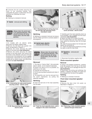 31
31 32
32 33
33 34
34 35
35 36
36 37
37 38
38 39
39 40
40 41
41 42
42 43
43 44
44 45
45 46
46 47
47 48
48 49
49 50
50 51
51 52
52 53
53 54
54 55
55 56
56 57
57 58
58 59
59 60
60 61
61 62
62 63
63 64
64 65
65 66
66 67
67 68
68 69
69 70
70 71
71 72
72 73
73 74
74 75
75 76
76 77
77 78
78 79
79 80
80 81
81 82
82 83
83 84
84 85
85 86
86 87
87 88
88 89
89 90
90 91
91 92
92 93
93 94
94 95
95 96
96 97
97 98
98 99
99 100
100 101
101 102
102 103
103 104
104 105
105 106
106 107
107 108
108 109
109 110
110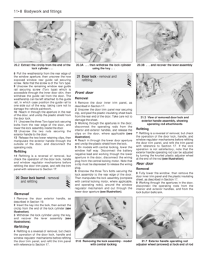 111
111 112
112 113
113 114
114 115
115 116
116 117
117 118
118 119
119 120
120 121
121 122
122 123
123 124
124 125
125 126
126 127
127 128
128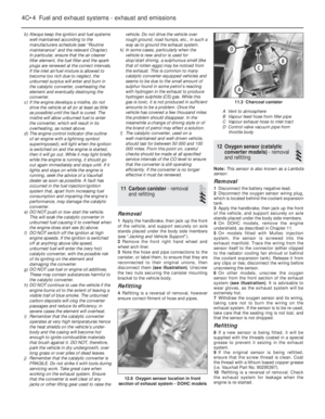 129
129 130
130 131
131 132
132 133
133 134
134 135
135 136
136 137
137 138
138 139
139 140
140 141
141 142
142 143
143 144
144 145
145 146
146 147
147 148
148 149
149 150
150 151
151 152
152 153
153 154
154 155
155 156
156 157
157 158
158 159
159 160
160 161
161 162
162 163
163 164
164 165
165 166
166 167
167 168
168 169
169 170
170 171
171 172
172 173
173 174
174 175
175 176
176 177
177 178
178 179
179 180
180 181
181 182
182 183
183 184
184 185
185 186
186 187
187 188
188 189
189 190
190 191
191 192
192 193
193 194
194 195
195 196
196 197
197 198
198 199
199 200
200 201
201 202
202 203
203 204
204 205
205 206
206 207
207 208
208 209
209 210
210 211
211 212
212 213
213 214
214 215
215 216
216 217
217 218
218 219
219 220
220 221
221 222
222 223
223 224
224 225
225 226
226 227
227 228
228 229
229 230
230 231
231 232
232 233
233 234
234 235
235 236
236 237
237 238
238 239
239 240
240 241
241 242
242 243
243 244
244 245
245 246
246 247
247 248
248 249
249 250
250 251
251 252
252 253
253 254
254 255
255 256
256 257
257 258
258 259
259 260
260 261
261 262
262 263
263 264
264 265
265 266
266 267
267 268
268 269
269 270
270 271
271 272
272 273
273 274
274 275
275 276
276 277
277 278
278 279
279 280
280 281
281 282
282 283
283 284
284 285
285 286
286 287
287 288
288 289
289 290
290 291
291 292
292 293
293 294
294 295
295 296
296 297
297 298
298 299
299 300
300 301
301 302
302 303
303 304
304 305
305 306
306 307
307 308
308 309
309 310
310 311
311 312
312 313
313 314
314 315
315 316
316 317
317 318
318 319
319 320
320 321
321 322
322 323
323 324
324 325
325 326
326 327
327 328
328 329
329 330
330 331
331 332
332 333
333 334
334 335
335 336
336 337
337 338
338 339
339 340
340 341
341 342
342 343
343 344
344 345
345 346
346 347
347 348
348 349
349 350
350 351
351 352
352 353
353 354
354 355
355 356
356 357
357 358
358 359
359 360
360 361
361 362
362 363
363 364
364 365
365 366
366 367
367 368
368 369
369 370
370 371
371 372
372 373
373 374
374 375
375 376
376 377
377 378
378 379
379 380
380 381
381 382
382 383
383 384
384 385
385 386
386 387
387 388
388 389
389 390
390 391
391 392
392 393
393 394
394 395
395 396
396 397
397 398
398 399
399 400
400 401
401 402
402 403
403 404
404 405
405 406
406 407
407 408
408 409
409 410
410 411
411 412
412 413
413 414
414 415
415 416
416 417
417 418
418 419
419 420
420 421
421 422
422 423
423 424
424 425
425 426
426 427
427 428
428 429
429 430
430 431
431 432
432 433
433 434
434 435
435 436
436 437
437 438
438 439
439 440
440 441
441 442
442 443
443 444
444 445
445 446
446 447
447 448
448 449
449 450
450 451
451 452
452 453
453 454
454 455
455 456
456 457
457 458
458 459
459 460
460 461
461 462
462 463
463 464
464 465
465 466
466 467
467 468
468 469
469 470
470 471
471 472
472 473
473 474
474 475
475 476
476 477
477 478
478 479
479 480
480 481
481 482
482 483
483 484
484 485
485 486
486 487
487 488
488 489
489 490
490 491
491 492
492 493
493 494
494 495
495 496
496 497
497 498
498 499
499 500
500 501
501 502
502 503
503 504
504 505
505 506
506 507
507 508
508 509
509 510
510 511
511 512
512 513
513 514
514 515
515 516
516 517
517 518
518 519
519 520
520 521
521 522
522 523
523 524
524