1988 OPEL CALIBRA window
[x] Cancel search: windowPage 15 of 525
12
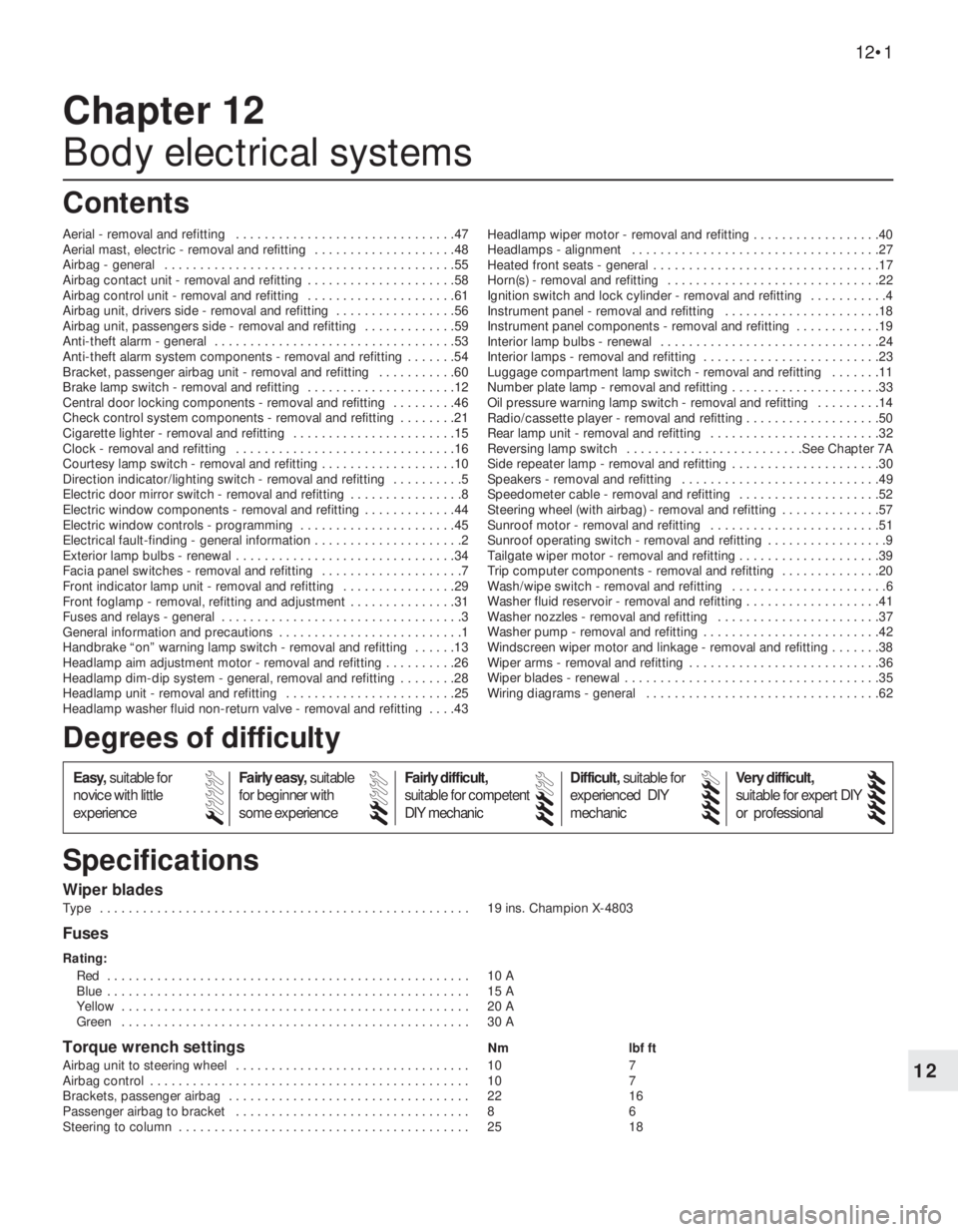
Wiper blades
Type . . . . . . . . . . . . . . . . . . . . . . . . . . . . . . . . . . . . . . . . . . . . . . . . . . . . 19 ins. Champion X-4803
Fuses
Rating:
Red . . . . . . . . . . . . . . . . . . . . . . . . . . . . . . . . . . . . . . . . . . . . . . . . . . . 10 A
Blue . . . . . . . . . . . . . . . . . . . . . . . . . . . . . . . . . . . . . . . . . . . . . . . . . . . 15 A
Yellow . . . . . . . . . . . . . . . . . . . . . . . . . . . . . . . . . . . . . . . . . . . . . . . . . 20 A
Green . . . . . . . . . . . . . . . . . . . . . . . . . . . . . . . . . . . . . . . . . . . . . . . . . 30 A
Torque wrench settingsNm lbf ft
Airbag unit to steering wheel . . . . . . . . . . . . . . . . . . . . . . . . . . . . . . . . . 10 7
Airbag control . . . . . . . . . . . . . . . . . . . . . . . . . . . . . . . . . . . . . . . . . . . . . 10 7
Brackets, passenger airbag . . . . . . . . . . . . . . . . . . . . . . . . . . . . . . . . . . 22 16
Passenger airbag to bracket . . . . . . . . . . . . . . . . . . . . . . . . . . . . . . . . . 8 6
Steering to column . . . . . . . . . . . . . . . . . . . . . . . . . . . . . . . . . . . . . . . . . 25 18
Chapter 12
Body electrical systems
Aerial - removal and refitting . . . . . . . . . . . . . . . . . . . . . . . . . . . . . . .47
Aerial mast, electric - removal and refitting . . . . . . . . . . . . . . . . . . . .48
Airbag - general . . . . . . . . . . . . . . . . . . . . . . . . . . . . . . . . . . . . . . . . .55
Airbag contact unit - removal and refitting . . . . . . . . . . . . . . . . . . . . .58
Airbag control unit - removal and refitting . . . . . . . . . . . . . . . . . . . . .61
Airbag unit, drivers side - removal and refitting . . . . . . . . . . . . . . . . .56
Airbag unit, passengers side - removal and refitting . . . . . . . . . . . . .59
Anti-theft alarm - general . . . . . . . . . . . . . . . . . . . . . . . . . . . . . . . . . .53
Anti-theft alarm system components - removal and refitting . . . . . . .54
Bracket, passenger airbag unit - removal and refitting . . . . . . . . . . .60
Brake lamp switch - removal and refitting . . . . . . . . . . . . . . . . . . . . .12
Central door locking components - removal and refitting . . . . . . . . .46
Check control system components - removal and refitting . . . . . . . .21
Cigarette lighter - removal and refitting . . . . . . . . . . . . . . . . . . . . . . .15
Clock - removal and refitting . . . . . . . . . . . . . . . . . . . . . . . . . . . . . . .16
Courtesy lamp switch - removal and refitting . . . . . . . . . . . . . . . . . . .10
Direction indicator/lighting switch - removal and refitting . . . . . . . . . .5
Electric door mirror switch - removal and refitting . . . . . . . . . . . . . . . .8
Electric window components - removal and refitting . . . . . . . . . . . . .44
Electric window controls - programming . . . . . . . . . . . . . . . . . . . . . .45
Electrical fault-finding - general information . . . . . . . . . . . . . . . . . . . . .2
Exterior lamp bulbs - renewal . . . . . . . . . . . . . . . . . . . . . . . . . . . . . . .34
Facia panel switches - removal and refitting . . . . . . . . . . . . . . . . . . . .7
Front indicator lamp unit - removal and refitting . . . . . . . . . . . . . . . .29
Front foglamp - removal, refitting and adjustment . . . . . . . . . . . . . . .31
Fuses and relays - general . . . . . . . . . . . . . . . . . . . . . . . . . . . . . . . . . .3
General information and precautions . . . . . . . . . . . . . . . . . . . . . . . . . .1
Handbrake “on” warning lamp switch - removal and refitting . . . . . .13
Headlamp aim adjustment motor - removal and refitting . . . . . . . . . .26
Headlamp dim-dip system - general, removal and refitting . . . . . . . .28
Headlamp unit - removal and refitting . . . . . . . . . . . . . . . . . . . . . . . .25
Headlamp washer fluid non-return valve - removal and refitting . . . .43Headlamp wiper motor - removal and refitting . . . . . . . . . . . . . . . . . .40
Headlamps - alignment . . . . . . . . . . . . . . . . . . . . . . . . . . . . . . . . . . .27
Heated front seats - general . . . . . . . . . . . . . . . . . . . . . . . . . . . . . . . .17
Horn(s) - removal and refitting . . . . . . . . . . . . . . . . . . . . . . . . . . . . . .22
Ignition switch and lock cylinder - removal and refitting . . . . . . . . . . .4
Instrument panel - removal and refitting . . . . . . . . . . . . . . . . . . . . . .18
Instrument panel components - removal and refitting . . . . . . . . . . . .19
Interior lamp bulbs - renewal . . . . . . . . . . . . . . . . . . . . . . . . . . . . . . .24
Interior lamps - removal and refitting . . . . . . . . . . . . . . . . . . . . . . . . .23
Luggage compartment lamp switch - removal and refitting . . . . . . .11
Number plate lamp - removal and refitting . . . . . . . . . . . . . . . . . . . . .33
Oil pressure warning lamp switch - removal and refitting . . . . . . . . .14
Radio/cassette player - removal and refitting . . . . . . . . . . . . . . . . . . .50
Rear lamp unit - removal and refitting . . . . . . . . . . . . . . . . . . . . . . . .32
Reversing lamp switch . . . . . . . . . . . . . . . . . . . . . . . . .See Chapter 7A
Side repeater lamp - removal and refitting . . . . . . . . . . . . . . . . . . . . .30
Speakers - removal and refitting . . . . . . . . . . . . . . . . . . . . . . . . . . . .49
Speedometer cable - removal and refitting . . . . . . . . . . . . . . . . . . . .52
Steering wheel (with airbag) - removal and refitting . . . . . . . . . . . . . .57
Sunroof motor - removal and refitting . . . . . . . . . . . . . . . . . . . . . . . .51
Sunroof operating switch - removal and refitting . . . . . . . . . . . . . . . . .9
Tailgate wiper motor - removal and refitting . . . . . . . . . . . . . . . . . . . .39
Trip computer components - removal and refitting . . . . . . . . . . . . . .20
Wash/wipe switch - removal and refitting . . . . . . . . . . . . . . . . . . . . . .6
Washer fluid reservoir - removal and refitting . . . . . . . . . . . . . . . . . . .41
Washer nozzles - removal and refitting . . . . . . . . . . . . . . . . . . . . . . .37
Washer pump - removal and refitting . . . . . . . . . . . . . . . . . . . . . . . . .42
Windscreen wiper motor and linkage - removal and refitting . . . . . . .38
Wiper arms - removal and refitting . . . . . . . . . . . . . . . . . . . . . . . . . . .36
Wiper blades - renewal . . . . . . . . . . . . . . . . . . . . . . . . . . . . . . . . . . . .35
Wiring diagrams - general . . . . . . . . . . . . . . . . . . . . . . . . . . . . . . . . .62
12•1
Specifications Contents
Easy,suitable for
novice with little
experienceFairly easy,suitable
for beginner with
some experienceFairly difficult,
suitable for competent
DIY mechanic
Difficult,suitable for
experienced DIY
mechanicVery difficult,
suitable for expert DIY
or professional
Degrees of difficulty
54321
Page 27 of 525
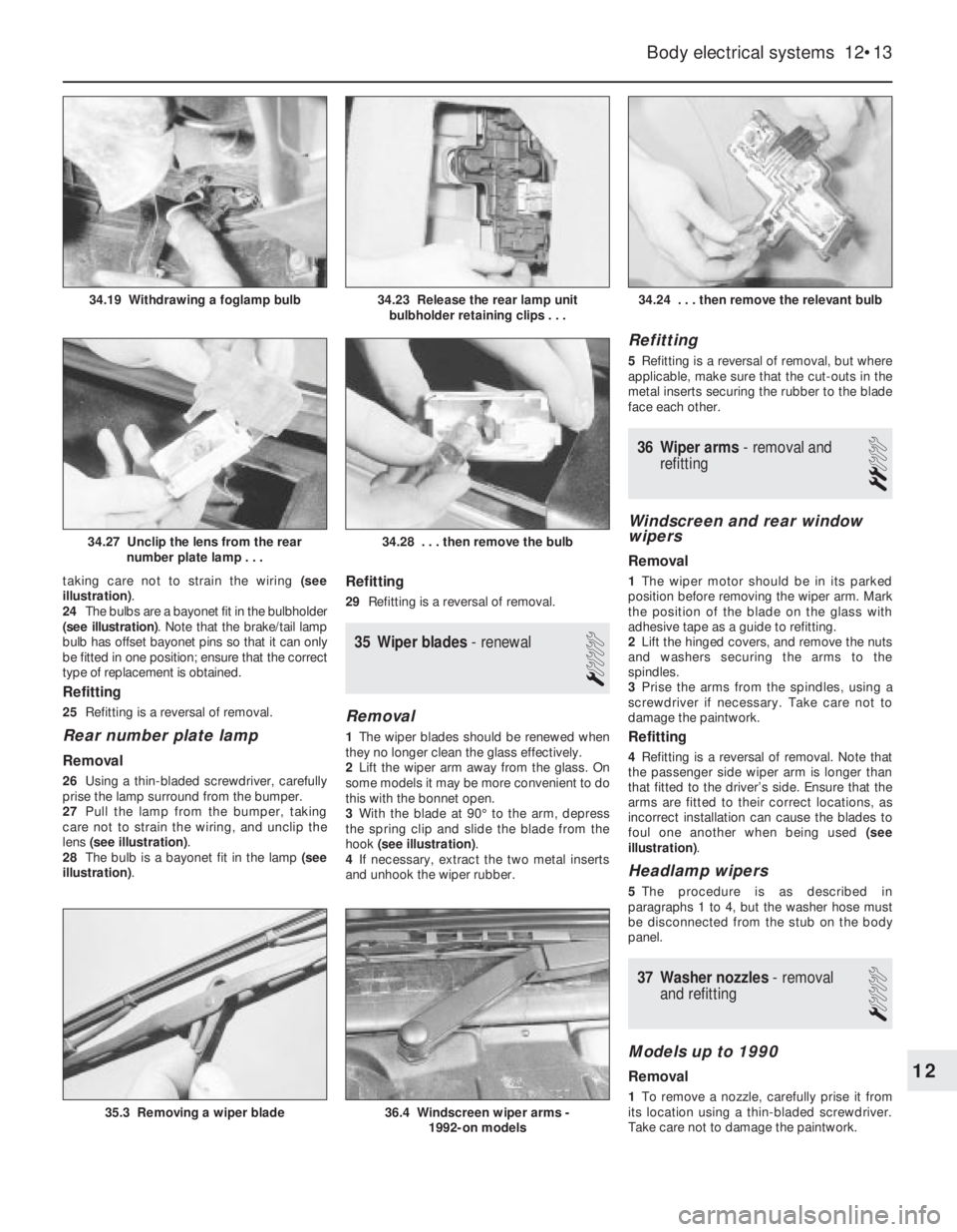
taking care not to strain the wiring (see
illustration).
24The bulbs are a bayonet fit in the bulbholder
(see illustration). Note that the brake/tail lamp
bulb has offset bayonet pins so that it can only
be fitted in one position; ensure that the correct
type of replacement is obtained.
Refitting
25Refitting is a reversal of removal.
Rear number plate lamp
Removal
26Using a thin-bladed screwdriver, carefully
prise the lamp surround from the bumper.
27Pull the lamp from the bumper, taking
care not to strain the wiring, and unclip the
lens (see illustration).
28The bulb is a bayonet fit in the lamp (see
illustration).
Refitting
29Refitting is a reversal of removal.
35Wiper blades -renewal
1
Removal
1The wiper blades should be renewed when
they no longer clean the glass effectively.
2Lift the wiper arm away from the glass. On
some models it may be more convenient to do
this with the bonnet open.
3With the blade at 90°to the arm, depress
the spring clip and slide the blade from the
hook (see illustration).
4If necessary, extract the two metal inserts
and unhook the wiper rubber.
Refitting
5Refitting is a reversal of removal, but where
applicable, make sure that the cut-outs in the
metal inserts securing the rubber to the blade
face each other.
36Wiper arms - removal and
refitting
2
Windscreen and rear window
wipers
Removal
1The wiper motor should be in its parked
position before removing the wiper arm. Mark
the position of the blade on the glass with
adhesive tape as a guide to refitting.
2Lift the hinged covers, and remove the nuts
and washers securing the arms to the
spindles.
3Prise the arms from the spindles, using a
screwdriver if necessary. Take care not to
damage the paintwork.
Refitting
4Refitting is a reversal of removal. Note that
the passenger side wiper arm is longer than
that fitted to the driver’s side. Ensure that the
arms are fitted to their correct locations, as
incorrect installation can cause the blades to
foul one another when being used (see
illustration).
Headlamp wipers
5The procedure is as described in
paragraphs 1 to 4, but the washer hose must
be disconnected from the stub on the body
panel.
37Washer nozzles - removal
and refitting
1
Models up to 1990
Removal
1To remove a nozzle, carefully prise it from
its location using a thin-bladed screwdriver.
Take care not to damage the paintwork.
Body electrical systems 12•13
34.24 . . . then remove the relevant bulb
36.4 Windscreen wiper arms -
1992-on models35.3 Removing a wiper blade
34.28 . . . then remove the bulb34.27 Unclip the lens from the rear
number plate lamp . . .
34.23 Release the rear lamp unit
bulbholder retaining clips . . .34.19 Withdrawing a foglamp bulb
12
Page 29 of 525
41Washer fluid reservoir -
removal and refitting
2
1Disconnect the battery negative lead.
Models without headlamp wash
Removal
2Disconnect the wiring from the washer
pump.
3Disconnect the washer fluid hose from the
pump. Be prepared for fluid spillage.
4Remove the screw(s) securing the reservoir
to the body, and withdraw the reservoir.
Refitting
5Refitting is a reversal of removal.
Models with headlamp wash
Removal
6On models with headlamp wash, the
reservoir is in two sections, the upper section,
which can be removed from the engine
compartment, and the lower section, which
must be removed from under the wheel arch.
7Disconnect the wiring from the headlamp
wash non-return valve in the top of the
reservoir.
8Disconnect the washer fluid hoses from the
non-return valve. Be prepared for fluid spillage.
9Remove the screw securing the upper
section of the reservoir to the wing panel.
10Loosen the plastic collar securing the
upper section of the reservoir to the lower
section, then withdraw the upper section of
the reservoir from the engine compartment.
11To remove the lower section of the
reservoir, continue as follows.
12Apply the handbrake, then jack up the
front of the vehicle, and support on axle
stands (see “Jacking and Vehicle Support”)
positioned under the body side members.
13Remove the securing screws, and
withdraw the plastic cover from thebumper/front wing to expose the lower
section of the reservoir.
14Remove the horns, (Section 22).
15Remove the wheel arch liner, (Chapter 11).
16Disconnect the wiring and the fluid hoses
from the washer pump. Be prepared for fluid
spillage.
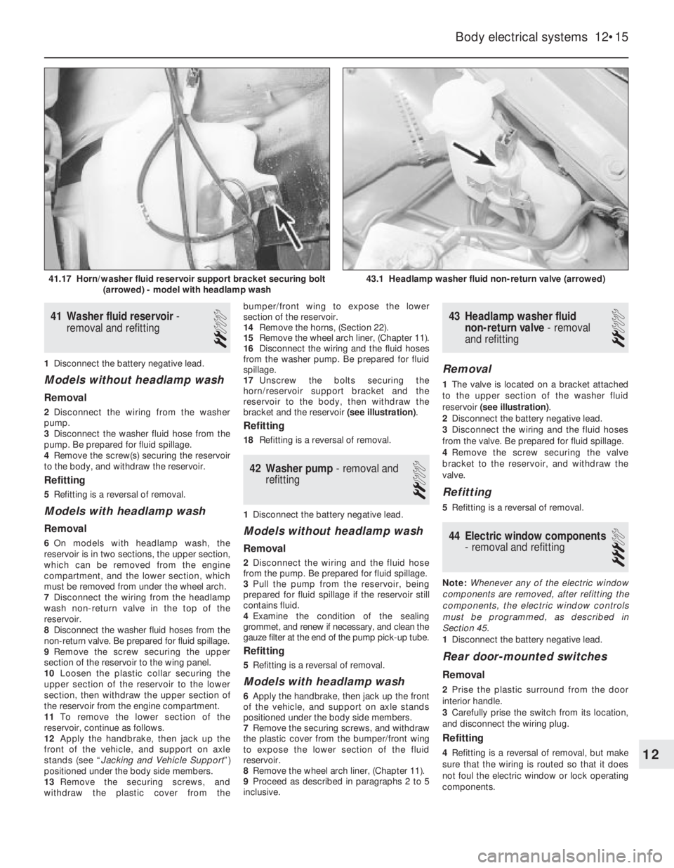
17Unscrew the bolts securing the
horn/reservoir support bracket and the
reservoir to the body, then withdraw the
bracket and the reservoir (see illustration).
Refitting
18Refitting is a reversal of removal.
42Washer pump -removal and
refitting
2
1Disconnect the battery negative lead.
Models without headlamp wash
Removal
2Disconnect the wiring and the fluid hose
from the pump. Be prepared for fluid spillage.
3Pull the pump from the reservoir, being
prepared for fluid spillage if the reservoir still
contains fluid.
4Examine the condition of the sealing
grommet, and renew if necessary, and clean the
gauze filter at the end of the pump pick-up tube.
Refitting
5Refitting is a reversal of removal.
Models with headlamp wash
6Apply the handbrake, then jack up the front
of the vehicle, and support on axle stands
positioned under the body side members.
7Remove the securing screws, and withdraw
the plastic cover from the bumper/front wing
to expose the lower section of the fluid
reservoir.
8Remove the wheel arch liner, (Chapter 11).
9Proceed as described in paragraphs 2 to 5
inclusive.
43Headlamp washer fluid
non-return valve -removal
and refitting
2
Removal
1The valve is located on a bracket attached
to the upper section of the washer fluid
reservoir (see illustration).
2Disconnect the battery negative lead.
3Disconnect the wiring and the fluid hoses
from the valve. Be prepared for fluid spillage.
4Remove the screw securing the valve
bracket to the reservoir, and withdraw the
valve.
Refitting
5Refitting is a reversal of removal.
44Electric window components
- removal and refitting
3
Note: Whenever any of the electric window
components are removed, after refitting the
components, the electric window controls
must be programmed, as described in
Section 45.
1Disconnect the battery negative lead.
Rear door-mounted switches
Removal
2Prise the plastic surround from the door
interior handle.
3Carefully prise the switch from its location,
and disconnect the wiring plug.
Refitting
4Refitting is a reversal of removal, but make
sure that the wiring is routed so that it does
not foul the electric window or lock operating
components.
Body electrical systems 12•15
43.1 Headlamp washer fluid non-return valve (arrowed)41.17 Horn/washer fluid reservoir support bracket securing bolt
(arrowed) - model with headlamp wash
12
Page 30 of 525
Centre console-mounted
switches
Removal
5The switches must be removed as a
complete assembly, and cannot be
dismantled. If one of the switches is faulty, the
complete assembly must be renewed.
6Remove the rear section of the centre
console, as described in Chapter 11.
7Release the securing clips, and withdraw
the switch assembly through the top of the
centre console.
Refitting
8Refitting is a reversal of removal.
Operating motors
9Remove the door window regulator, as
described in Chapter 11.
10To remove the motor assembly from the
front door window regulator, unscrew the
three motor securing nuts, and the single
screw securing the pulse pick-up unit to the
regulator assembly. Withdraw the motor,
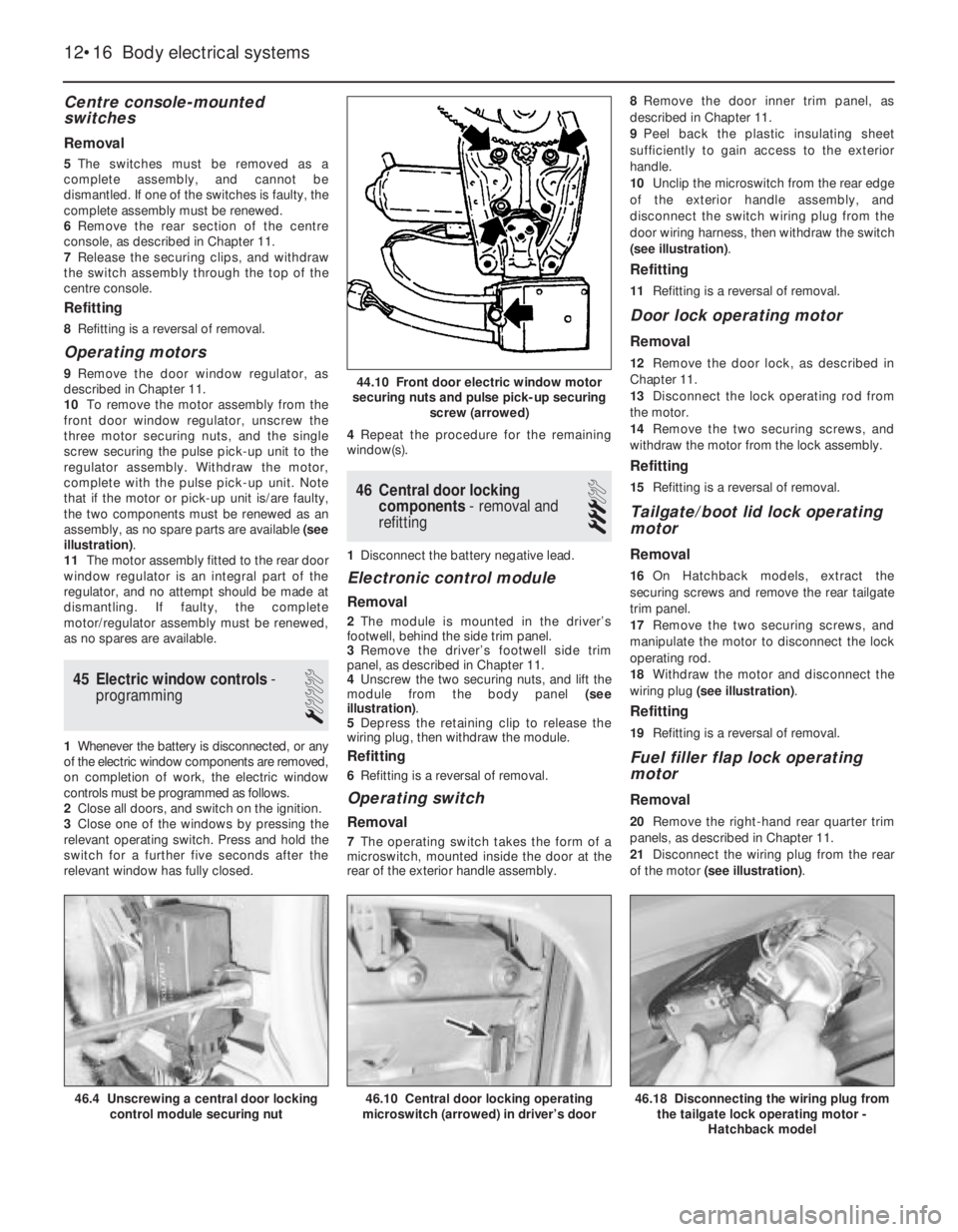
complete with the pulse pick-up unit. Note
that if the motor or pick-up unit is/are faulty,
the two components must be renewed as an
assembly, as no spare parts are available (see
illustration).
11The motor assembly fitted to the rear door
window regulator is an integral part of the
regulator, and no attempt should be made at
dismantling. If faulty, the complete
motor/regulator assembly must be renewed,
as no spares are available.
45Electric window controls -
programming
1
1Whenever the battery is disconnected, or any
of the electric window components are removed,
on completion of work, the electric window
controls must be programmed as follows.
2Close all doors, and switch on the ignition.
3Close one of the windows by pressing the
relevant operating switch. Press and hold the
switch for a further five seconds after the
relevant window has fully closed.4Repeat the procedure for the remaining
window(s).
46Central door locking
components -removal and
refitting
3
1Disconnect the battery negative lead.
Electronic control module
Removal
2The module is mounted in the driver’s
footwell, behind the side trim panel.
3Remove the driver’s footwell side trim
panel, as described in Chapter 11.
4Unscrew the two securing nuts, and lift the
module from the body panel (see
illustration).
5Depress the retaining clip to release the
wiring plug, then withdraw the module.
Refitting
6Refitting is a reversal of removal.
Operating switch
Removal
7The operating switch takes the form of a
microswitch, mounted inside the door at the
rear of the exterior handle assembly.8Remove the door inner trim panel, as
described in Chapter 11.
9Peel back the plastic insulating sheet
sufficiently to gain access to the exterior
handle.
10Unclip the microswitch from the rear edge
of the exterior handle assembly, and
disconnect the switch wiring plug from the
door wiring harness, then withdraw the switch
(see illustration).
Refitting
11Refitting is a reversal of removal.
Door lock operating motor
Removal
12Remove the door lock, as described in
Chapter 11.
13Disconnect the lock operating rod from
the motor.
14Remove the two securing screws, and
withdraw the motor from the lock assembly.
Refitting
15Refitting is a reversal of removal.
Tailgate/boot lid lock operating
motor
Removal
16On Hatchback models, extract the
securing screws and remove the rear tailgate
trim panel.
17Remove the two securing screws, and
manipulate the motor to disconnect the lock
operating rod.
18Withdraw the motor and disconnect the
wiring plug (see illustration).
Refitting
19Refitting is a reversal of removal.
Fuel filler flap lock operating
motor
Removal
20Remove the right-hand rear quarter trim
panels, as described in Chapter 11.
21Disconnect the wiring plug from the rear
of the motor (see illustration).
12•16Body electrical systems
44.10 Front door electric window motor
securing nuts and pulse pick-up securing
screw (arrowed)
46.10 Central door locking operating
microswitch (arrowed) in driver’s door46.18 Disconnecting the wiring plug from
the tailgate lock operating motor -
Hatchback model46.4 Unscrewing a central door locking
control module securing nut
Page 36 of 525

12•22Body electrical systems
Explanations of abbreviations used in wiring diagrams
ABSAnti-lock braking system
ACAir conditioning
AZVTrailer hitch
ATAutomatic transmission
ATCAutomatic temperature control
BRTrip (on-board) computer
CCCheck control system
CRCCruise control
DDiesel
DSTheft protection
DTTurbo Diesel
DWAAnti-theft warning system
DZMTachometer
EFCElectric folding roof (Convertible)
EKSPinch guard (electric windows)
EMPRadio
EUREuronorm (emission control standard)
engine
EZ + ElPlus ignition system (with self-
diagnosis)
EZVEcotronic
FHElectric windows
GBGreat Britain
HSHeated rear window
HWRear window wiper
HZGHeating
HRLLuggage compartment lampINSInstrument panel
IRLCourtesy lamps
KATCatalytic converter
KBSWiring harness
KVContact breaker distributor
L3.1Bosch Jetronic fuel injection system
LCDLiquid crystal display (LCD)
instruments
LHDLeft-hand drive
4WDFour-wheel-drive
LWRHeadlamp aim adjustment
M1.5Bosch Motronic M1.5 engine
management system
M2.5Bosch Motronic M2.5 engine
management system
MOTMotronic (general)
MTManual gearbox
MULMultec fuel injection system
NNorway
NSFront foglamps
NSLRear foglamps
OELOil level/pressure check system
OPTOptional equipment
PBSLPark and brake shift block
(automatic transmission, selector
lever in position ‘P’)P/NPark/neutral (automatic transmission)
POTPotentiometer
RCRear suspension level control
system
RFSReversing lamps
RHDRight-hand drive
SSweden
SDSunroof
SHHeated seats
SRAHeadlamp washers and wipers
TANKFuel level sender unit
TDTurbo Diesel
TEMPTemperature gauge
TFLDaytime driving lamps
TKSCourtesy lamp (door pillar) switches
TSZITransistorised ignition (inductive-
triggered) system
VGSCarburettor
WEGOdometer frequency/roadspeed
sensor
WHRRear suspension level control
system
WSWarning buzzer
ZVCentral locking
ZYLCylinder
Colour codes
BLBlue
HBLLight blue
BRBrown
GEYellow
GRGrey
GNGreenRTRed
WSWhite
SWBlack
LILilac
VIViolet
Wiring identification
Example: GEWS 1.5
GE -Wire basic colour
WS -Wire tracer colour
1.5 -Wire cross-section in mm
2
Note: Not all items shown are fitted to all models. Refer to Section 62 (Chapter 12) for details of diagram usage.
Page 37 of 525

Wiring diagrams 12•23
12
Key to wiring diagrams for 1989 models
E1Sidelamp - left406
E2Tail lamp -left302, 380, 407
E3Number plate lamp413
E4Side lamp right409
E5Tail lamp right382, 410
E6Engine compartment lamp416
E7Headlamp main beam - left437
E8Headlampmain beam - right438
E9Headlampdipped beam - left384, 439
E10Headlamp dipped beam - right386, 440
E11Instrument illumination lamps328 to 329
E12Gear selector lever illumination lamp (automatics)799
E13Luggage compartment lamp485
E14Courtesy lamp487
E15Glovebox lamp599
E16Cigarette lighter illumination lamp598
E17Reversing lamp - left497
E18Reversing lamp - right498
E19Heated rearwindow572
E20Front foglamp -left448
E21Front foglamp - right447
E24Rear foglamp - left454
E25Seat heater -front left575
E30Seat heater - front right579
E32Clock illumination lamp552
E38Trip computer illumination lamp539
E39Rear foglamp - right455
E41Courtesy lamp (with delay)488 to 490
E50Kerb lamp - driver’s door635
E51Kerb lamp - passenger door653
F1 toFuse (in fusebox)Various
F30
F32Fuse - mixture preheating (not UK)232
F33Fuse - electronic carburettor (not UK)201
F34Fuse (in relay box, engine compartment)834
F35Voltage stabiliser302
F36Fuse - fuel filter heating (Diesel models)866
G1Battery101
G2Alternator110
G3Battery - Diesel models846
G6Alternator - Diesel models850 to 852
H2Horn591
H3Direction indicator warning lamp318, 320
H4Oil pressure warning lamp310
H5Brake fluid level warning lamp313
H6Hazard warning flasher warning lamp470
H7Alternator charge warning lamp310
H8Headlamp main beam warning lamp322
H9Brake lamp - left388
H10Brake lamp - right390H11Direction indicator lamp - front left472
H12Direction indicatorlamp - rear left473
H13Direction indicator lamp - front right481
H14Direction indicator lamp - rear right482
H16Glow plug warning lamp (Diesel models)323
H17Trailer direction indicator warning lamp321
H18Horns (twin)592, 593
H19Headlamps-on warning buzzer494, 495
H21Handbrake-on warning lamp315
H23Radio/cassette player585, 586
H25Door mirror heater warning lamp678
H26ABS warning lamp319
H30Engine fault warning lamp324
H33Direction indicator side repeater lamp - left476
H34Direction indicator side repeater lamp - right478
H42Automatic transmission warning lamp325
H45Four-wheel-drive warning lamp327
H46Catalytic converter temperature warning lamp (not UK)329
K1Relay-heated rear window571 to 572
K5Relay - front foglamps448 to 450
K6Relay - air conditioning (not UK)801 to 802
K7Relay - air conditioning blower (not UK)808 to 809
K8Relay - intermittent windscreen wipe503 to 506
K9Relay - headlamp wash522 to 523
K10Relay - direction indicator/hazard warning flashers467 to 469
K20HEI ignition control unit122 to 124
K25Relay - glow plugs (Diesel models)856 to 859
K30Relay - intermittent rear window wipe515 to 517
K35Relay - door mirror heater683 to 685
K37Central locking control unit606 to 612
K45Relay - mixture preheating (not UK)231 to 232
K47Relay - surge arrester (ABS)702 to 703
K50ABS control unit707 to 721
K51Relay - cooling fan830 to 831
K54Electronic carburettor control unit (not UK)203 to 226
K55Relay - electronic carburettor (not UK)203 to 206
K57Fuel injection control unit (not UK)139 to 161
K58Relay -fuel pump (not UK)162 to 163
K59Relay - daytime running lamps (not UK)420 to 426
K61Motronic M4.1 control unit170 to 194
K62Dim-dip control unit428 to 432
K63Relay - horn593 to 594
K64Relay - air conditioning blower (not UK)802 to 803
K67Relay -cooling fan827 to 828
K68Relay -fuel injection system294 to 299, 196 to 199
K69Motronic M2.5 control unit267 to 297
K71Ride control unit (not UK)739 to 754
K80Relay -fuel filter heater (Diesel models)865 to 866
K82Relay - engine revolution862 to 863
K83Four-wheel-drive control unit725 to 731 NoDescriptionTrackNoDescriptionTrack
Page 38 of 525
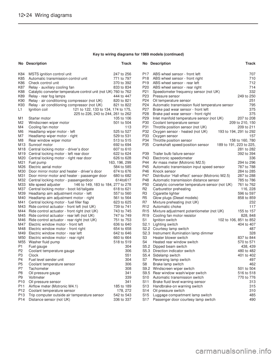
12•24Wiring diagrams
K84MSTS ignition control unit247 to 256
K85Automatic transmission control unit771 to 797
K86Check control unit370 to 392
K87Relay - auxiliary cooling fan833 to 834
K88Catalytic converter temperature control unit (not UK)760 to 762
K89Relay - rear fog lamps444 to 447
K90Relay - air conditioning compressor (not UK)820 to 821
K93Relay - air conditioning compressor (not UK)821 to 822
L1Ignition coil121 to 122, 133 to 134, 174 to 175,
225 to 226, 243 to 244, 261 to 262
M1Starter motor105 to 106
M2Windscreen wiper motor501 to 504
M4Cooling fan motor113
M6Headlamp wiper motor -left525 to 527
M7Headlamp wiper motor - right529 to 531
M8Rear window wiper motor513 to 515
M13Sunroof motor692 to 694
M18Central locking motor - driver’s door607 to 610
M19Central locking motor - left rear door622 to 624
M20Central locking motor - right rear door626 to 628
M21Fuel pump163, 196, 299
M26Electric aerial motor584 to 585
M30Door mirror motor and heater - driver’s door674 to 676
M31Door mirror motor and heater - passenger door680 to 682
M32Central locking motor - passengerdoor614to617
M33Idle speed adjuster146 to 149, 183 to 184, 277 to 278
M37Central locking motor - boot lid/tailgate618 to 621
M39Headlamp aim adjustment motor -left557 to 560
M40Headlamp aim adjustment motor - right561 to 564
M41Central locking motor - fuel filler flap623 to 625
M43Ride control actuator - front left (not UK)739 to 741
M44Ride control actuator - front right (not UK)743 to 745
M45Ride control actuator -rear left (not UK)747 to 749
M46Ride control actuator - rear right (not UK)751 to 753
M47Electric window motor - front left636 to 640
M48Electric window motor - front right654 to 658
M49Electric window motor - rear left642 to 646
M50Electric window motor - rear right660 to 664
M55Washer fluid pump518 to 519
P1Fuel gauge304
P2Coolant temperature gauge306
P3Clock551
P4Fuel level sender unit304
P5Coolant temperature sensor306
P7Tachometer308
P8Oil pressure gauge341
P9Voltmeter339
P10Oil pressure sensor341
P11Airflow meter (Motronic M4.1)185 to 189
P12Coolant temperature sensor178, 272
P13Trip computer outside air temperature sensor542 to 543
P14Distance sensor (not UK)336 to 337P17ABS wheel sensor - front left707
P18ABS wheel sensor -front right710
P19ABS wheel sensor -rear left712
P20ABS wheel sensor - rear right714
P21Speedometer frequency sensor (not UK)332
P23Pressure sensor 249 to 250
P24Oil temperature sensor251
P24Automatic transmission fluid temperature sensor795
P27Brake pad wear sensor - front left375
P28Brake pad wear sensor - front right375
P29Inlet manifold temperature sensor (not UK)207 to 208
P30Coolant temperature sensor209 to 210, 150
P31Throttle position sensor (not UK)209 to 211
P32Oxygen sensor - heated (not UK)193 to 194, 291 to 292
P33Oxygen sensor157
P34Throttle position sensor158 to 160, 780
P35Crankshaft speed/position sensor189 to 191, 223 to 225,
281 to 282
P39Trailer bulb failure sensor392 to 394
P43Electronic speedometer336
P44Air mass meter (Motronic M2.5)294 to 296
P45Automatic transmission input speed sensor787 to 788
P46Knock sensor284 to 285
P47Distributor ‘Hall-effect’ sensor (Motronic M2.5)287 to 288
P48Automatic transmission distance sensor785 to 786
P50Catalytic converter temperature sensor (not UK)761 to 762
R2Carburettor preheating116, 228
R3Cigarette lighter596 to 597
R5Glow plugs (Diesel models)858 to 859
R7Mixture preheating (not UK)232
R12Automatic choke117
R15Mixture adjustment potentiometer (not UK)155 to 157
R19Cooling fan motor resistor828, 848
S1Ignition switch102 to 106, 851 to 852
S2.1Lighting switch404 to 407
S2.2Courtesy lamp switch487
S2.3Instrument illumination lamp dimmer328
S3Heater blower switch837 to 844
S4Heated rear window switch570 to 571
S5.2Dipped beam switch438, 439
S5.3Direction indicator switch480 to 482
S5.4Sidelamp switch401 to 402
S7Reversing lamp switch497
S8Brake lamp switch462
S9.2Windscreen wiper switch501 to 504
S9.5Rear window wash/wiper switch516 to 518
S10Automatic transmission switch770 to 776
S11Brake fluid level warning sensor313
S13Handbrake-on warning switch315
S14Oil pressure switch310
S15Luggage compartment lamp switch485
S17Passenger door courtesy lamp switch490 Key to wiring diagrams for 1989 models (continued)
NoDescriptionTrackNoDescriptionTrack
Page 39 of 525
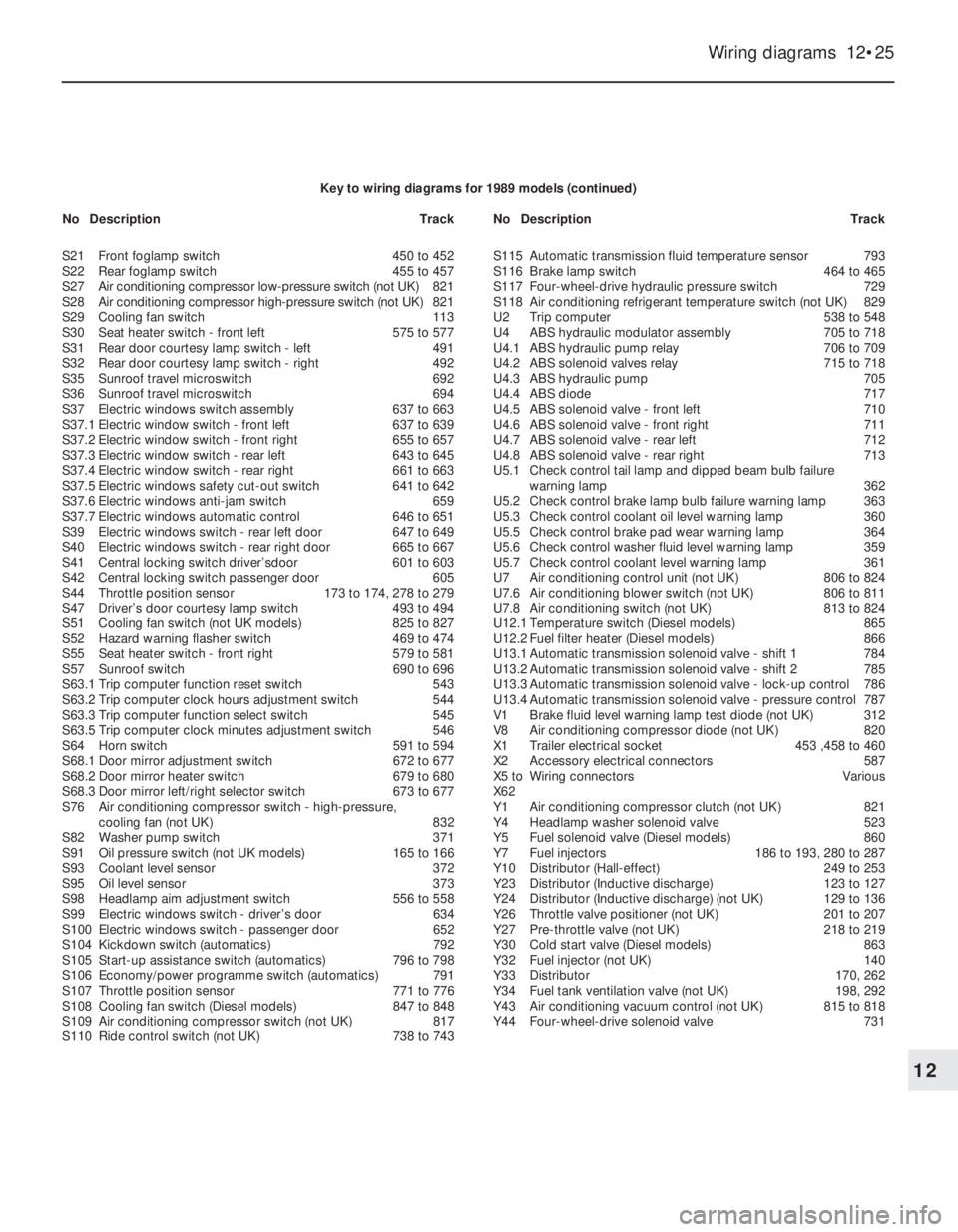
Wiring diagrams 12•25
12
Key to wiring diagrams for 1989 models (continued)
S21Front foglamp switch450 to 452
S22Rear foglamp switch455 to 457
S27Air conditioning compressor low-pressure switch (not UK)821
S28Air conditioning compressor high-pressure switch (not UK)821
S29Cooling fan switch113
S30Seat heater switch - front left575 to 577
S31Rear door courtesy lamp switch - left491
S32Rear door courtesy lamp switch - right492
S35Sunroof travel microswitch692
S36Sunroof travel microswitch694
S37Electric windows switch assembly637 to 663
S37.1Electric window switch - front left637 to 639
S37.2Electric window switch - front right655 to 657
S37.3Electric window switch - rear left643 to 645
S37.4Electric window switch - rear right661 to 663
S37.5Electric windows safety cut-out switch641 to 642
S37.6Electric windows anti-jam switch659
S37.7Electric windows automatic control646 to 651
S39Electric windows switch - rear left door647 to 649
S40Electric windows switch - rear right door665 to 667
S41Central locking switch driver’sdoor601 to 603
S42Central locking switch passenger door605
S44Throttle position sensor173 to 174, 278 to 279
S47Driver’s door courtesy lamp switch493 to 494
S51Cooling fan switch (not UK models)825 to 827
S52Hazard warning flasher switch469 to 474
S55Seat heater switch - front right579 to 581
S57Sunroof switch690 to 696
S63.1Trip computer function reset switch543
S63.2Trip computer clock hours adjustment switch544
S63.3Trip computer function select switch545
S63.5Trip computer clock minutes adjustment switch546
S64Horn switch591 to 594
S68.1Door mirror adjustment switch672 to 677
S68.2Door mirror heater switch679 to 680
S68.3Door mirror left/right selector switch673 to 677
S76Air conditioning compressor switch -high-pressure,
cooling fan (not UK)832
S82Washer pump switch371
S91Oil pressure switch (not UK models)165 to 166
S93Coolant level sensor372
S95Oil level sensor373
S98Headlamp aim adjustment switch556 to 558
S99Electric windows switch - driver’s door634
S100Electric windows switch -passenger door652
S104Kickdown switch (automatics)792
S105Start-up assistance switch (automatics)796 to 798
S106Economy/power programme switch (automatics)791
S107Throttle position sensor 771 to 776
S108Cooling fan switch (Diesel models)847 to 848
S109Air conditioning compressor switch (not UK)817
S110Ride control switch (not UK)738 to 743S115Automatic transmission fluid temperature sensor793
S116Brake lamp switch464 to 465
S117Four-wheel-drive hydraulic pressure switch729
S118Air conditioning refrigerant temperature switch (not UK)829
U2Trip computer538 to 548
U4ABS hydraulic modulator assembly705 to 718
U4.1ABS hydraulic pump relay706 to 709
U4.2ABS solenoid valves relay715 to 718
U4.3ABS hydraulic pump705
U4.4ABS diode717
U4.5ABS solenoid valve - front left710
U4.6ABS solenoid valve - front right711
U4.7ABS solenoid valve - rear left712
U4.8ABS solenoid valve - rear right713
U5.1Check control tail lamp and dipped beam bulb failure
warning lamp362
U5.2Check control brake lamp bulb failure warning lamp 363
U5.3Check control coolant oil level warning lamp360
U5.5Check control brake pad wear warning lamp364
U5.6Check control washer fluid level warning lamp359
U5.7Check control coolant level warning lamp361
U7Air conditioning control unit (not UK)806 to 824
U7.6Air conditioning blower switch (not UK)806 to 811
U7.8Air conditioning switch (not UK)813 to 824
U12.1Temperature switch (Diesel models)865
U12.2Fuel filter heater (Diesel models)866
U13.1Automatic transmission solenoid valve -shift 1784
U13.2Automatic transmission solenoid valve - shift 2785
U13.3Automatic transmission solenoid valve - lock-up control786
U13.4Automatic transmission solenoid valve - pressure control787
V1Brake fluid level warning lamp test diode (not UK)312
V8 Air conditioning compressor diode (not UK)820
X1Trailer electrical socket453 ,458 to 460
X2Accessory electrical connectors587
X5 toWiring connectorsVarious
X62
Y1Air conditioning compressor clutch (not UK)821
Y4Headlamp washer solenoid valve523
Y5Fuel solenoid valve (Diesel models)860
Y7Fuel injectors186 to 193, 280 to 287
Y10Distributor (Hall-effect)249 to 253
Y23Distributor (Inductive discharge)123 to 127
Y24Distributor (Inductive discharge) (not UK)129 to 136
Y26Throttle valve positioner (not UK)201 to 207
Y27Pre-throttle valve (not UK)218 to 219
Y30Cold start valve (Diesel models)863
Y32Fuel injector (not UK)140
Y33Distributor170, 262
Y34Fuel tank ventilation valve (not UK)198, 292
Y43Air conditioning vacuum control (not UK)815 to 818
Y44Four-wheel-drive solenoid valve731 NoDescriptionTrackNoDescriptionTrack