1988 OPEL CALIBRA window
[x] Cancel search: windowPage 109 of 525
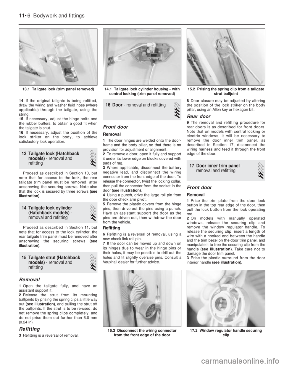
14If the original tailgate is being refitted,
draw the wiring and washer fluid hose (where
applicable) through the tailgate, using the
string.
15If necessary, adjust the hinge bolts and
the rubber buffers, to obtain a good fit when
the tailgate is shut.
16If necessary, adjust the position of the
lock striker on the body, to achieve
satisfactory lock operation.
13Tailgate lock (Hatchback
models) - removal and
refitting
2
Proceed as described in Section 10, but
note that for access to the lock, the rear
tailgate trim panel must be removed, after
unscrewing the securing screws. Note also
that the lock is secured by three screws (see
illustration).
14Tailgate lock cylinder
(Hatchback models) -
removal and refitting
2
Proceed as described in Section 11, but
note that for access to the lock cylinder, the
rear tailgate trim panel must be removed after
unscrewing the securing screws (see
illustration).
15Tailgate strut (Hatchback
models) - removal and
refitting
2
Removal
1Open the tailgate fully, and have an
assistant support it.
2Release the strut from its mounting
balljoints by prising the spring clips a little way
out (see illustration), and pulling the strut off
the balljoints. If the strut is to be re-used, do
not remove the spring clips completely, and
do not prise them out further than 6.0 mm
(0.24 in).
Refitting
3Refitting is a reversal of removal.
16Door - removal and refitting
3
Front door
Removal
1The door hinges are welded onto the door-
frame and the body pillar, so that there is no
provision for adjustment or alignment.
2To remove a door, open it fully and support
it under its lower edge on blocks covered with
pads of rag.
3Where applicable, disconnect the battery
negative lead, and disconnect the wiring
connector from the front edge of the door. To
release the connector, twist the locking collar,
then pull the connector from the socket in the
door (see illustration).
4Using a punch, drive the large roll pin from
the door check arm pivot.
5Remove the plastic covers from the hinge
pins, then drive out the pins using a punch.
Have an assistant support the door as the
pins are driven out, then withdraw the door
from the vehicle.
Refitting
6Refitting is a reversal of removal, using a
new check link roll pin.
7If the door can be moved up and down on
its hinges due to wear in the hinge pins or
their holes, it may be possible to drill out the
holes and fit slightly oversize pins. Consult a
Vauxhall dealer for further advice.8Door closure may be adjusted by altering
the position of the lock striker on the body
pillar, using an Allen key or hexagon bit.
Rear door
9The removal and refitting procedure for
rear doors is as described for front doors.
Note that on models with central locking or
electric windows, it will be necessary to
remove the door inner trim panel, as
described in Section 17, disconnect the
wiring harness and feed it through the front
edge of the door.
17Door inner trim panel -
removal and refitting
2
Front door
Removal
1Prise the trim plate from the door lock
button in the top rear edge of the door, then
pull the lock button from the lock operating
rod.
2On models with manually operated
windows, release the securing clip and
remove the window regulator handle. To
release the securing clip, insert a length of
wire with a hooked end between the handle
and the trim bezel on the door trim panel, and
manipulate it to free the securing clip from the
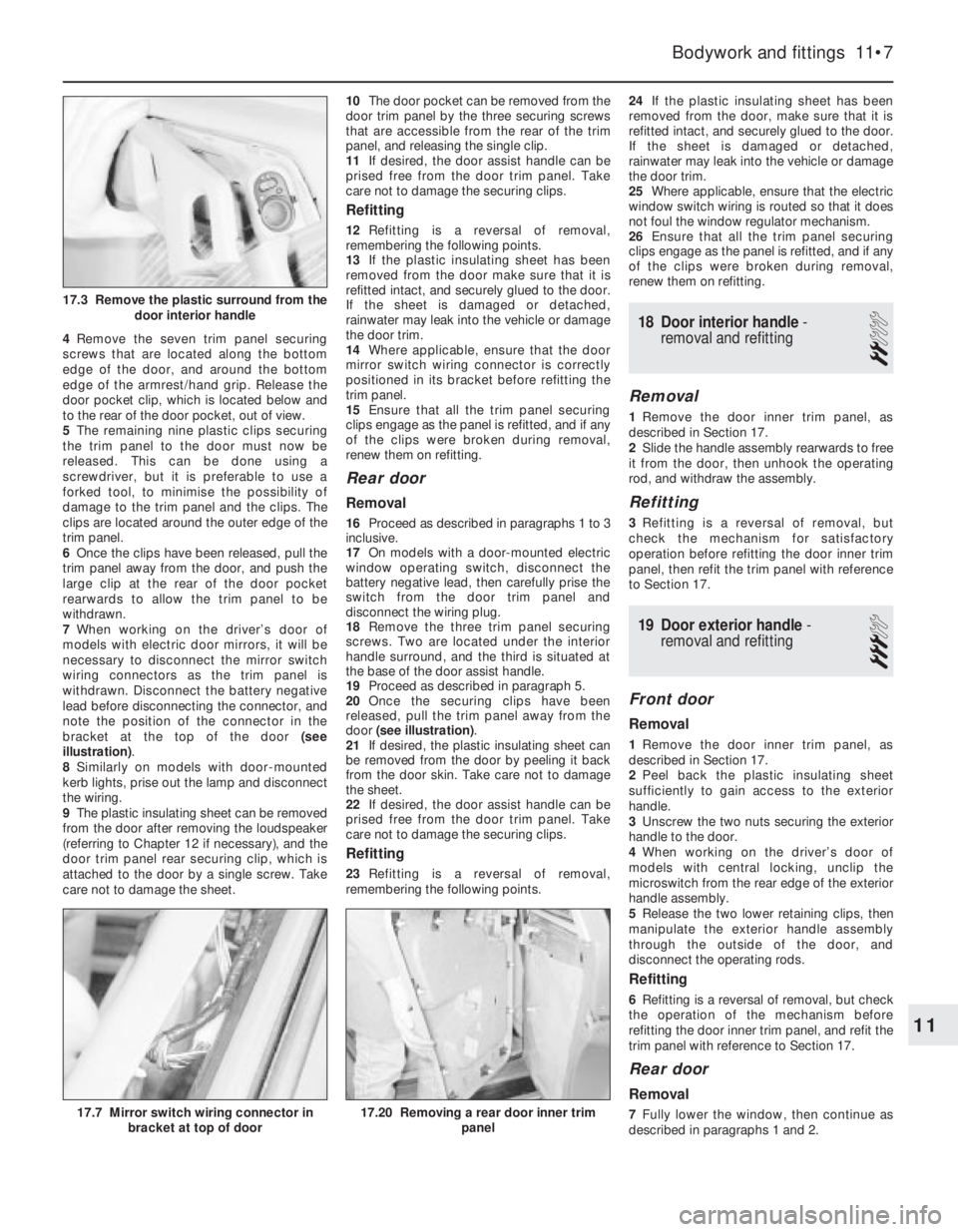
handle (see illustration). Take care not to
damage the door trim panel.
3Prise the plastic surround from the door
interior handle (see illustration).
11•6Bodywork and fittings
15.2 Prising the spring clip from a tailgate
strut balljoint
17.2 Window regulator handle securing
clip16.3 Disconnect the wiring connector
from the front edge of the door
14.1 Tailgate lock cylinder housing - with
central locking (trim panel removed)13.1 Tailgate lock (trim panel removed)
Page 110 of 525
4Remove the seven trim panel securing
screws that are located along the bottom
edge of the door, and around the bottom
edge of the armrest/hand grip. Release the
door pocket clip, which is located below and
to the rear of the door pocket, out of view.
5The remaining nine plastic clips securing
the trim panel to the door must now be
released. This can be done using a
screwdriver, but it is preferable to use a
forked tool, to minimise the possibility of
damage to the trim panel and the clips. The
clips are located around the outer edge of the
trim panel.
6Once the clips have been released, pull the
trim panel away from the door, and push the
large clip at the rear of the door pocket
rearwards to allow the trim panel to be
withdrawn.
7When working on the driver’s door of
models with electric door mirrors, it will be
necessary to disconnect the mirror switch
wiring connectors as the trim panel is
withdrawn. Disconnect the battery negative
lead before disconnecting the connector, and
note the position of the connector in the
bracket at the top of the door (see
illustration).
8Similarly on models with door-mounted
kerb lights, prise out the lamp and disconnect
the wiring.
9The plastic insulating sheet can be removed
from the door after removing the loudspeaker
(referring to Chapter 12 if necessary), and the
door trim panel rear securing clip, which is
attached to the door by a single screw. Take
care not to damage the sheet.10The door pocket can be removed from the
door trim panel by the three securing screws
that are accessible from the rear of the trim
panel, and releasing the single clip.
11If desired, the door assist handle can be
prised free from the door trim panel. Take
care not to damage the securing clips.
Refitting
12Refitting is a reversal of removal,
remembering the following points.
13If the plastic insulating sheet has been
removed from the door make sure that it is
refitted intact, and securely glued to the door.
If the sheet is damaged or detached,
rainwater may leak into the vehicle or damage
the door trim.
14Where applicable, ensure that the door
mirror switch wiring connector is correctly
positioned in its bracket before refitting the
trim panel.
15Ensure that all the trim panel securing
clips engage as the panel is refitted, and if any
of the clips were broken during removal,
renew them on refitting.
Rear door
Removal
16Proceed as described in paragraphs 1 to 3
inclusive.
17On models with a door-mounted electric
window operating switch, disconnect the
battery negative lead, then carefully prise the
switch from the door trim panel and
disconnect the wiring plug.
18Remove the three trim panel securing
screws. Two are located under the interior
handle surround, and the third is situated at
the base of the door assist handle.
19Proceed as described in paragraph 5.
20Once the securing clips have been
released, pull the trim panel away from the
door (see illustration).
21If desired, the plastic insulating sheet can
be removed from the door by peeling it back
from the door skin. Take care not to damage
the sheet.
22If desired, the door assist handle can be
prised free from the door trim panel. Take
care not to damage the securing clips.
Refitting
23Refitting is a reversal of removal,
remembering the following points.24If the plastic insulating sheet has been
removed from the door, make sure that it is
refitted intact, and securely glued to the door.
If the sheet is damaged or detached,
rainwater may leak into the vehicle or damage
the door trim.
25Where applicable, ensure that the electric
window switch wiring is routed so that it does
not foul the window regulator mechanism.
26Ensure that all the trim panel securing
clips engage as the panel is refitted, and if any
of the clips were broken during removal,
renew them on refitting.
18Door interior handle -
removal and refitting
2
Removal
1Remove the door inner trim panel, as
described in Section 17.
2Slide the handle assembly rearwards to free
it from the door, then unhook the operating
rod, and withdraw the assembly.
Refitting
3Refitting is a reversal of removal, but
check the mechanism for satisfactory
operation before refitting the door inner trim
panel, then refit the trim panel with reference
to Section 17.
19Door exterior handle -
removal and refitting
3
Front door
Removal
1Remove the door inner trim panel, as
described in Section 17.
2Peel back the plastic insulating sheet
sufficiently to gain access to the exterior
handle.
3Unscrew the two nuts securing the exterior
handle to the door.
4When working on the driver’s door of
models with central locking, unclip the
microswitch from the rear edge of the exterior
handle assembly.
5Release the two lower retaining clips, then
manipulate the exterior handle assembly
through the outside of the door, and
disconnect the operating rods.
Refitting
6Refitting is a reversal of removal, but check
the operation of the mechanism before
refitting the door inner trim panel, and refit the
trim panel with reference to Section 17.
Rear door
Removal
7Fully lower the window, then continue as
described in paragraphs 1 and 2.
Bodywork and fittings 11•7
17.20 Removing a rear door inner trim
panel17.7 Mirror switch wiring connector in
bracket at top of door
17.3 Remove the plastic surround from the
door interior handle
11
Page 111 of 525
8Pull the weatherstrip from the rear edge of
the window aperture, then unscrew the now
exposed window rear guide rail securing
screw. Note that the screw is of the Torx type.
9Unscrew the remaining window rear guide
rail securing screw (Torx type) which is
accessible through the inner door skin, then
withdraw the guide rail from the door. The
weatherstrip can be left attached to the guide
rail, in which case position the guide rail to
one side out of the way, taking care not to
damage the vehicle paintwork.
10Reach in through the aperture in the rear
of the door, and unclip the plastic shield from
the door lock.
11Unscrew the three Torx type lock securing
bolts from the rear edge of the door, and
lower the lock assembly inside the door.
12Unscrew the two nuts securing the
exterior handle to the door.
13Release the two lower retaining clips, then
manipulate the exterior handle through the
outside of the door, and disconnect the
operating rods.
Refitting
14Refitting is a reversal of removal, but
check the operation of the door lock, handle
and window regulator mechanisms before
refitting the door trim panel, and refit the trim
panel with reference to Section 17.
20Door lock barrel - removal
and refitting
3
Removal
1Remove the door exterior handle, as
described in Section 19.
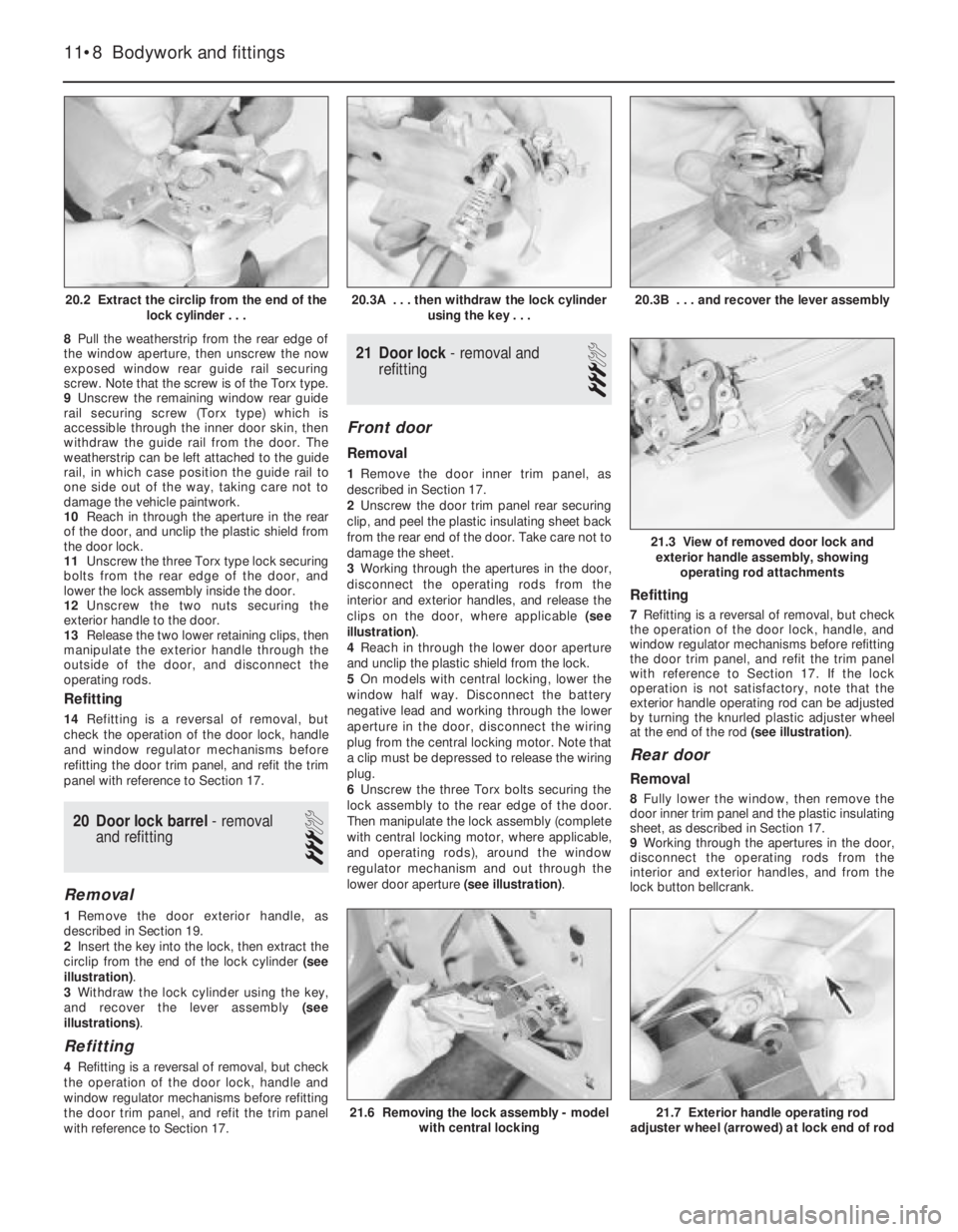
2Insert the key into the lock, then extract the
circlip from the end of the lock cylinder (see
illustration).
3Withdraw the lock cylinder using the key,
and recover the lever assembly (see
illustrations).
Refitting
4 Refitting is a reversal of removal, but check
the operation of the door lock, handle and
window regulator mechanisms before refitting
the door trim panel, and refit the trim panel
with reference to Section 17.
21Door lock -removal and
refitting
3
Front door
Removal
1Remove the door inner trim panel, as
described in Section 17.
2Unscrew the door trim panel rear securing
clip, and peel the plastic insulating sheet back
from the rear end of the door. Take care not to
damage the sheet.
3Working through the apertures in the door,
disconnect the operating rods from the
interior and exterior handles, and release the
clips on the door, where applicable (see
illustration).
4Reach in through the lower door aperture
and unclip the plastic shield from the lock.
5On models with central locking, lower the
window half way. Disconnect the battery
negative lead and working through the lower
aperture in the door, disconnect the wiring
plug from the central locking motor. Note that
a clip must be depressed to release the wiring
plug.
6Unscrew the three Torx bolts securing the
lock assembly to the rear edge of the door.
Then manipulate the lock assembly (complete
with central locking motor, where applicable,
and operating rods), around the window
regulator mechanism and out through the
lower door aperture (see illustration).
Refitting
7Refitting is a reversal of removal, but check
the operation of the door lock, handle, and
window regulator mechanisms before refitting
the door trim panel, and refit the trim panel
with reference to Section 17. If the lock
operation is not satisfactory, note that the
exterior handle operating rod can be adjusted
by turning the knurled plastic adjuster wheel
at the end of the rod (see illustration).
Rear door
Removal
8Fully lower the window, then remove the
door inner trim panel and the plastic insulating
sheet, as described in Section 17.
9Working through the apertures in the door,
disconnect the operating rods from the
interior and exterior handles, and from the
lock button bellcrank.
11•8Bodywork and fittings
20.2 Extract the circlip from the end of the
lock cylinder . . .20.3B . . . and recover the lever assembly
21.7 Exterior handle operating rod
adjuster wheel (arrowed) at lock end of rod21.6 Removing the lock assembly - model
with central locking
21.3 View of removed door lock and
exterior handle assembly, showing
operating rod attachments
20.3A . . . then withdraw the lock cylinder
using the key . . .
Page 112 of 525
10Pull the weatherstrips from the rear edge
of the window aperture, then unscrew the
now-exposed window rear guide rail securing
screw. Note that the screw is of the Torx type.
11Unscrew the remaining window rear guide
rail securing screw (Torx type), which is
accessible through the inner door skin, then
withdraw the guide rail from the door. The
weatherstrip can be left attached to the guide
rail, in which case position the guide rail to
one side out of the way, taking care not to
damage the vehicle paintwork.
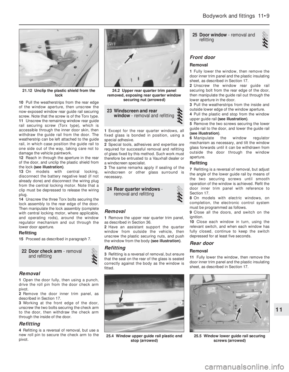
12Reach in through the aperture in the rear
of the door, and unclip the plastic shield from
the lock (see illustration).
13On models with central locking,
disconnect the battery negative lead (if not
already done) and disconnect the wiring plug
from the central locking motor. Note that a
clip must be depressed to release the wiring
plug.
14Unscrew the three Torx bolts securing the
lock assembly to the rear edge of the door.
Then manipulate the lock assembly (complete
with central locking motor, where applicable,
and operating rods), around the window
regulator mechanism and out through the
lower door aperture.
Refitting
15Proceed as described in paragraph 7.
22Door check arm -removal
and refitting
3
Removal
1Open the door fully, then using a punch,
drive the roll pin from the door check arm
pivot.
2Remove the door inner trim panel, as
described in Section 17.
3Working at the front edge of the door,
unscrew the two bolts securing the check arm
to the door, then withdraw the check arm
through the inside of the door.
Refitting
4Refitting is a reversal of removal, but use a
new roll pin to secure the check arm to the
pivot.
23Windscreen and rear
window - removal and refitting
5
1Except for the rear quarter windows, all
fixed glass is bonded in position, using a
special adhesive.
2Special tools, adhesives and expertise are
required for successful removal and refitting
of glass fixed by this method. Such work must
therefore be entrusted to a Vauxhall dealer or
a windscreen specialist.
3The same remarks apply if sealing of the
windscreen or other glass surround is
necessary.
24Rear quarter windows -
removal and refitting
3
Removal
1Remove the upper rear quarter trim panel,
as described in Section 36.
2Have an assistant support the quarter
window from outside the vehicle, then
unscrew the plastic securing nuts, and push
the window from the body (see illustration).
Refitting
3Refitting is a reversal of removal, but ensure
that the seal on the rear of the glass is seated
correctly against the body as the window is
fitted.
25Door window - removal and
refitting
3
Front door
Removal
1Fully lower the window, then remove the
door inner trim panel and the plastic insulating
sheet, as described in Section 17.
2Unscrew the window rear guide rail
securing bolt from the rear edge of the door,
then manipulate the guide rail out through the
lower aperture in the door.
3Pull the weatherstrips from the inside and
outside lower edge of the window aperture.
4Pull the plastic end stop from the window
upper guide rail (see illustration).
5Remove the two screws securing the lower
guide rail to the door, and lower the guide rail
(see illustration).
6Manipulate the window regulator
mechanism as necessary, and tilt the window
glass forwards until it can be withdrawn from
outside the door through the window
aperture.
Refitting
7Refitting is a reversal of removal, but adjust
the angle of the lower guide rail by means of
the two securing screws until smooth
operation of the window is achieved. Refit the
door inner trim panel with reference to
Section 17.
8On models with electric windows, on
completion, the electronic control system
must be programmed as follows.
9Close all the doors, and switch on the
ignition.
10Close each window in turn, using the
relevant switch, and when each window has
fully closed, continue to keep the switch
depressed for at least five seconds.
Rear door
Removal
11Fully lower the window, then remove the
door inner trim panel and the plastic insulating
sheet, as described in Section 17.
Bodywork and fittings 11•9
25.4 Window upper guide rail plastic end
stop (arrowed)25.5 Window lower guide rail securing
screws (arrowed)
24.2 Upper rear quarter trim panel
removed, exposing rear quarter window
securing nut (arrowed)21.12 Unclip the plastic shield from the
lock
11
Page 113 of 525
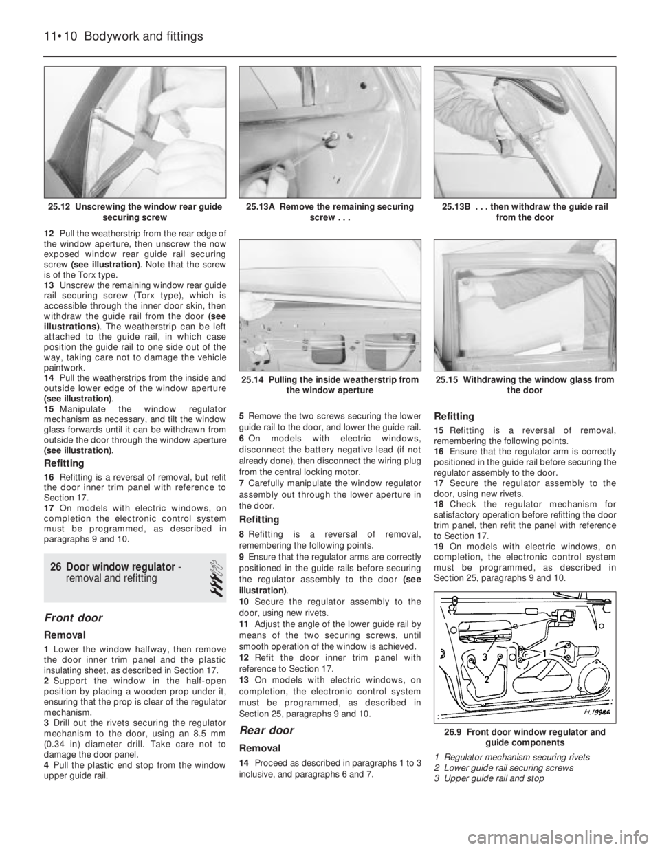
12Pull the weatherstrip from the rear edge of
the window aperture, then unscrew the now
exposed window rear guide rail securing
screw (see illustration). Note that the screw
is of the Torx type.
13Unscrew the remaining window rear guide
rail securing screw (Torx type), which is
accessible through the inner door skin, then
withdraw the guide rail from the door (see
illustrations). The weatherstrip can be left
attached to the guide rail, in which case
position the guide rail to one side out of the
way, taking care not to damage the vehicle
paintwork.
14Pull the weatherstrips from the inside and
outside lower edge of the window aperture
(see illustration).
15Manipulate the window regulator
mechanism as necessary, and tilt the window
glass forwards until it can be withdrawn from
outside the door through the window aperture
(see illustration).
Refitting
16Refitting is a reversal of removal, but refit
the door inner trim panel with reference to
Section 17.
17On models with electric windows, on
completion the electronic control system
must be programmed, as described in
paragraphs 9 and 10.
26Door window regulator -
removal and refitting
3
Front door
Removal
1Lower the window halfway, then remove
the door inner trim panel and the plastic
insulating sheet, as described in Section 17.
2Support the window in the half-open
position by placing a wooden prop under it,
ensuring that the prop is clear of the regulator
mechanism.
3Drill out the rivets securing the regulator
mechanism to the door, using an 8.5 mm
(0.34 in) diameter drill. Take care not to
damage the door panel.
4Pull the plastic end stop from the window
upper guide rail.5Remove the two screws securing the lower
guide rail to the door, and lower the guide rail.
6On models with electric windows,
disconnect the battery negative lead (if not
already done), then disconnect the wiring plug
from the central locking motor.
7Carefully manipulate the window regulator
assembly out through the lower aperture in
the door.
Refitting
8Refitting is a reversal of removal,
remembering the following points.
9Ensure that the regulator arms are correctly
positioned in the guide rails before securing
the regulator assembly to the door (see
illustration).
10Secure the regulator assembly to the
door, using new rivets.
11Adjust the angle of the lower guide rail by
means of the two securing screws, until
smooth operation of the window is achieved.
12Refit the door inner trim panel with
reference to Section 17.
13On models with electric windows, on
completion, the electronic control system
must be programmed, as described in
Section 25, paragraphs 9 and 10.
Rear door
Removal
14Proceed as described in paragraphs 1 to 3
inclusive, and paragraphs 6 and 7.
Refitting
15Refitting is a reversal of removal,
remembering the following points.
16Ensure that the regulator arm is correctly
positioned in the guide rail before securing the
regulator assembly to the door.
17Secure the regulator assembly to the
door, using new rivets.
18Check the regulator mechanism for
satisfactory operation before refitting the door
trim panel, then refit the panel with reference
to Section 17.
19On models with electric windows, on
completion, the electronic control system
must be programmed, as described in
Section 25, paragraphs 9 and 10.
11•10Bodywork and fittings
25.12 Unscrewing the window rear guide
securing screw25.13B . . . then withdraw the guide rail
from the door
26.9 Front door window regulator and
guide components
1 Regulator mechanism securing rivets
2 Lower guide rail securing screws
3 Upper guide rail and stop
25.15 Withdrawing the window glass from
the door25.14 Pulling the inside weatherstrip from
the window aperture
25.13A Remove the remaining securing
screw . . .
Page 122 of 525
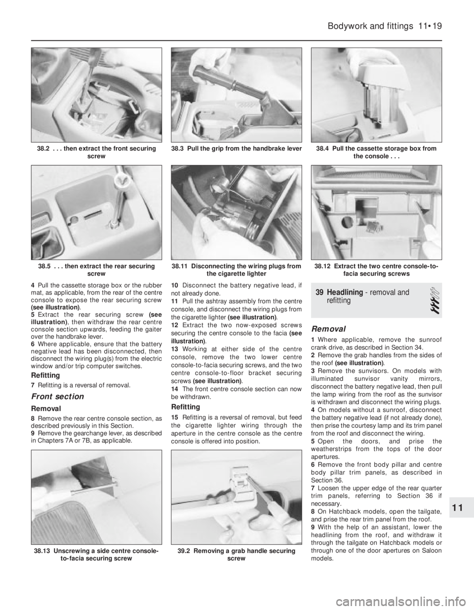
4Pull the cassette storage box or the rubber
mat, as applicable, from the rear of the centre
console to expose the rear securing screw
(see illustration).
5Extract the rear securing screw (see
illustration), then withdraw the rear centre
console section upwards, feeding the gaiter
over the handbrake lever.
6Where applicable, ensure that the battery
negative lead has been disconnected, then
disconnect the wiring plug(s) from the electric
window and/or trip computer switches.
Refitting
7Refitting is a reversal of removal.
Front section
Removal
8Remove the rear centre console section, as
described previously in this Section.
9Remove the gearchange lever, as described
in Chapters 7A or 7B, as applicable. 10Disconnect the battery negative lead, if
not already done.
11Pull the ashtray assembly from the centre
console, and disconnect the wiring plugs from
the cigarette lighter (see illustration).
12Extract the two now-exposed screws
securing the centre console to the facia (see
illustration).
13Working at either side of the centre
console, remove the two lower centre
console-to-facia securing screws, and the two
centre console-to-floor bracket securing
screws (see illustration).
14The front centre console section can now
be withdrawn.
Refitting
15Refitting is a reversal of removal, but feed
the cigarette lighter wiring through the
aperture in the centre console as the centre
console is offered into position.
39Headlining -removal and
refitting
3
Removal
1Where applicable, remove the sunroof
crank drive, as described in Section 34.
2Remove the grab handles from the sides of
the roof (see illustration).
3Remove the sunvisors. On models with
illuminated sunvisor vanity mirrors,
disconnect the battery negative lead, then pull
the lamp wiring from the roof as the sunvisor
is withdrawn and disconnect the wiring plugs.
4On models without a sunroof, disconnect
the battery negative lead (if not already done),
then prise the courtesy lamp and its trim panel
from the roof and disconnect the wiring.
5Open the doors, and prise the
weatherstrips from the tops of the door
apertures.
6Remove the front body pillar and centre
body pillar trim panels, as described in
Section 36.
7Loosen the upper edge of the rear quarter
trim panels, referring to Section 36 if
necessary.
8On Hatchback models, open the tailgate,
and prise the rear trim panel from the roof.
9With the help of an assistant, lower the
headlining from the roof, and withdraw it
through the tailgate on Hatchback models or
through one of the door apertures on Saloon
models.
Bodywork and fittings 11•19
38.4 Pull the cassette storage box from
the console . . .
38.12 Extract the two centre console-to-
facia securing screws38.11 Disconnecting the wiring plugs from
the cigarette lighter
38.3 Pull the grip from the handbrake lever38.2 . . . then extract the front securing
screw
11
38.5 . . . then extract the rear securing
screw
38.13 Unscrewing a side centre console-
to-facia securing screw39.2 Removing a grab handle securing
screw
Page 239 of 525
19Facia ventilation nozzles -
removal and refitting
2
Centre facia ventilation nozzles
Removal
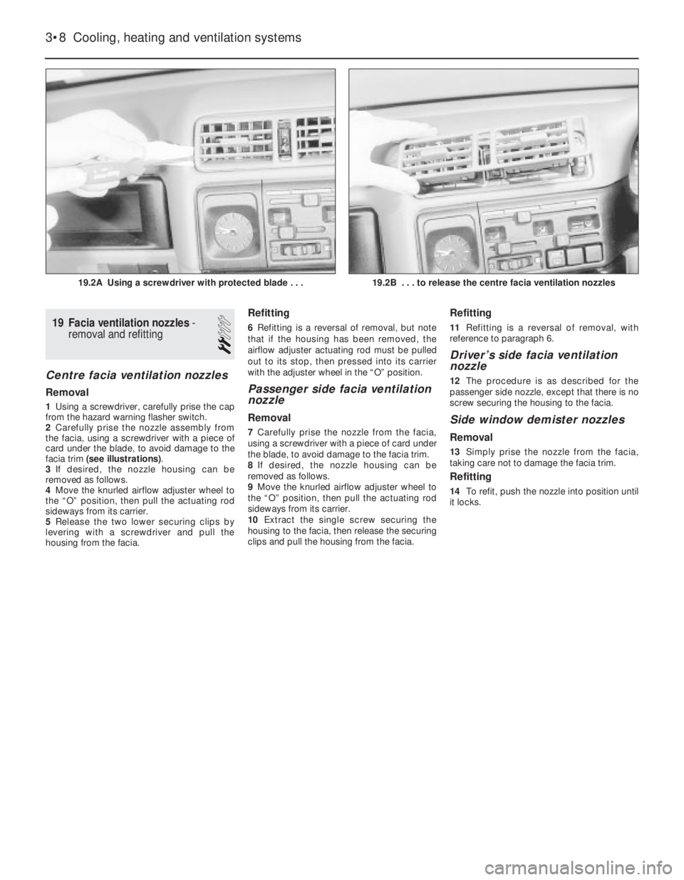
1Using a screwdriver, carefully prise the cap
from the hazard warning flasher switch.
2Carefully prise the nozzle assembly from
the facia, using a screwdriver with a piece of
card under the blade, to avoid damage to the
facia trim (see illustrations).
3If desired, the nozzle housing can be
removed as follows.
4Move the knurled airflow adjuster wheel to
the “O” position, then pull the actuating rod
sideways from its carrier.
5Release the two lower securing clips by
levering with a screwdriver and pull the
housing from the facia.
Refitting
6Refitting is a reversal of removal, but note
that if the housing has been removed, the
airflow adjuster actuating rod must be pulled
out to its stop, then pressed into its carrier
with the adjuster wheel in the “O” position.
Passenger side facia ventilation
nozzle
Removal
7Carefully prise the nozzle from the facia,
using a screwdriver with a piece of card under
the blade, to avoid damage to the facia trim.
8If desired, the nozzle housing can be
removed as follows.
9Move the knurled airflow adjuster wheel to
the “O” position, then pull the actuating rod
sideways from its carrier.
10Extract the single screw securing the
housing to the facia, then release the securing
clips and pull the housing from the facia.
Refitting
11Refitting is a reversal of removal, with
reference to paragraph 6.
Driver’s side facia ventilation
nozzle
12The procedure is as described for the
passenger side nozzle, except that there is no
screw securing the housing to the facia.
Side window demister nozzles
Removal
13Simply prise the nozzle from the facia,
taking care not to damage the facia trim.
Refitting
14To refit, push the nozzle into position until
it locks.
3•8Cooling, heating and ventilation systems
19.2A Using a screwdriver with protected blade . . .19.2B . . . to release the centre facia ventilation nozzles
Page 251 of 525
Engine
m mEngine fails to rotate when attempting to start
m mEngine rotates, but will not start
m mEngine difficult to start when cold
m mEngine difficult to start when hot
m mStarter motor noisy or excessively rough in engagement
m mEngine starts, but stops immediately
m mEngine idles erratically
m mEngine misfires at idle speed
m mEngine misfires throughout the driving speed range
m mEngine hesitates on acceleration
m mEngine stalls
m mEngine lacks power
m mEngine backfires
m mOil pressure warning light illuminated with engine running
m mEngine runs-on after switching off
m mEngine noises
Cooling system
m
mOverheating
m mOvercooling
m mExternal coolant leakage
m mInternal coolant leakage
m mCorrosion
Fuel and exhaust systems
m
mExcessive fuel consumption
m mFuel leakage and/or fuel odour
m mExcessive noise or fumes from exhaust system
Clutch
m
mPedal travels to floor - no pressure or very little resistance
m mClutch fails to disengage (unable to select gears)
m mClutch slips (engine speed increases, with no increase in vehicle
speed)
m mJudder as clutch is engaged
m mNoise when depressing or releasing clutch pedal
Manual transmission
m
mNoisy in neutral with engine running
m mNoisy in one particular gear
m mDifficulty engaging gears
m mJumps out of gear
m mVibration
m mLubricant leaks
Automatic transmission
m
mFluid leakage
m mTransmission fluid brown, or has burned smell
m mGeneral gear selection problems
m mTransmission will not downshift (kickdown) with accelerator fully
depressed
m mEngine will not start in any gear, or starts in gears other than Park
or Neutral
m mTransmission slips, shifts roughly, is noisy, or has no drive in
forward or reverse gears
Driveshafts
m mClicking or knocking noise on turns (at slow speed on full-lock)
m mVibration when accelerating or decelerating
Braking system
m
mVehicle pulls to one side under braking
m mNoise (grinding or high-pitched squeal) when brakes applied
m mExcessive brake pedal travel
m mBrake pedal feels spongy when depressed
m mExcessive brake pedal effort required to stop vehicle
m mJudder felt through brake pedal or steering wheel when braking
m mBrakes binding
m mRear wheels locking under normal braking
Suspension and steering systems
m
mVehicle pulls to one side
m mWheel wobble and vibration
m mExcessive pitching and/or rolling around corners, or during
braking
m mWandering or general instability
m mExcessively stiff steering
m mExcessive play in steering
m mLack of power assistance
m mTyre wear excessive
Electrical system
m
mBattery will not hold a charge for more than a few days
m mIgnition/no-charge warning light remains illuminated with engine
running
m mIgnition/no-charge warning light fails to come on
m mLights inoperative
m mInstrument readings inaccurate or erratic
m mHorn inoperative, or unsatisfactory in operation
m mWindscreen/tailgate wipers inoperative, or unsatisfactory in
operation
m mWindscreen/tailgate washers inoperative, or unsatisfactory in
operation
m mElectric windows inoperative, or unsatisfactory in operation
m mCentral locking system inoperative, or unsatisfactory in operation
The vehicle owner who does his or her own maintenance according to
the recommended service schedules should not have to use this section
of the manual very often. Modern component reliability is such that,
provided those items subject to wear or deterioration are inspected or
renewed at the specified intervals, sudden failure is comparatively rare.
Faults do not usually just happen as a result of sudden failure, but
develop over a period of time. Major mechanical failures in particular are
usually preceded by characteristic symptoms over hundreds or even
thousands of miles. Those components that do occasionally fail without
warning are often small and easily carried in the vehicle.
With any fault-finding, the first step is to decide where to begininvestigations. Sometimes this is obvious, but on other occasions, a
little detective work will be necessary. The owner who makes half a
dozen haphazard adjustments or replacements may be successful in
curing a fault (or its symptoms). However, will be none the wiser if the
fault recurs, and ultimately may have spent more time and money than
was necessary. A calm and logical approach will be found to be more
satisfactory in the long run. Always take into account any warning
signs or abnormalities that may have been noticed in the period
preceding the fault - power loss, high or low gauge readings, unusual
smells, etc. - and remember that failure of components such as fuses
or spark plugs may only be pointers to some underlying fault.
REF•12Fault Finding
Introduction