1988 OPEL CALIBRA lug pattern
[x] Cancel search: lug patternPage 167 of 525

23Disconnect the wiring harness housing
from the fuel injectors, and move it to one
side, taking care not to strain the wiring. Pull
up on the wiring harness housing, and
compress the wiring plug retaining clips to
release the housing from the injectors.
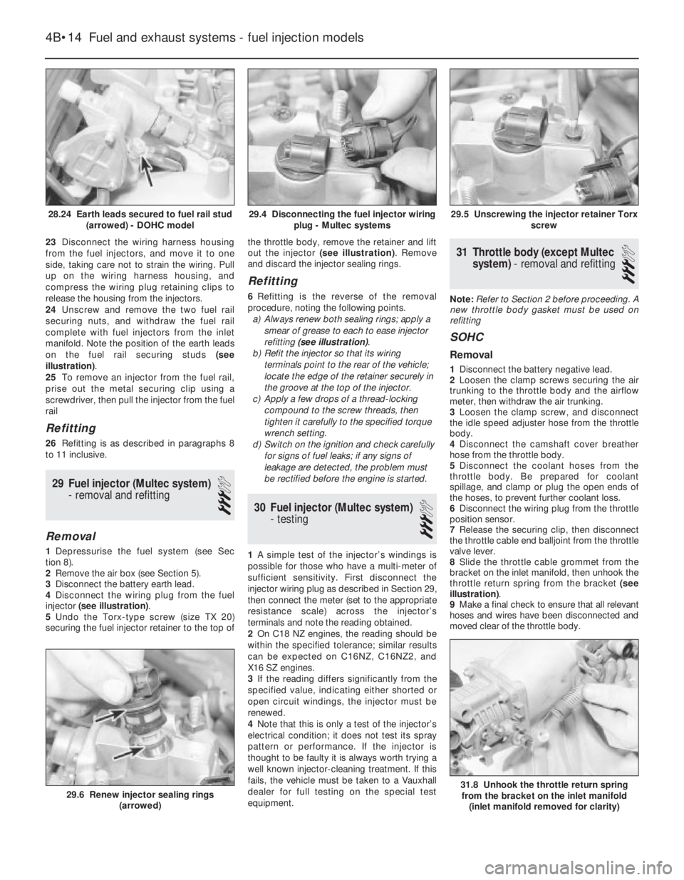
24Unscrew and remove the two fuel rail
securing nuts, and withdraw the fuel rail
complete with fuel injectors from the inlet
manifold. Note the position of the earth leads
on the fuel rail securing studs (see
illustration).
25To remove an injector from the fuel rail,
prise out the metal securing clip using a
screwdriver, then pull the injector from the fuel
rail
Refitting
26Refitting is as described in paragraphs 8
to 11 inclusive.
29Fuel injector (Multec system)
- removal and refitting
3
Removal
1Depressurise the fuel system (see Sec
tion 8).
2Remove the air box (see Section 5).
3Disconnect the battery earth lead.
4Disconnect the wiring plug from the fuel
injector (see illustration).
5Undo the Torx-type screw (size TX 20)
securing the fuel injector retainer to the top ofthe throttle body, remove the retainer and lift
out the injector (see illustration). Remove
and discard the injector sealing rings.
Refitting
6Refitting is the reverse of the removal
procedure, noting the following points.
a)Always renew both sealing rings; apply a
smear of grease to each to ease injector
refitting (see illustration).
b)Refit the injector so that its wiring
terminals point to the rear of the vehicle;
locate the edge of the retainer securely in
the groove at the top of the injector.
c)Apply a few drops of a thread-locking
compound to the screw threads, then
tighten it carefully to the specified torque
wrench setting.
d)Switch on the ignition and check carefully
for signs of fuel leaks; if any signs of
leakage are detected, the problem must
be rectified before the engine is started.
30Fuel injector (Multec system)
- testing
3
1A simple test of the injector’s windings is
possible for those who have a multi-meter of
sufficient sensitivity. First disconnect the
injector wiring plug as described in Section 29,
then connect the meter (set to the appropriate
resistance scale) across the injector’s
terminals and note the reading obtained.
2On C18 NZ engines, the reading should be
within the specified tolerance; similar results
can be expected on C16NZ, C16NZ2, and
X16 SZ engines.
3If the reading differs significantly from the
specified value, indicating either shorted or
open circuit windings, the injector must be
renewed.
4Note that this is only a test of the injector’s
electrical condition; it does not test its spray
pattern or performance. If the injector is
thought to be faulty it is always worth trying a
well known injector-cleaning treatment. If this
fails, the vehicle must be taken to a Vauxhall
dealer for full testing on the special test
equipment.
31Throttle body (except Multec
system) - removal and refitting
3
Note:Refer to Section 2 before proceeding. A
new throttle body gasket must be used on
refitting
SOHC
Removal
1Disconnect the battery negative lead.
2Loosen the clamp screws securing the air
trunking to the throttle body and the airflow
meter, then withdraw the air trunking.
3Loosen the clamp screw, and disconnect
the idle speed adjuster hose from the throttle
body.
4Disconnect the camshaft cover breather
hose from the throttle body.
5Disconnect the coolant hoses from the
throttle body. Be prepared for coolant
spillage, and clamp or plug the open ends of
the hoses, to prevent further coolant loss.
6Disconnect the wiring plug from the throttle
position sensor.
7Release the securing clip, then disconnect
the throttle cable end balljoint from the throttle
valve lever.
8Slide the throttle cable grommet from the
bracket on the inlet manifold, then unhook the
throttle return spring from the bracket (see
illustration).
9Make a final check to ensure that all relevant
hoses and wires have been disconnected and
moved clear of the throttle body.
4B•14Fuel and exhaust systems - fuel injection models
28.24 Earth leads secured to fuel rail stud
(arrowed) - DOHC model29.5 Unscrewing the injector retainer Torx
screw
31.8 Unhook the throttle return spring
from the bracket on the inlet manifold
(inlet manifold removed for clarity)29.6 Renew injector sealing rings
(arrowed)
29.4 Disconnecting the fuel injector wiring
plug - Multec systems
Page 217 of 525

supported to one side out of the way, thus
avoiding the need to disconnect the relevant
hoses, pipes and wiring.
5If the cylinder head is to be removed
complete with the manifolds, disconnect all
relevant hoses, pipes and wiring from the inlet
manifold and associated components,
referring to Chapter 4A or 4B. On carburettor
models, disconnect the hot air hose from the
shroud on the exhaust manifold. Loosen the
alternator mountings, with reference to
Chapter 5, then unbolt the upper alternator
mounting from the inlet manifold.
6If the inlet manifold is to be left in the engine
compartment, continue as follows, otherwise
go on to paragraph 15.
7Disconnect the air cleaner trunking from the
air box on the carburettor or throttle body, or
directly from the throttle body (as applicable),
and disconnect the camshaft cover breather
hose that runs to the carburettor or throttle
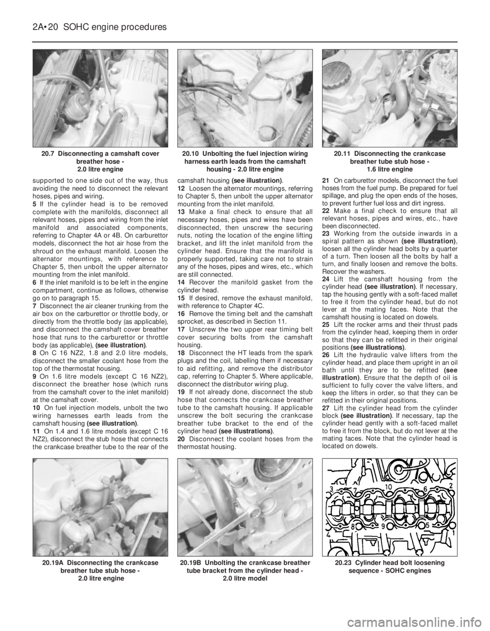
body (as applicable), (see illustration).
8On C 16 NZ2, 1.8 and 2.0 litre models,
disconnect the smaller coolant hose from the
top of the thermostat housing.
9On 1.6 litre models (except C 16 NZ2),
disconnect the breather hose (which runs
from the camshaft cover to the inlet manifold)
at the camshaft cover.
10On fuel injection models, unbolt the two
wiring harnesses earth leads from the
camshaft housing (see illustration).
11On 1.4 and 1.6 litre models (except C 16
NZ2), disconnect the stub hose that connects
the crankcase breather tube to the rear of thecamshaft housing (see illustration).
12Loosen the alternator mountings, referring
to Chapter 5, then unbolt the upper alternator
mounting from the inlet manifold.
13Make a final check to ensure that all
necessary hoses, pipes and wires have been
disconnected, then unscrew the securing
nuts, noting the location of the engine lifting
bracket, and lift the inlet manifold from the
cylinder head. Ensure that the manifold is
properly supported, taking care not to strain
any of the hoses, pipes and wires, etc., which
are still connected.
14Recover the manifold gasket from the
cylinder head.
15If desired, remove the exhaust manifold,
with reference to Chapter 4C.
16Remove the timing belt and the camshaft
sprocket, as described in Section 11.
17Unscrew the two upper rear timing belt
cover securing bolts from the camshaft
housing.
18Disconnect the HT leads from the spark
plugs and the coil, labelling them if necessary
to aid refitting, and remove the distributor
cap, referring to Chapter 5. Where applicable,
disconnect the distributor wiring plug.
19If not already done, disconnect the stub
hose that connects the crankcase breather
tube to the camshaft housing. If applicable
unscrew the bolt securing the crankcase
breather tube bracket to the end of the
cylinder head (see illustrations).
20Disconnect the coolant hoses from the
thermostat housing.21On carburettor models, disconnect the fuel
hoses from the fuel pump. Be prepared for fuel
spillage, and plug the open ends of the hoses,
to prevent further fuel loss and dirt ingress.
22Make a final check to ensure that all
relevant hoses, pipes and wires, etc., have
been disconnected.
23Working from the outside inwards in a
spiral pattern as shown (see illustration),
loosen all the cylinder head bolts by a quarter
of a turn. Then loosen all the bolts by half a
turn, and finally loosen and remove the bolts.
Recover the washers.
24Lift the camshaft housing from the
cylinder head (see illustration). If necessary,
tap the housing gently with a soft-faced mallet
to free it from the cylinder head, but do not
lever at the mating faces. Note that the
camshaft housing is located on dowels.
25Lift the rocker arms and their thrust pads
from the cylinder head, keeping them in order
so that they can be refitted in their original
positions (see illustrations).
26Lift the hydraulic valve lifters from the
cylinder head, and place them upright in an oil
bath until they are to be refitted (see
illustration). Ensure that the depth of oil is
sufficient to fully cover the valve lifters, and
keep the lifters in order, so that they can be
refitted in their original positions.
27Lift the cylinder head from the cylinder
block (see illustration). If necessary, tap the
cylinder head gently with a soft-faced mallet
to free it from the block, but do not lever at the
mating faces. Note that the cylinder head is
located on dowels.
2A•20SOHC engine procedures
20.7 Disconnecting a camshaft cover
breather hose -
2.0 litre engine20.11 Disconnecting the crankcase
breather tube stub hose -
1.6 litre engine
20.23 Cylinder head bolt loosening
sequence - SOHC engines20.19B Unbolting the crankcase breather
tube bracket from the cylinder head -
2.0 litre model20.19A Disconnecting the crankcase
breather tube stub hose -
2.0 litre engine
20.10 Unbolting the fuel injection wiring
harness earth leads from the camshaft
housing - 2.0 litre engine