1988 OPEL CALIBRA washer hose
[x] Cancel search: washer hosePage 27 of 525
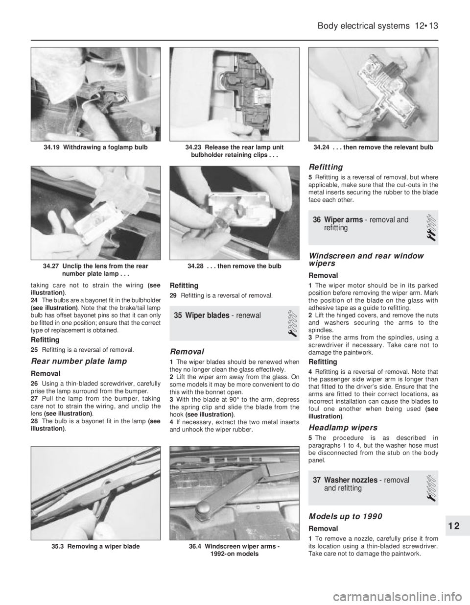
taking care not to strain the wiring (see
illustration).
24The bulbs are a bayonet fit in the bulbholder
(see illustration). Note that the brake/tail lamp
bulb has offset bayonet pins so that it can only
be fitted in one position; ensure that the correct
type of replacement is obtained.
Refitting
25Refitting is a reversal of removal.
Rear number plate lamp
Removal
26Using a thin-bladed screwdriver, carefully
prise the lamp surround from the bumper.
27Pull the lamp from the bumper, taking
care not to strain the wiring, and unclip the
lens (see illustration).
28The bulb is a bayonet fit in the lamp (see
illustration).
Refitting
29Refitting is a reversal of removal.
35Wiper blades -renewal
1
Removal
1The wiper blades should be renewed when
they no longer clean the glass effectively.
2Lift the wiper arm away from the glass. On
some models it may be more convenient to do
this with the bonnet open.
3With the blade at 90°to the arm, depress
the spring clip and slide the blade from the
hook (see illustration).
4If necessary, extract the two metal inserts
and unhook the wiper rubber.
Refitting
5Refitting is a reversal of removal, but where
applicable, make sure that the cut-outs in the
metal inserts securing the rubber to the blade
face each other.
36Wiper arms - removal and
refitting
2
Windscreen and rear window
wipers
Removal
1The wiper motor should be in its parked
position before removing the wiper arm. Mark
the position of the blade on the glass with
adhesive tape as a guide to refitting.
2Lift the hinged covers, and remove the nuts
and washers securing the arms to the
spindles.
3Prise the arms from the spindles, using a
screwdriver if necessary. Take care not to
damage the paintwork.
Refitting
4Refitting is a reversal of removal. Note that
the passenger side wiper arm is longer than
that fitted to the driver’s side. Ensure that the
arms are fitted to their correct locations, as
incorrect installation can cause the blades to
foul one another when being used (see
illustration).
Headlamp wipers
5The procedure is as described in
paragraphs 1 to 4, but the washer hose must
be disconnected from the stub on the body
panel.
37Washer nozzles - removal
and refitting
1
Models up to 1990
Removal
1To remove a nozzle, carefully prise it from
its location using a thin-bladed screwdriver.
Take care not to damage the paintwork.
Body electrical systems 12•13
34.24 . . . then remove the relevant bulb
36.4 Windscreen wiper arms -
1992-on models35.3 Removing a wiper blade
34.28 . . . then remove the bulb34.27 Unclip the lens from the rear
number plate lamp . . .
34.23 Release the rear lamp unit
bulbholder retaining clips . . .34.19 Withdrawing a foglamp bulb
12
Page 28 of 525
2Disconnect the washer hose and withdraw
the nozzle.
Refitting
3To refit, reconnect the washer hose to the
nozzle, and push the nozzle into its locating
hole.
4The nozzles can be adjusted by inserting a
pin into the jet, and swivelling it to the
required position.
1991-on models
5The nozzles on all later models are fitted
with twin jets.
6On some later models, the nozzles are
heated; the circuit is fed through fuse 29 and
is live whenever the ignition is switched on.
Current is regulated by a Positive
Temperature Coefficient (PTC) resistor that
takes outside temperature into account.
38Windscreen wiper motor and
linkage - removal and refitting
3
Removal
1Disconnect the battery negative lead.
2Remove the wiper arms, as described in
Section 36.
3Remove the windscreen cowl panel, as
described in Chapter 11.
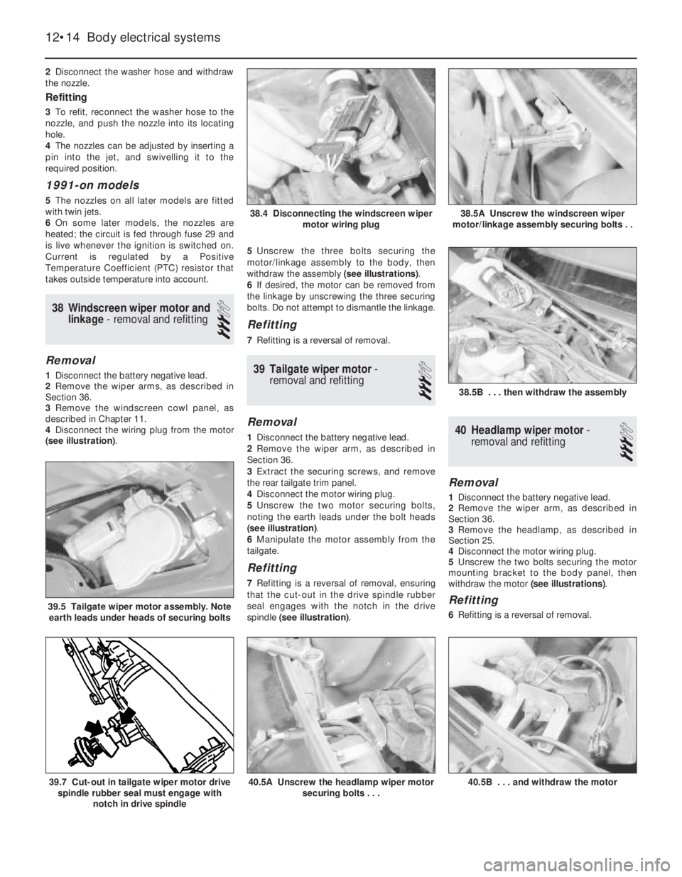
4Disconnect the wiring plug from the motor
(see illustration). 5Unscrew the three bolts securing the
motor/linkage assembly to the body, then
withdraw the assembly (see illustrations).
6If desired, the motor can be removed from
the linkage by unscrewing the three securing
bolts. Do not attempt to dismantle the linkage.
Refitting
7Refitting is a reversal of removal.
39Tailgate wiper motor -
removal and refitting
3
Removal
1Disconnect the battery negative lead.
2Remove the wiper arm, as described in
Section 36.
3Extract the securing screws, and remove
the rear tailgate trim panel.
4Disconnect the motor wiring plug.
5Unscrew the two motor securing bolts,
noting the earth leads under the bolt heads
(see illustration).
6Manipulate the motor assembly from the
tailgate.
Refitting
7Refitting is a reversal of removal, ensuring
that the cut-out in the drive spindle rubber
seal engages with the notch in the drive
spindle (see illustration).
40Headlamp wiper motor -
removal and refitting
3
Removal
1Disconnect the battery negative lead.
2Remove the wiper arm, as described in
Section 36.
3Remove the headlamp, as described in
Section 25.
4Disconnect the motor wiring plug.
5Unscrew the two bolts securing the motor
mounting bracket to the body panel, then
withdraw the motor (see illustrations).
Refitting
6Refitting is a reversal of removal.
12•14Body electrical systems
38.4 Disconnecting the windscreen wiper
motor wiring plug
38.5B . . . then withdraw the assembly
40.5B . . . and withdraw the motor40.5A Unscrew the headlamp wiper motor
securing bolts . . .39.7 Cut-out in tailgate wiper motor drive
spindle rubber seal must engage with
notch in drive spindle
39.5 Tailgate wiper motor assembly. Note
earth leads under heads of securing bolts
38.5A Unscrew the windscreen wiper
motor/linkage assembly securing bolts . .
Page 29 of 525
41Washer fluid reservoir -
removal and refitting
2
1Disconnect the battery negative lead.
Models without headlamp wash
Removal
2Disconnect the wiring from the washer
pump.
3Disconnect the washer fluid hose from the
pump. Be prepared for fluid spillage.
4Remove the screw(s) securing the reservoir
to the body, and withdraw the reservoir.
Refitting
5Refitting is a reversal of removal.
Models with headlamp wash
Removal
6On models with headlamp wash, the
reservoir is in two sections, the upper section,
which can be removed from the engine
compartment, and the lower section, which
must be removed from under the wheel arch.
7Disconnect the wiring from the headlamp
wash non-return valve in the top of the
reservoir.
8Disconnect the washer fluid hoses from the
non-return valve. Be prepared for fluid spillage.
9Remove the screw securing the upper
section of the reservoir to the wing panel.
10Loosen the plastic collar securing the
upper section of the reservoir to the lower
section, then withdraw the upper section of
the reservoir from the engine compartment.
11To remove the lower section of the
reservoir, continue as follows.
12Apply the handbrake, then jack up the
front of the vehicle, and support on axle
stands (see “Jacking and Vehicle Support”)
positioned under the body side members.
13Remove the securing screws, and
withdraw the plastic cover from thebumper/front wing to expose the lower
section of the reservoir.
14Remove the horns, (Section 22).
15Remove the wheel arch liner, (Chapter 11).
16Disconnect the wiring and the fluid hoses
from the washer pump. Be prepared for fluid
spillage.
17Unscrew the bolts securing the
horn/reservoir support bracket and the
reservoir to the body, then withdraw the
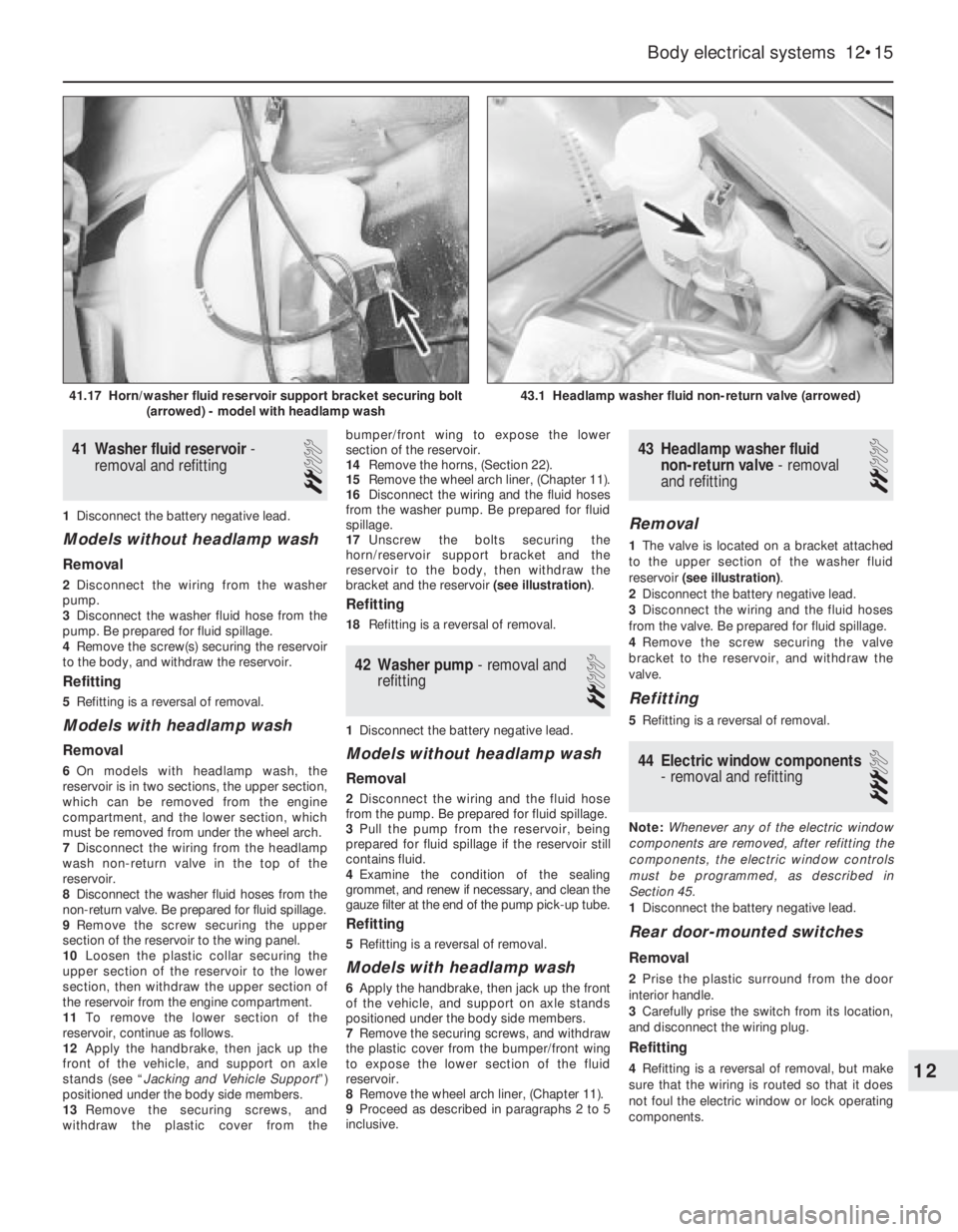
bracket and the reservoir (see illustration).
Refitting
18Refitting is a reversal of removal.
42Washer pump -removal and
refitting
2
1Disconnect the battery negative lead.
Models without headlamp wash
Removal
2Disconnect the wiring and the fluid hose
from the pump. Be prepared for fluid spillage.
3Pull the pump from the reservoir, being
prepared for fluid spillage if the reservoir still
contains fluid.
4Examine the condition of the sealing
grommet, and renew if necessary, and clean the
gauze filter at the end of the pump pick-up tube.
Refitting
5Refitting is a reversal of removal.
Models with headlamp wash
6Apply the handbrake, then jack up the front
of the vehicle, and support on axle stands
positioned under the body side members.
7Remove the securing screws, and withdraw
the plastic cover from the bumper/front wing
to expose the lower section of the fluid
reservoir.
8Remove the wheel arch liner, (Chapter 11).
9Proceed as described in paragraphs 2 to 5
inclusive.
43Headlamp washer fluid
non-return valve -removal
and refitting
2
Removal
1The valve is located on a bracket attached
to the upper section of the washer fluid
reservoir (see illustration).
2Disconnect the battery negative lead.
3Disconnect the wiring and the fluid hoses
from the valve. Be prepared for fluid spillage.
4Remove the screw securing the valve
bracket to the reservoir, and withdraw the
valve.
Refitting
5Refitting is a reversal of removal.
44Electric window components
- removal and refitting
3
Note: Whenever any of the electric window
components are removed, after refitting the
components, the electric window controls
must be programmed, as described in
Section 45.
1Disconnect the battery negative lead.
Rear door-mounted switches
Removal
2Prise the plastic surround from the door
interior handle.
3Carefully prise the switch from its location,
and disconnect the wiring plug.
Refitting
4Refitting is a reversal of removal, but make
sure that the wiring is routed so that it does
not foul the electric window or lock operating
components.
Body electrical systems 12•15
43.1 Headlamp washer fluid non-return valve (arrowed)41.17 Horn/washer fluid reservoir support bracket securing bolt
(arrowed) - model with headlamp wash
12
Page 100 of 525
Inspection
17Examine the distributor cap and rotor arm,
as described in paragraphs 6 and 7. Examine
the O-rings at the rear of the distributor body,
and on the rear of the shaft, and renew if
necessary.
Reassembly
18Reassembly is a reversal of dismantling,
ensuring that the thrustwashers are correctly
located. Note that the drive collar should be
refitted so that the drive peg on the collar is
aligned with the groove in the top of the
distributor shaft (it is possible to fit the drive
collar 180°out of position).
19Refit the distributor as described in
Section 18, and then check and if necessary
adjust the ignition timing, as described in
Section 21.
DOHC models (where
applicable)
20The distributor cap and rotor arm can be
examined as described in paragraphs 6 and 7.
21Ignition timing -checking and
adjustment
4
Note: Refer to Section 3 before proceeding. A
tachometer and a timing light will be required
during this procedure. For details of ignition
timing adjustment required to operate vehicles
on unleaded petrol, refer to Section 22.
14 NV and 16 SV models
Checking
1Start the engine and run it until it reaches
normal operating temperature, then switch
off.
2On 14 NV models, disconnect the vacuum
pipe from the distributor vacuum diaphragm
unit.
3On all models use a spanner applied to the
crankshaft pulley bolt to rotate the crankshaft
clockwise until the notch in the pulley’s
inboard rim aligns with the pointer protruding
from the oil pump housing. On 14 NV models,
where two notches (indicating 10°and 5°
BTDC respectively) are found, rotate the
crankshaft until the second notch (in thedirection of rotation -i.e. 5°BTDC) aligns. Use
white paint or similar to emphasise the pointer
and notch, to make them easier to see.
4Connect a timing light to No 1 cylinder
(nearest the timing belt end of the engine) HT
lead, also a tachometer; follow the equipment
manufacturer’s instructions for connection.
5Start the engine and allow it to idle -the
speed should be between 700 and 1000 rpm.
6On 14 NV models, aim the timing light at the
pointer and check that it is aligned with the
crankshaft pulley notch.
7On early 16 SV models, disconnect the
ignition timing basic adjustment coding plug.
This can be identified by a length of Black
wire joining Brown/Red and Brown/Yellow
wires in a connector plug clipped to the wiring
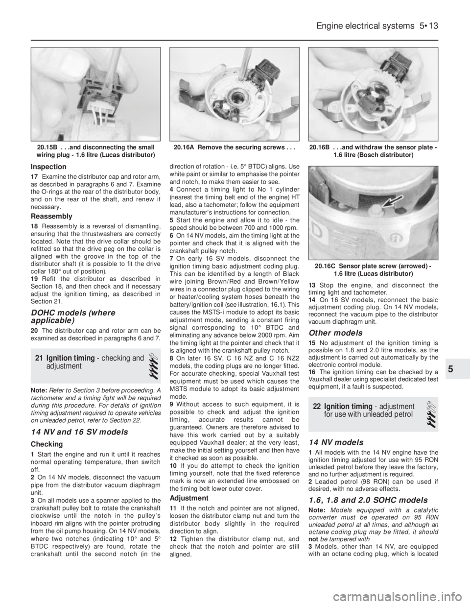
or heater/cooling system hoses beneath the
battery/ignition coil (see illustration, 16.1). This
causes the MSTS-i module to adopt its basic
adjustment mode, sending a constant firing
signal corresponding to 10°BTDC and
eliminating any advance below 2000 rpm. Aim
the timing light at the pointer and check that it
is aligned with the crankshaft pulley notch.
8On later 16 SV, C 16 NZ and C 16 NZ2
models, the coding plugs are no longer fitted.
For accurate checking, special Vauxhall test
equipment must be used which causes the
MSTS module to adopt its basic adjustment
mode.
9Without access to such equipment, it is
possible to check and adjust the ignition
timing, accurate results cannot be
guaranteed. Owners are therefore advised to
have this work carried out by a suitably
equipped Vauxhall dealer; at the very least,
make the initial setting yourself and then have
it checked as soon as possible.
10If you do attempt to check the ignition
timing yourself, note that the fixed reference
mark is now an extended line embossed on
the timing belt lower outer cover.
Adjustment
11If the notch and pointer are not aligned,
loosen the distributor clamp nut and turn the
distributor body slightly in the required
direction to align.
12Tighten the distributor clamp nut, and
check that the notch and pointer are still
aligned. 13Stop the engine, and disconnect the
timing light and tachometer.
14On 16 SV models, reconnect the basic
adjustment coding plug. On 14 NV models,
reconnect the vacuum pipe to the distributor
vacuum diaphragm unit.
Other models
15No adjustment of the ignition timing is
possible on 1.8 and 2.0 litre models, as the
adjustment is carried out automatically by the
electronic control module.
16The ignition timing can be checked by a
Vauxhall dealer using specialist dedicated test
equipment, if a fault is suspected.
22Ignition timing -adjustment
for use with unleaded petrol
3
14 NV models
1All models with the 14 NV engine have the
ignition timing adjusted for use with 95 RON
unleaded petrol before they leave the factory,
and no further adjustment is required.
2Leaded petrol (98 RON) can be used if
desired, with no adverse effects.
1.6, 1.8 and 2.0 SOHC models
Note: Models equipped with a catalytic
converter must be operated on 95 R0N
unleaded petrol at all times, and although an
octane coding plug may be fitted, it should
not be tampered with
3Models, other than 14 NV, are equipped
with an octane coding plug, which is located
Engine electrical systems 5•13
20.16B . . .and withdraw the sensor plate -
1.6 litre (Bosch distributor)
20.16C Sensor plate screw (arrowed) -
1.6 litre (Lucas distributor)
20.16A Remove the securing screws . . .20.15B . . .and disconnecting the small
wiring plug - 1.6 litre (Lucas distributor)
5
Page 107 of 525
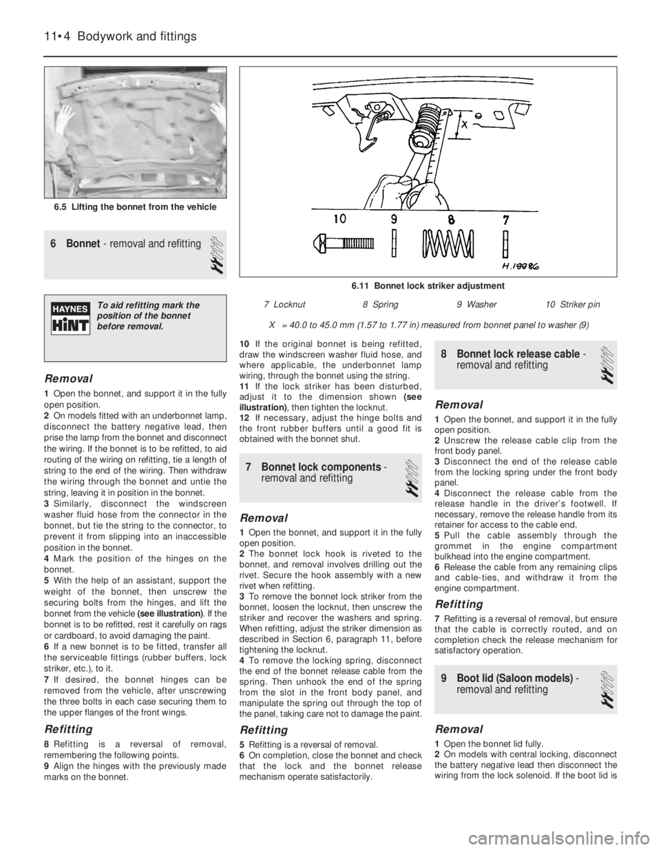
6Bonnet - removal and refitting
2
Removal
1Open the bonnet, and support it in the fully
open position.
2On models fitted with an underbonnet lamp,
disconnect the battery negative lead, then
prise the lamp from the bonnet and disconnect
the wiring. If the bonnet is to be refitted, to aid
routing of the wiring on refitting, tie a length of
string to the end of the wiring. Then withdraw
the wiring through the bonnet and untie the
string, leaving it in position in the bonnet.
3Similarly, disconnect the windscreen
washer fluid hose from the connector in the
bonnet, but tie the string to the connector, to
prevent it from slipping into an inaccessible
position in the bonnet.
4Mark the position of the hinges on the
bonnet.
5With the help of an assistant, support the
weight of the bonnet, then unscrew the
securing bolts from the hinges, and lift the
bonnet from the vehicle (see illustration). If the
bonnet is to be refitted, rest it carefully on rags
or cardboard, to avoid damaging the paint.
6If a new bonnet is to be fitted, transfer all
the serviceable fittings (rubber buffers, lock
striker, etc.), to it.
7If desired, the bonnet hinges can be
removed from the vehicle, after unscrewing
the three bolts in each case securing them to
the upper flanges of the front wings.
Refitting
8Refitting is a reversal of removal,
remembering the following points.
9Align the hinges with the previously made
marks on the bonnet.10If the original bonnet is being refitted,
draw the windscreen washer fluid hose, and
where applicable, the underbonnet lamp
wiring, through the bonnet using the string.
11If the lock striker has been disturbed,
adjust it to the dimension shown (see
illustration), then tighten the locknut.
12If necessary, adjust the hinge bolts and
the front rubber buffers until a good fit is
obtained with the bonnet shut.
7Bonnet lock components -
removal and refitting
2
Removal
1Open the bonnet, and support it in the fully
open position.
2The bonnet lock hook is riveted to the
bonnet, and removal involves drilling out the
rivet. Secure the hook assembly with a new
rivet when refitting.
3To remove the bonnet lock striker from the
bonnet, loosen the locknut, then unscrew the
striker and recover the washers and spring.
When refitting, adjust the striker dimension as
described in Section 6, paragraph 11, before
tightening the locknut.
4To remove the locking spring, disconnect
the end of the bonnet release cable from the
spring. Then unhook the end of the spring
from the slot in the front body panel, and
manipulate the spring out through the top of
the panel, taking care not to damage the paint.
Refitting
5Refitting is a reversal of removal.
6On completion, close the bonnet and check
that the lock and the bonnet release
mechanism operate satisfactorily.
8Bonnet lock release cable -
removal and refitting
2
Removal
1Open the bonnet, and support it in the fully
open position.
2Unscrew the release cable clip from the
front body panel.
3Disconnect the end of the release cable
from the locking spring under the front body
panel.
4Disconnect the release cable from the
release handle in the driver’s footwell. If
necessary, remove the release handle from its
retainer for access to the cable end.
5Pull the cable assembly through the
grommet in the engine compartment
bulkhead into the engine compartment.
6Release the cable from any remaining clips
and cable-ties, and withdraw it from the
engine compartment.
Refitting
7Refitting is a reversal of removal, but ensure
that the cable is correctly routed, and on
completion check the release mechanism for
satisfactory operation.
9Boot lid (Saloon models) -
removal and refitting
2
Removal
1Open the bonnet lid fully.
2On models with central locking, disconnect
the battery negative lead then disconnect the
wiring from the lock solenoid. If the boot lid is
11•4Bodywork and fittings
6.5 Lifting the bonnet from the vehicle
6.11 Bonnet lock striker adjustment
X = 40.0 to 45.0 mm (1.57 to 1.77 in) measured from bonnet panel to washer (9)
7 Locknut8 Spring9 Washer10 Striker pinTo aid refitting mark the
position of the bonnet
before removal.
Page 108 of 525
to be refitted, tie a length of string to the end
of the wiring. Then feed the wiring through the
boot lid and untie the string, leaving it in
position in the boot lid to assist refitting.
3Mark the position of the hinges on the boot
lid.
4With the help of an assistant, support the
weight of the boot lid, then unscrew the
securing bolts from the hinges, and lift the
boot lid from the vehicle. If the boot lid is to be
refitted, rest it carefully on rags or cardboard,
to avoid damaging the paint.
5If a new boot lid is to be fitted, transfer all
the serviceable fittings (rubber buffers, lock
mechanism, etc.), to it.
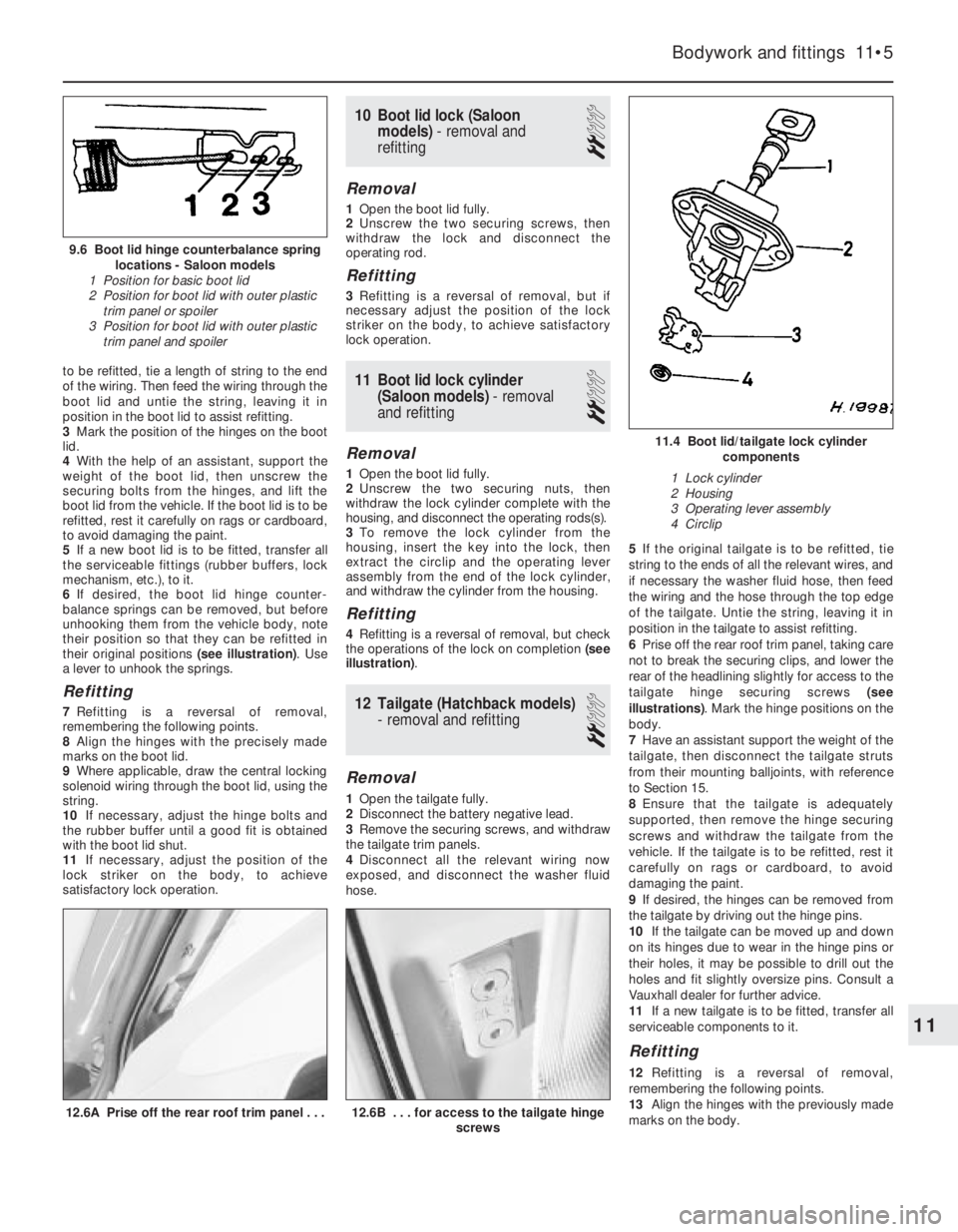
6If desired, the boot lid hinge counter-
balance springs can be removed, but before
unhooking them from the vehicle body, note
their position so that they can be refitted in
their original positions (see illustration). Use
a lever to unhook the springs.
Refitting
7Refitting is a reversal of removal,
remembering the following points.
8Align the hinges with the precisely made
marks on the boot lid.
9Where applicable, draw the central locking
solenoid wiring through the boot lid, using the
string.
10If necessary, adjust the hinge bolts and
the rubber buffer until a good fit is obtained
with the boot lid shut.
11If necessary, adjust the position of the
lock striker on the body, to achieve
satisfactory lock operation.
10Boot lid lock (Saloon
models) - removal and
refitting
2
Removal
1Open the boot lid fully.
2Unscrew the two securing screws, then
withdraw the lock and disconnect the
operating rod.
Refitting
3Refitting is a reversal of removal, but if
necessary adjust the position of the lock
striker on the body, to achieve satisfactory
lock operation.
11Boot lid lock cylinder
(Saloon models) - removal
and refitting
2
Removal
1Open the boot lid fully.
2Unscrew the two securing nuts, then
withdraw the lock cylinder complete with the
housing, and disconnect the operating rods(s).
3To remove the lock cylinder from the
housing, insert the key into the lock, then
extract the circlip and the operating lever
assembly from the end of the lock cylinder,
and withdraw the cylinder from the housing.
Refitting
4Refitting is a reversal of removal, but check
the operations of the lock on completion (see
illustration).
12Tailgate (Hatchback models)
-removal and refitting
2
Removal
1Open the tailgate fully.
2Disconnect the battery negative lead.
3Remove the securing screws, and withdraw
the tailgate trim panels.
4Disconnect all the relevant wiring now
exposed, and disconnect the washer fluid
hose.5If the original tailgate is to be refitted, tie
string to the ends of all the relevant wires, and
if necessary the washer fluid hose, then feed
the wiring and the hose through the top edge
of the tailgate. Untie the string, leaving it in
position in the tailgate to assist refitting.
6Prise off the rear roof trim panel, taking care
not to break the securing clips, and lower the
rear of the headlining slightly for access to the
tailgate hinge securing screws (see
illustrations). Mark the hinge positions on the
body.
7Have an assistant support the weight of the
tailgate, then disconnect the tailgate struts
from their mounting balljoints, with reference
to Section 15.
8Ensure that the tailgate is adequately
supported, then remove the hinge securing
screws and withdraw the tailgate from the
vehicle. If the tailgate is to be refitted, rest it
carefully on rags or cardboard, to avoid
damaging the paint.
9If desired, the hinges can be removed from
the tailgate by driving out the hinge pins.
10If the tailgate can be moved up and down
on its hinges due to wear in the hinge pins or
their holes, it may be possible to drill out the
holes and fit slightly oversize pins. Consult a
Vauxhall dealer for further advice.
11If a new tailgate is to be fitted, transfer all
serviceable components to it.
Refitting
12Refitting is a reversal of removal,
remembering the following points.
13Align the hinges with the previously made
marks on the body.
Bodywork and fittings 11•5
12.6B . . . for access to the tailgate hinge
screws12.6A Prise off the rear roof trim panel . . .
11.4 Boot lid/tailgate lock cylinder
components
1 Lock cylinder
2 Housing
3 Operating lever assembly
4 Circlip
9.6 Boot lid hinge counterbalance spring
locations - Saloon models
1 Position for basic boot lid
2 Position for boot lid with outer plastic
trim panel or spoiler
3 Position for boot lid with outer plastic
trim panel and spoiler
11
Page 109 of 525
14If the original tailgate is being refitted,
draw the wiring and washer fluid hose (where
applicable) through the tailgate, using the
string.
15If necessary, adjust the hinge bolts and
the rubber buffers, to obtain a good fit when
the tailgate is shut.
16If necessary, adjust the position of the
lock striker on the body, to achieve
satisfactory lock operation.
13Tailgate lock (Hatchback
models) - removal and
refitting
2
Proceed as described in Section 10, but
note that for access to the lock, the rear
tailgate trim panel must be removed, after
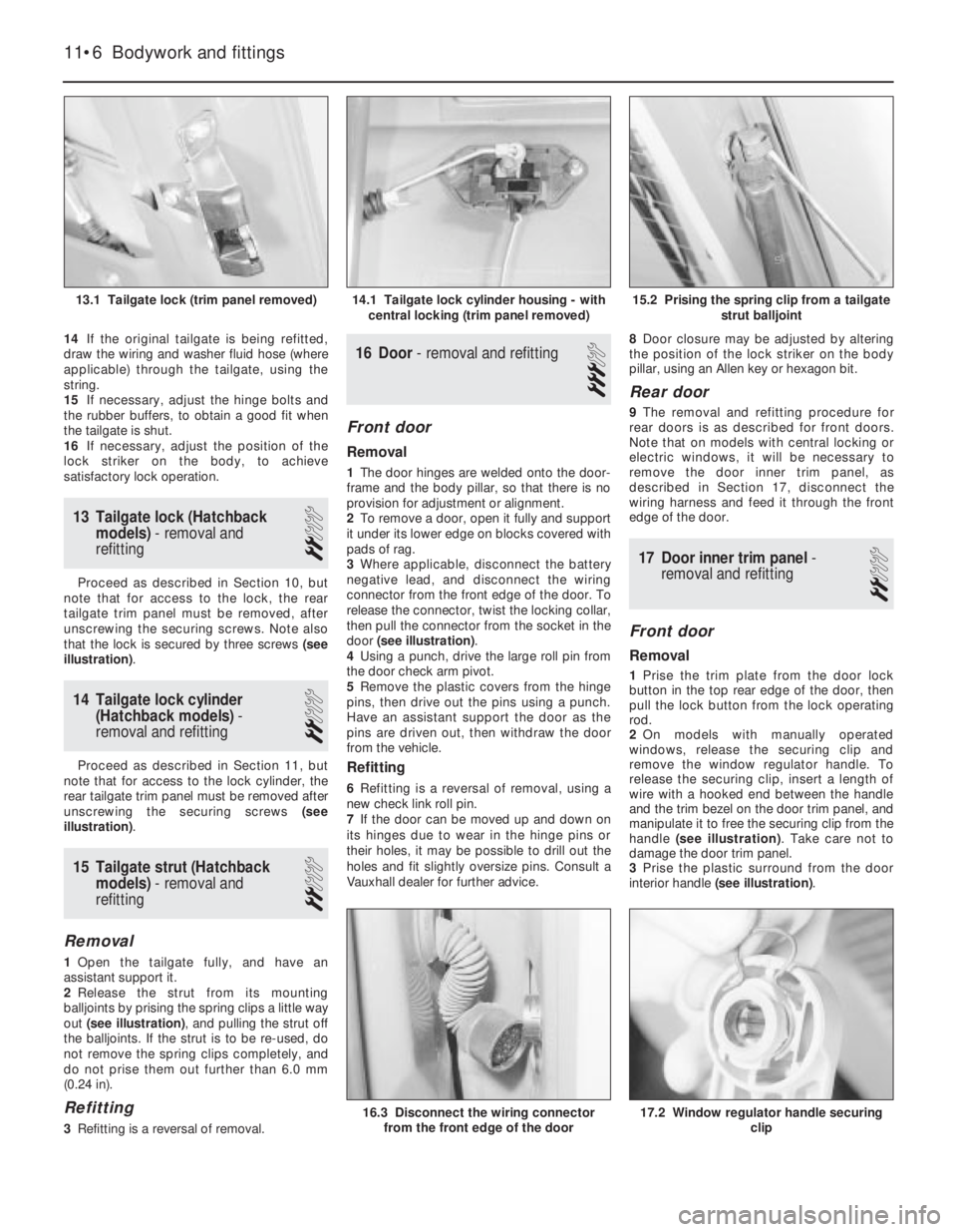
unscrewing the securing screws. Note also
that the lock is secured by three screws (see
illustration).
14Tailgate lock cylinder
(Hatchback models) -
removal and refitting
2
Proceed as described in Section 11, but
note that for access to the lock cylinder, the
rear tailgate trim panel must be removed after
unscrewing the securing screws (see
illustration).
15Tailgate strut (Hatchback
models) - removal and
refitting
2
Removal
1Open the tailgate fully, and have an
assistant support it.
2Release the strut from its mounting
balljoints by prising the spring clips a little way
out (see illustration), and pulling the strut off
the balljoints. If the strut is to be re-used, do
not remove the spring clips completely, and
do not prise them out further than 6.0 mm
(0.24 in).
Refitting
3Refitting is a reversal of removal.
16Door - removal and refitting
3
Front door
Removal
1The door hinges are welded onto the door-
frame and the body pillar, so that there is no
provision for adjustment or alignment.
2To remove a door, open it fully and support
it under its lower edge on blocks covered with
pads of rag.
3Where applicable, disconnect the battery
negative lead, and disconnect the wiring
connector from the front edge of the door. To
release the connector, twist the locking collar,
then pull the connector from the socket in the
door (see illustration).
4Using a punch, drive the large roll pin from
the door check arm pivot.
5Remove the plastic covers from the hinge
pins, then drive out the pins using a punch.
Have an assistant support the door as the
pins are driven out, then withdraw the door
from the vehicle.
Refitting
6Refitting is a reversal of removal, using a
new check link roll pin.
7If the door can be moved up and down on
its hinges due to wear in the hinge pins or
their holes, it may be possible to drill out the
holes and fit slightly oversize pins. Consult a
Vauxhall dealer for further advice.8Door closure may be adjusted by altering
the position of the lock striker on the body
pillar, using an Allen key or hexagon bit.
Rear door
9The removal and refitting procedure for
rear doors is as described for front doors.
Note that on models with central locking or
electric windows, it will be necessary to
remove the door inner trim panel, as
described in Section 17, disconnect the
wiring harness and feed it through the front
edge of the door.
17Door inner trim panel -
removal and refitting
2
Front door
Removal
1Prise the trim plate from the door lock
button in the top rear edge of the door, then
pull the lock button from the lock operating
rod.
2On models with manually operated
windows, release the securing clip and
remove the window regulator handle. To
release the securing clip, insert a length of
wire with a hooked end between the handle
and the trim bezel on the door trim panel, and
manipulate it to free the securing clip from the
handle (see illustration). Take care not to
damage the door trim panel.
3Prise the plastic surround from the door
interior handle (see illustration).
11•6Bodywork and fittings
15.2 Prising the spring clip from a tailgate
strut balljoint
17.2 Window regulator handle securing
clip16.3 Disconnect the wiring connector
from the front edge of the door
14.1 Tailgate lock cylinder housing - with
central locking (trim panel removed)13.1 Tailgate lock (trim panel removed)
Page 115 of 525
6Carefully withdraw the bumper from the
vehicle.
Refitting
7Refitting is a reversal of removal.
Rear bumper
Removal
8Remove the rear trim panel from the
luggage compartment by prising up the top
edge to release the clips, then lift the panel
upwards to free it from the lower locating
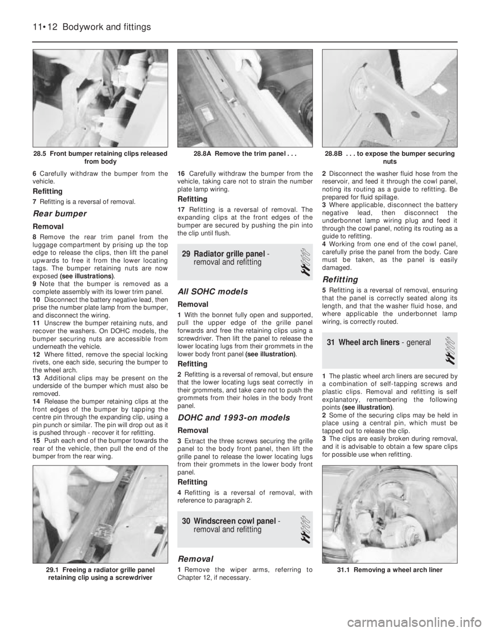
tags. The bumper retaining nuts are now
exposed (see illustrations).
9Note that the bumper is removed as a
complete assembly with its lower trim panel.
10Disconnect the battery negative lead, then
prise the number plate lamp from the bumper,
and disconnect the wiring.
11Unscrew the bumper retaining nuts, and
recover the washers. On DOHC models, the
bumper securing nuts are accessible from
underneath the vehicle.
12Where fitted, remove the special locking
rivets, one each side, securing the bumper to
the wheel arch.
13Additional clips may be present on the
underside of the bumper which must also be
removed.
14Release the bumper retaining clips at the
front edges of the bumper by tapping the
centre pin through the expanding clip, using a
pin punch or similar. The pin will drop out as it
is pushed through - recover it for refitting.
15Push each end of the bumper towards the
rear of the vehicle, then pull the end of the
bumper from the rear wing.16Carefully withdraw the bumper from the
vehicle, taking care not to strain the number
plate lamp wiring.
Refitting
17Refitting is a reversal of removal. The
expanding clips at the front edges of the
bumper are secured by pushing the pin into
the clip until flush.
29Radiator grille panel -
removal and refitting
2
All SOHC models
Removal
1With the bonnet fully open and supported,
pull the upper edge of the grille panel
forwards and free the retaining clips using a
screwdriver. Then lift the panel to release the
lower locating lugs from their grommets in the
lower body front panel (see illustration).
Refitting
2Refitting is a reversal of removal, but ensure
that the lower locating lugs seat correctly in
their grommets, and take care not to push the
grommets from their holes in the body front
panel.
DOHC and 1993-on models
Removal
3Extract the three screws securing the grille
panel to the body front panel, then lift the
grille panel to release the lower locating lugs
from their grommets in the lower body front
panel.
Refitting
4Refitting is a reversal of removal, with
reference to paragraph 2.
30Windscreen cowl panel -
removal and refitting
2
Removal
1Remove the wiper arms, referring to
Chapter 12, if necessary.2Disconnect the washer fluid hose from the
reservoir, and feed it through the cowl panel,
noting its routing as a guide to refitting. Be
prepared for fluid spillage.
3Where applicable, disconnect the battery
negative lead, then disconnect the
underbonnet lamp wiring plug and feed it
through the cowl panel, noting its routing as a
guide to refitting.
4Working from one end of the cowl panel,
carefully prise the panel from the body. Care
must be taken, as the panel is easily
damaged.
Refitting
5Refitting is a reversal of removal, ensuring
that the panel is correctly seated along its
length, and that the washer fluid hose, and
where applicable the underbonnet lamp
wiring, is correctly routed.
31Wheel arch liners - general
2
1The plastic wheel arch liners are secured by
a combination of self-tapping screws and
plastic clips. Removal and refitting is self
explanatory, remembering the following
points (see illustration).
2Some of the securing clips may be held in
place using a central pin, which must be
tapped out to release the clip.
3The clips are easily broken during removal,
and it is advisable to obtain a few spare clips
for possible use when refitting.
11•12Bodywork and fittings
28.8B . . . to expose the bumper securing
nuts
31.1 Removing a wheel arch liner29.1 Freeing a radiator grille panel
retaining clip using a screwdriver
28.8A Remove the trim panel . . .28.5 Front bumper retaining clips released
from body