1988 OPEL CALIBRA washer hose
[x] Cancel search: washer hosePage 209 of 525
9Engine and transmission
mountings - renewal
3
Note: New left and right-hand
engine/transmission mounting-to-body bolts
must be used on refitting
1The engine/transmission assembly is
suspended in the engine compartment on
three mountings, two of which are attached to
the transmission, and one to the engine.
Right-hand mounting
2If not already done, apply the handbrake,
then raise the front of the vehicle, and support
securely on axle stands (see “Jacking and
Vehicle Support”)..
3Attach lifting tackle and a hoist to the
engine lifting brackets on the cylinder head,
and support the weight of the engine.
4Working under the vehicle, unbolt the
engine mounting bracket from the cylinder
block, and unbolt the mounting block from the
body, then withdraw the bracket/mounting
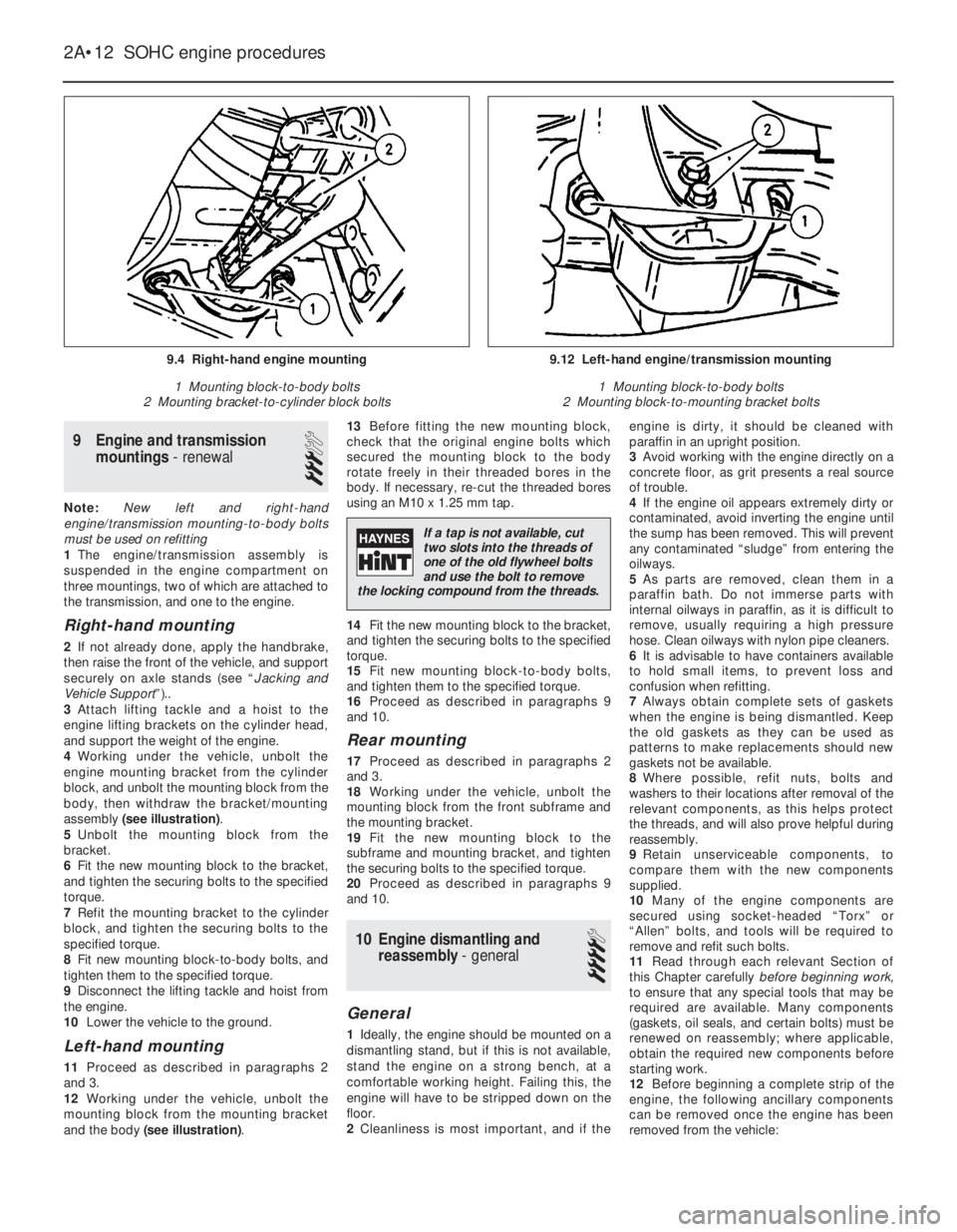
assembly (see illustration).
5Unbolt the mounting block from the
bracket.
6Fit the new mounting block to the bracket,
and tighten the securing bolts to the specified
torque.
7Refit the mounting bracket to the cylinder
block, and tighten the securing bolts to the
specified torque.
8Fit new mounting block-to-body bolts, and
tighten them to the specified torque.
9Disconnect the lifting tackle and hoist from
the engine.
10Lower the vehicle to the ground.
Left-hand mounting
11Proceed as described in paragraphs 2
and 3.
12Working under the vehicle, unbolt the
mounting block from the mounting bracket
and the body (see illustration).13Before fitting the new mounting block,
check that the original engine bolts which
secured the mounting block to the body
rotate freely in their threaded bores in the
body. If necessary, re-cut the threaded bores
using an M10 x 1.25 mm tap.
14Fit the new mounting block to the bracket,
and tighten the securing bolts to the specified
torque.
15Fit new mounting block-to-body bolts,
and tighten them to the specified torque.
16Proceed as described in paragraphs 9
and 10.
Rear mounting
17Proceed as described in paragraphs 2
and 3.
18Working under the vehicle, unbolt the
mounting block from the front subframe and
the mounting bracket.
19Fit the new mounting block to the
subframe and mounting bracket, and tighten
the securing bolts to the specified torque.
20Proceed as described in paragraphs 9
and 10.
10Engine dismantling and
reassembly - general
4
General
1Ideally, the engine should be mounted on a
dismantling stand, but if this is not available,
stand the engine on a strong bench, at a
comfortable working height. Failing this, the
engine will have to be stripped down on the
floor.
2Cleanliness is most important, and if theengine is dirty, it should be cleaned with
paraffin in an upright position.
3Avoid working with the engine directly on a
concrete floor, as grit presents a real source
of trouble.
4If the engine oil appears extremely dirty or
contaminated, avoid inverting the engine until
the sump has been removed. This will prevent
any contaminated “sludge” from entering the
oilways.
5As parts are removed, clean them in a
paraffin bath. Do not immerse parts with
internal oilways in paraffin, as it is difficult to
remove, usually requiring a high pressure
hose. Clean oilways with nylon pipe cleaners.
6It is advisable to have containers available
to hold small items, to prevent loss and
confusion when refitting.
7Always obtain complete sets of gaskets
when the engine is being dismantled. Keep
the old gaskets as they can be used as
patterns to make replacements should new
gaskets not be available.
8Where possible, refit nuts, bolts and
washers to their locations after removal of the
relevant components, as this helps protect
the threads, and will also prove helpful during
reassembly.
9Retain unserviceable components, to
compare them with the new components
supplied.
10Many of the engine components are
secured using socket-headed “Torx” or
“Allen” bolts, and tools will be required to
remove and refit such bolts.
11Read through each relevant Section of
this Chapter carefullybeforebeginning work,
to ensure that any special tools that may be
required are available. Many components
(gaskets, oil seals, and certain bolts) must be
renewed on reassembly; where applicable,
obtain the required new components before
starting work.
12Before beginning a complete strip of the
engine, the following ancillary components
can be removed once the engine has been
removed from the vehicle:
2A•12SOHC engine procedures
9.4 Right-hand engine mounting
1 Mounting block-to-body bolts
2 Mounting bracket-to-cylinder block bolts9.12 Left-hand engine/transmission mounting
1 Mounting block-to-body bolts
2 Mounting block-to-mounting bracket bolts
If a tap is not available, cut
two slots into the threads of
one of the old flywheel bolts
and use the bolt to remove
the locking compound from the threads.
Page 210 of 525
a)Inlet and exhaust manifolds (where
applicable)
b)Starter motor
c)Rear coolant gallery and hoses
d)Oil pressure switch
e)Oil temperature switch (where applicable)
f)Oil level sensor (where applicable)
g)Knock sensor (where applicable)
h)TDC sensor (where applicable)
i)Distributor components
j)Fuel pump (where applicable)
k)Thermostat/housing (N 16 NZ2, 1.8 and
2.0 litre models)
l)Power steering pump and mounting
bracket (where applicable)
m)Alternator mounting bracket
n)Engine lifting brackets
o)Dipstick/crankcase breather tube
p)Inlet manifold mounting bracket (where
applicable)
13To ensure maximum life, with minimum
trouble, from a rebuilt engine, not only must
everything be correctly assembled, but it must
also be spotlessly clean. All oilways and
coolant passages must be clear, and all
washers must be fitted in their original
positions. Oil all bearings and other moving
surfaces thoroughly with clean engine oil
during assembly.
14Before assembly begins, renew any bolts
or studs with damaged threads.
15Obtain a torque wrench, an angle-torque
gauge, sockets and bits, an oil can, clean
lint-free rag, and a set of engine gaskets and
oil seals, together with a new oil filter.16If they have been removed, new cylinder
head bolts, flywheel bolts, big-end bearing
cap bolts and main bearing cap bolts will also
be required.
17On completion of reassembly, refit the
applicable ancillary components listed in
paragraph 12.
18Follow procedure shown in Section 37.
11Timing belt and sprockets
(without automatic tensioner) -
removal, refitting and adjustment
3
Note: A two-legged puller may be required to
remove the crankshaft sprocket on N 16 NZ2,
1.8 and 2.0 litre models.Some of the later 1.4
and 1.6 litre engines, identifiable by the
squared-off top surfaces of the timing belt
covers, are fitted with spring-loaded auto-matic timing belt tensioners to ensure correct
belt tensioning on assembly.
Removal
1Disconnect the battery negative lead.
2On models with power steering, remove the
pump drivebelt, see Chapters 1 and 10.
3Remove the alternator drivebelt, as
described in Chapter 5.
4On C 16 NZ2, 1.8 and 2.0 litre models,
disconnect the wiring from the temperature
gauge sender.
5Release the securing clips (or hexagon-
headed screws, if fitted), and remove the main
outer timing belt cover, then unclip the smaller
outer timing belt cover from the coolant pump.
Where applicable, three screws retain the lower
(small) outer cover to the rear cover, the fourth
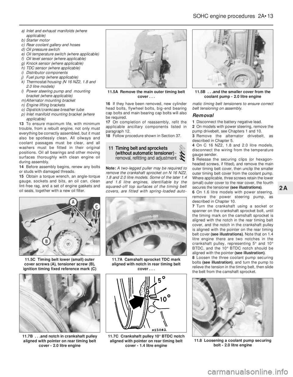
secures the tensioner (see illustrations).
6On 1.6 litre models with power steering,
remove the power steering pump, as
described in Chapter 10.
7Turn the crankshaft using a socket or
spanner on the crankshaft sprocket bolt, until
the timing mark on the camshaft sprocket is
aligned with the notch in the rear timing belt
cover, and the notch in the crankshaft pulley
is aligned with the pointer on the rear timing
belt cover (see illustrations). Note that on 1.4
litre engine there are two notches in the
crankshaft pulley, representing 5°and 10°
BTDC, and the 10°BTDC notch should be
aligned with the pointer (see illustration).
8Loosen the three coolant pump securing
bolts (see illustration), and turn the pump to
relieve the tension in the timing belt, then slide
the belt from the camshaft sprocket.
SOHC engine procedures 2A•13
11.5C Timing belt lower (small) outer
cover screws (A), tensioner screw (B),
ignition timing fixed reference mark (C)
11.8 Loosening a coolant pump securing
bolt - 2.0 litre engine11.7C Crankshaft pulley 10°BTDC notch
aligned with pointer on rear timing belt
cover - 1.4 litre engine11.7B . . .and notch in crankshaft pulley
aligned with pointer on rear timing belt
cover - 2.0 litre engine
11.7A Camshaft sprocket TDC mark
aligned with notch in rear timing belt
cover . . .
11.5B . . .and the smaller cover from the
coolant pump - 2.0 litre engine11.5A Remove the main outer timing belt
cover . . .
2A
Page 211 of 525

9The crankshaft pulley must now be
removed. On 1.4 and 1.6 litre engines (except
C 16 NZ2), the pulley is secured by a single
bolt, which also secures the crankshaft
sprocket. On C 16 NZ2, 1.8 and 2.0 litre
engines, the pulley is secured by four bolts,
which must be unscrewed using an Allen key
or hexagon bit. On manual transmission
models, if the engine is in the vehicle, the
crankshaft can be prevented from turning by
having an assistant engage first gear and
depress the brake pedal. Alternatively, the
flywheel ring gear teeth can be jammed using
a large screwdriver or similar tool.
10With the crankshaft pulley removed, the
timing belt can be withdrawn.
11If desired, the sprockets and the rear
timing belt cover can be removed as follows,
otherwise go on to paragraph 23.
12To remove the camshaft sprocket, firstdisconnect the breather hose(s) from the
camshaft cover, then unscrew the securing
bolts noting the locations of the HT lead
brackets and any other wiring brackets, and
remove the camshaft cover.
13Recover the gasket. Prevent the camshaft
from turning by holding it with a spanner on
the flats provided between No’s 3 and 4
camshaft lobes, and unscrew the camshaft
sprocket bolt.
14Withdraw the sprocket from the end of the
camshaft.
15To remove the crankshaft sprocket on 1.4
and 1.6 litre engines (except C 16 NZ2), if
necessary, remove the lower securing bolts
from the main rear timing belt cover and use
two large screwdrivers behind the cover to
lever off the sprocket. Remove the Woodruff
key if it is loose.
16To remove the crankshaft sprocket on C
16 NZ2, 1.8 and 2.0 litre engines, it will benecessary to prevent the crankshaft from
turning, as described in paragraph 9. Take
care when unscrewing the sprocket bolt, as it
is very tight. If necessary, use a two-legged
puller to remove the sprocket. Recover the
Woodruff key and the thrustwasher from the
end of the crankshaft.
17To remove the main rear timing belt cover
on C 16 NZ2, 1.8 and 2.0 litre models
disconnect the TDC sensor wiring plug and
unclip the wiring from the belt cover. Then
unscrew the two upper securing bolts and the
lower securing bolt(s) (one in the case of C 16
NZ2, 1.8 and 2.0 litre engines, two on other
SOHC engines). Withdraw the cover,
manipulating it from the smaller rear belt
cover on the coolant pump (see illustrations).
18If desired, the smaller rear belt cover can
be removed from the coolant pump, after
unscrewing the securing bolt (see
illustration), by rotating it to disengage it from
the retaining flange on the pump.
Refitting
19Refit the rear timing belt cover(s) using a
reversal of the removal procedure, and
ensuring that the main cover engages correctly
with the smaller cover on the coolant pump.
20On C 16 NZ2, 1.8 and 2.0 litre engines,
refit the thrustwasher and the Woodruff key to
the end of the crankshaft. Then refit the
crankshaft sprocket, and tighten the securing
bolt to the specified torque in the two stages
given in the Specifications. Ensure that the
washer is in place under the bolt head, and
prevent the crankshaft from turning as during
removal (see illustrations).
2A•14SOHC engine procedures
11.17A Loosening the main rear timing
belt cover lower securing bolt -
2.0 litre engine11.18 Unscrewing the coolant pump rear
belt cover securing bolt - 2.0 litre engine
11.20E Tighten the bolt to the specified
torque . . .11.20D . . .and the washer and bolt11.20C . . .the crankshaft sprocket . . .
11.20B . . . the Woodruff key . . .11.20A Refit the thrustwasher . . .
11.17B Main rear timing belt cover lower
securing bolts (arrowed) - 1.6 SV engine
Page 217 of 525
supported to one side out of the way, thus
avoiding the need to disconnect the relevant
hoses, pipes and wiring.
5If the cylinder head is to be removed
complete with the manifolds, disconnect all
relevant hoses, pipes and wiring from the inlet
manifold and associated components,
referring to Chapter 4A or 4B. On carburettor
models, disconnect the hot air hose from the
shroud on the exhaust manifold. Loosen the
alternator mountings, with reference to
Chapter 5, then unbolt the upper alternator
mounting from the inlet manifold.
6If the inlet manifold is to be left in the engine
compartment, continue as follows, otherwise
go on to paragraph 15.
7Disconnect the air cleaner trunking from the
air box on the carburettor or throttle body, or
directly from the throttle body (as applicable),
and disconnect the camshaft cover breather
hose that runs to the carburettor or throttle
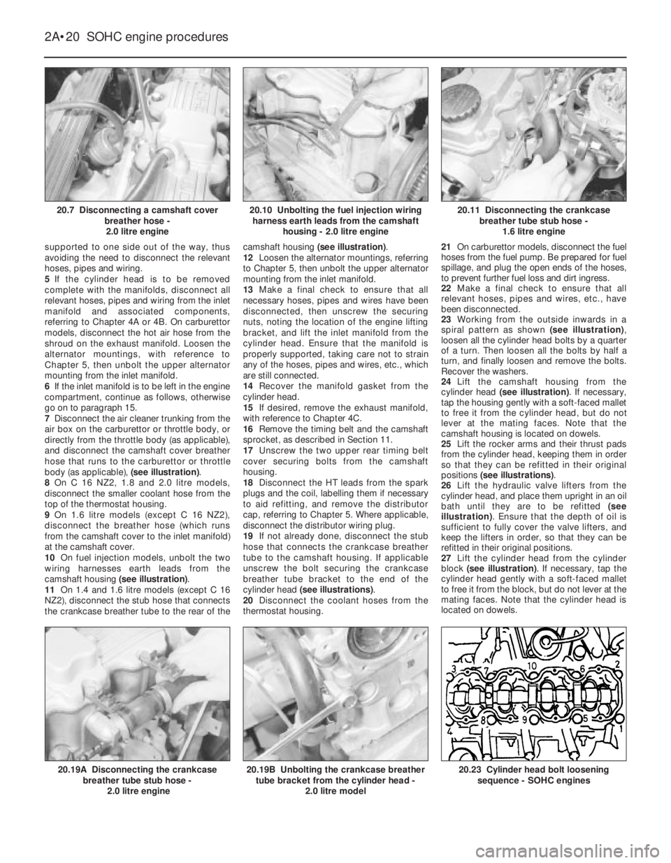
body (as applicable), (see illustration).
8On C 16 NZ2, 1.8 and 2.0 litre models,
disconnect the smaller coolant hose from the
top of the thermostat housing.
9On 1.6 litre models (except C 16 NZ2),
disconnect the breather hose (which runs
from the camshaft cover to the inlet manifold)
at the camshaft cover.
10On fuel injection models, unbolt the two
wiring harnesses earth leads from the
camshaft housing (see illustration).
11On 1.4 and 1.6 litre models (except C 16
NZ2), disconnect the stub hose that connects
the crankcase breather tube to the rear of thecamshaft housing (see illustration).
12Loosen the alternator mountings, referring
to Chapter 5, then unbolt the upper alternator
mounting from the inlet manifold.
13Make a final check to ensure that all
necessary hoses, pipes and wires have been
disconnected, then unscrew the securing
nuts, noting the location of the engine lifting
bracket, and lift the inlet manifold from the
cylinder head. Ensure that the manifold is
properly supported, taking care not to strain
any of the hoses, pipes and wires, etc., which
are still connected.
14Recover the manifold gasket from the
cylinder head.
15If desired, remove the exhaust manifold,
with reference to Chapter 4C.
16Remove the timing belt and the camshaft
sprocket, as described in Section 11.
17Unscrew the two upper rear timing belt
cover securing bolts from the camshaft
housing.
18Disconnect the HT leads from the spark
plugs and the coil, labelling them if necessary
to aid refitting, and remove the distributor
cap, referring to Chapter 5. Where applicable,
disconnect the distributor wiring plug.
19If not already done, disconnect the stub
hose that connects the crankcase breather
tube to the camshaft housing. If applicable
unscrew the bolt securing the crankcase
breather tube bracket to the end of the
cylinder head (see illustrations).
20Disconnect the coolant hoses from the
thermostat housing.21On carburettor models, disconnect the fuel
hoses from the fuel pump. Be prepared for fuel
spillage, and plug the open ends of the hoses,
to prevent further fuel loss and dirt ingress.
22Make a final check to ensure that all
relevant hoses, pipes and wires, etc., have
been disconnected.
23Working from the outside inwards in a
spiral pattern as shown (see illustration),
loosen all the cylinder head bolts by a quarter
of a turn. Then loosen all the bolts by half a
turn, and finally loosen and remove the bolts.
Recover the washers.
24Lift the camshaft housing from the
cylinder head (see illustration). If necessary,
tap the housing gently with a soft-faced mallet
to free it from the cylinder head, but do not
lever at the mating faces. Note that the
camshaft housing is located on dowels.
25Lift the rocker arms and their thrust pads
from the cylinder head, keeping them in order
so that they can be refitted in their original
positions (see illustrations).
26Lift the hydraulic valve lifters from the
cylinder head, and place them upright in an oil
bath until they are to be refitted (see
illustration). Ensure that the depth of oil is
sufficient to fully cover the valve lifters, and
keep the lifters in order, so that they can be
refitted in their original positions.
27Lift the cylinder head from the cylinder
block (see illustration). If necessary, tap the
cylinder head gently with a soft-faced mallet
to free it from the block, but do not lever at the
mating faces. Note that the cylinder head is
located on dowels.
2A•20SOHC engine procedures
20.7 Disconnecting a camshaft cover
breather hose -
2.0 litre engine20.11 Disconnecting the crankcase
breather tube stub hose -
1.6 litre engine
20.23 Cylinder head bolt loosening
sequence - SOHC engines20.19B Unbolting the crankcase breather
tube bracket from the cylinder head -
2.0 litre model20.19A Disconnecting the crankcase
breather tube stub hose -
2.0 litre engine
20.10 Unbolting the fuel injection wiring
harness earth leads from the camshaft
housing - 2.0 litre engine
Page 219 of 525
40Refit the camshaft sprocket and the
timing belt and tension the timing belt as
described in Section 11.
41Where applicable, refit the manifolds to
the cylinder head, with reference to Chapter
4A, 4B or 4C, using new gaskets.
42Reconnect the exhaust downpipe to the
manifold, using a new gasket, referring to
Chapter 4C, if necessary.
43Refit the upper alternator mounting to the
inlet manifold, then adjust the alternator
drivebelt tension, as described in Chapter 5.
44Refill the cooling system, as described in
Chapter 3.
45On completion, check that all relevant
hoses, pipes and wires, etc., have been
reconnected.
46When the engine is started, check for
signs of leaks.
47Once the engine has reached normal
operating temperature, check and if
necessary adjust the idle speed (where
applicable) and the mixture (where
applicable), with reference to Chapter 4A or
4B.
21Cylinder head - removal and
refitting (engine removed)
4
Note: New cylinder head bolts and a new
cylinder head gasket must be used on
refitting, and sealer will be required when
refitting the camshaft housing.
The torque settings stated are only applicable
to latest specification head bolts, available
from Vauxhall. Earlier type or alternative make,
head bolts may require different torques.
Consult your supplier.
Removal
1The cylinder head can be removed
complete with the manifolds, or the manifolds
can be detached from the cylinder head
before removal, with reference Chapter 4A,
4B or 4C.
2Remove the timing belt and the camshaft
sprocket, as described in Section 11.
3Unscrew the two upper rear timing belt
cover securing bolts from the camshaft
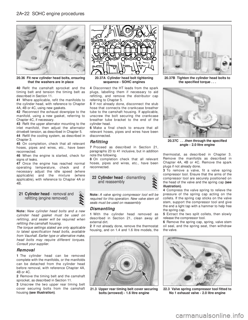
housing (see illustration).4Disconnect the HT leads from the spark
plugs, labelling them if necessary to aid
refitting, and remove the distributor cap
referring to Chapter 5.
5If not already done, disconnect the stub
hose that connects the crankcase breather
tube to the camshaft housing. If applicable,
unscrew the bolt securing the crankcase
breather tube bracket to the end of the
cylinder head.
6Make a final check to ensure that all
relevant hoses, pipes and wires have been
disconnected.
Refitting
7Proceed as described in Section 21,
paragraphs 23 to 41 inclusive, but in addition
note the following.
8On completion check that all relevant
hoses, pipes and wires, etc., have been
reconnected.
22Cylinder head -dismantling
and reassembly
4
Note: A valve spring compressor tool will be
required for this operation. New valve stem oil
seals must be used on reassembly
Dismantling
1With the cylinder head removed as
described in Section 21, clean away all
external dirt.
2If not already done, remove the thermostat
housing, and on 1.4 and 1.6 litre models, thethermostat, as described in Chapter 3.
Remove the manifolds as described in
Chapter 4A, 4B or 4C. Remove the spark
plugs if not already done.
3To remove a valve, fit a valve spring
compressor tool. Ensure that the arms of the
compressor tool are securely positioned on
the head of the valve and the spring cap (see
illustration).
4Compress the valve spring to relieve the
pressure of the spring cap acting on the
collets. If the spring cap sticks on the valve
stem, support the compressor tool and give
the end a light tap with a hammer to help free
the spring cap.
5Extract the two split collets, then slowly
release the compressor tool.
6Remove the spring cap, spring, valve stem
oil seal, and the spring seat, then withdraw
the valve.
2A•22SOHC engine procedures
20.36 Fit new cylinder head bolts, ensuring
that the washers are in place20.37B Tighten the cylinder head bolts to
the specified torque . . .
22.3 Valve spring compressor tool fitted to
No 1 exhaust valve - 2.0 litre engine21.3 Upper rear timing belt cover securing
bolts (arrowed) - 1.6 litre engine
20.37C . . .then through the specified
angle - 2.0 litre engine
20.37A Cylinder head bolt tightening
sequence - SOHC engines
Page 248 of 525

MOTTest Checks REF•9
Seat belts and seats
Note: The following checks are applicable to
all seat belts, front and rear.
MExamine the webbing of all the belts
(including rear belts if fitted) for cuts, serious
fraying or deterioration. Fasten and unfasten
each belt to check the buckles. If applicable,
check the retracting mechanism. Check the
security of all seat belt mountings accessible
from inside the vehicle.
MThe front seats themselves must be
securely attached and the backrests must
lock in the upright position.
Doors
MBoth front doors must be able to be opened
and closed from outside and inside, and must
latch securely when closed.
Vehicle identification
MNumber plates must be in good condition,
secure and legible, with letters and numbers
correctly spaced – spacing at (A) should be
twice that at (B).
MThe VIN plate and/or homologation plate
must be legible.
Electrical equipment
MSwitch on the ignition and check the
operation of the horn.
MCheck the windscreen washers and wipers,
examining the wiper blades; renew damaged
or perished blades. Also check the operation
of the stop-lights.
MCheck the operation of the sidelights and
number plate lights. The lenses and reflectors
must be secure, clean and undamaged.
MCheck the operation and alignment of the
headlights. The headlight reflectors must not
be tarnished and the lenses must be
undamaged.
MSwitch on the ignition and check the
operation of the direction indicators (including
the instrument panel tell-tale) and the hazard
warning lights. Operation of the sidelights and
stop-lights must not affect the indicators - if it
does, the cause is usually a bad earth at the
rear light cluster.
MCheck the operation of the rear foglight(s),
including the warning light on the instrument
panel or in the switch.
Footbrake
MExamine the master cylinder, brake pipes
and servo unit for leaks, loose mountings,
corrosion or other damage.
MThe fluid reservoir must be secure and the
fluid level must be between the upper (A) and
lower (B) markings.MInspect both front brake flexible hoses for
cracks or deterioration of the rubber. Turn the
steering from lock to lock, and ensure that the
hoses do not contact the wheel, tyre, or any
part of the steering or suspension mechanism.
With the brake pedal firmly depressed, check
the hoses for bulges or leaks under pressure.
Steering and suspension
MHave your assistant turn the steering wheel
from side to side slightly, up to the point where
the steering gear just begins to transmit this
movement to the roadwheels. Check for
excessive free play between the steering
wheel and the steering gear, indicating wear or
insecurity of the steering column joints, the
column-to-steering gear coupling, or the
steering gear itself.
MHave your assistant turn the steering wheel
more vigorously in each direction, so that the
roadwheels just begin to turn. As this is done,
examine all the steering joints, linkages,
fittings and attachments. Renew any
component that shows signs of wear or
damage. On vehicles with power steering,
check the security and condition of the
steering pump, drivebelt and hoses.
MCheck that the vehicle is standing level,
and at approximately the correct ride height.
Shock absorbers
MDepress each corner of the vehicle in turn,
then release it. The vehicle should rise and
then settle in its normal position. If the vehicle
continues to rise and fall, the shock absorber
is defective. A shock absorber which has
seized will also cause the vehicle to fail.
2Checks carried out
WITH THE VEHICLE ON THE
GROUND
REF
Page 251 of 525
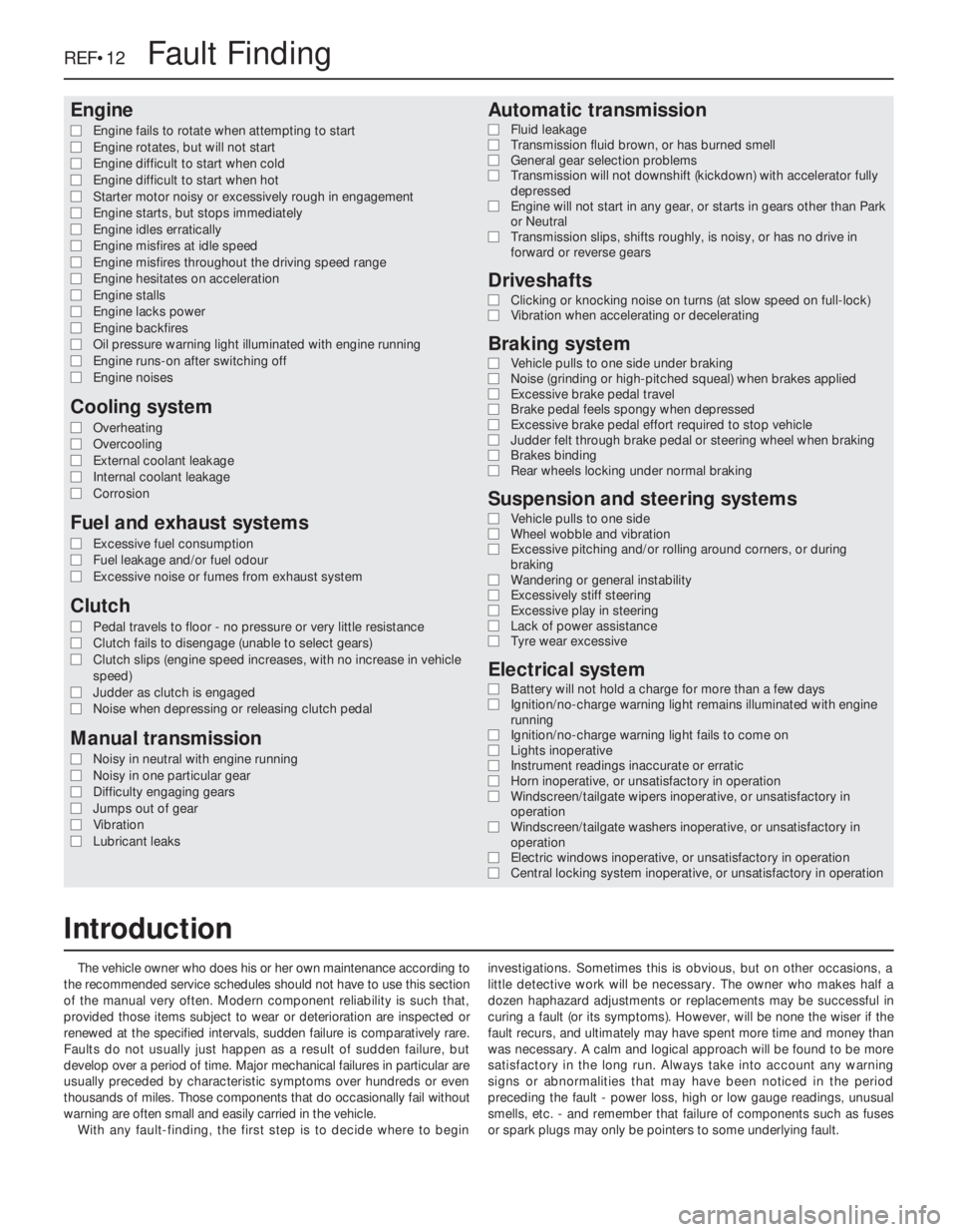
Engine
m mEngine fails to rotate when attempting to start
m mEngine rotates, but will not start
m mEngine difficult to start when cold
m mEngine difficult to start when hot
m mStarter motor noisy or excessively rough in engagement
m mEngine starts, but stops immediately
m mEngine idles erratically
m mEngine misfires at idle speed
m mEngine misfires throughout the driving speed range
m mEngine hesitates on acceleration
m mEngine stalls
m mEngine lacks power
m mEngine backfires
m mOil pressure warning light illuminated with engine running
m mEngine runs-on after switching off
m mEngine noises
Cooling system
m
mOverheating
m mOvercooling
m mExternal coolant leakage
m mInternal coolant leakage
m mCorrosion
Fuel and exhaust systems
m
mExcessive fuel consumption
m mFuel leakage and/or fuel odour
m mExcessive noise or fumes from exhaust system
Clutch
m
mPedal travels to floor - no pressure or very little resistance
m mClutch fails to disengage (unable to select gears)
m mClutch slips (engine speed increases, with no increase in vehicle
speed)
m mJudder as clutch is engaged
m mNoise when depressing or releasing clutch pedal
Manual transmission
m
mNoisy in neutral with engine running
m mNoisy in one particular gear
m mDifficulty engaging gears
m mJumps out of gear
m mVibration
m mLubricant leaks
Automatic transmission
m
mFluid leakage
m mTransmission fluid brown, or has burned smell
m mGeneral gear selection problems
m mTransmission will not downshift (kickdown) with accelerator fully
depressed
m mEngine will not start in any gear, or starts in gears other than Park
or Neutral
m mTransmission slips, shifts roughly, is noisy, or has no drive in
forward or reverse gears
Driveshafts
m mClicking or knocking noise on turns (at slow speed on full-lock)
m mVibration when accelerating or decelerating
Braking system
m
mVehicle pulls to one side under braking
m mNoise (grinding or high-pitched squeal) when brakes applied
m mExcessive brake pedal travel
m mBrake pedal feels spongy when depressed
m mExcessive brake pedal effort required to stop vehicle
m mJudder felt through brake pedal or steering wheel when braking
m mBrakes binding
m mRear wheels locking under normal braking
Suspension and steering systems
m
mVehicle pulls to one side
m mWheel wobble and vibration
m mExcessive pitching and/or rolling around corners, or during
braking
m mWandering or general instability
m mExcessively stiff steering
m mExcessive play in steering
m mLack of power assistance
m mTyre wear excessive
Electrical system
m
mBattery will not hold a charge for more than a few days
m mIgnition/no-charge warning light remains illuminated with engine
running
m mIgnition/no-charge warning light fails to come on
m mLights inoperative
m mInstrument readings inaccurate or erratic
m mHorn inoperative, or unsatisfactory in operation
m mWindscreen/tailgate wipers inoperative, or unsatisfactory in
operation
m mWindscreen/tailgate washers inoperative, or unsatisfactory in
operation
m mElectric windows inoperative, or unsatisfactory in operation
m mCentral locking system inoperative, or unsatisfactory in operation
The vehicle owner who does his or her own maintenance according to
the recommended service schedules should not have to use this section
of the manual very often. Modern component reliability is such that,
provided those items subject to wear or deterioration are inspected or
renewed at the specified intervals, sudden failure is comparatively rare.
Faults do not usually just happen as a result of sudden failure, but
develop over a period of time. Major mechanical failures in particular are
usually preceded by characteristic symptoms over hundreds or even
thousands of miles. Those components that do occasionally fail without
warning are often small and easily carried in the vehicle.
With any fault-finding, the first step is to decide where to begininvestigations. Sometimes this is obvious, but on other occasions, a
little detective work will be necessary. The owner who makes half a
dozen haphazard adjustments or replacements may be successful in
curing a fault (or its symptoms). However, will be none the wiser if the
fault recurs, and ultimately may have spent more time and money than
was necessary. A calm and logical approach will be found to be more
satisfactory in the long run. Always take into account any warning
signs or abnormalities that may have been noticed in the period
preceding the fault - power loss, high or low gauge readings, unusual
smells, etc. - and remember that failure of components such as fuses
or spark plugs may only be pointers to some underlying fault.
REF•12Fault Finding
Introduction
Page 258 of 525
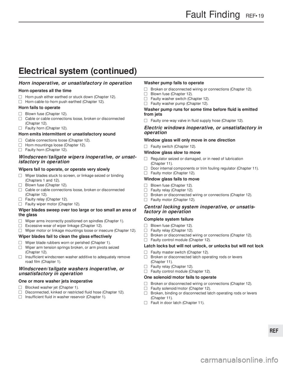
Horn inoperative, or unsatisfactory in operation
Horn operates all the time
MHorn push either earthed or stuck down (Chapter 12).
MHorn cable-to-horn push earthed (Chapter 12).
Horn fails to operate
MBlown fuse (Chapter 12).
MCable or cable connections loose, broken or disconnected
(Chapter 12).
MFaulty horn (Chapter 12).
Horn emits intermittent or unsatisfactory sound
MCable connections loose (Chapter 12).
MHorn mountings loose (Chapter 12).
MFaulty horn (Chapter 12).
Windscreen/tailgate wipers inoperative, or unsat-
isfactory in operation
Wipers fail to operate, or operate very slowly
MWiper blades stuck to screen, or linkage seized or binding
(Chapters 1 and 12).
MBlown fuse (Chapter 12).
MCable or cable connections loose, broken or disconnected
(Chapter 12).
MFaulty relay (Chapter 12).
MFaulty wiper motor (Chapter 12).
Wiper blades sweep over too large or too small an area of
the glass
MWiper arms incorrectly positioned on spindles (Chapter 1).
MExcessive wear of wiper linkage (Chapter 12).
MWiper motor or linkage mountings loose or insecure (Chapter 12).
Wiper blades fail to clean the glass effectively
MWiper blade rubbers worn or perished (Chapter 1).
MWiper arm tension springs broken, or arm pivots seized
(Chapter 12).
MInsufficient windscreen washer additive to adequately remove
road film (Chapter 1).
Windscreen/tailgate washers inoperative, or
unsatisfactory in operation
One or more washer jets inoperative
MBlocked washer jet (Chapter 1).
MDisconnected, kinked or restricted fluid hose (Chapter 12).
MInsufficient fluid in washer reservoir (Chapter 1).
Washer pump fails to operate
MBroken or disconnected wiring or connections (Chapter 12).
MBlown fuse (Chapter 12).
MFaulty washer switch (Chapter 12).
MFaulty washer pump (Chapter 12).
Washer pump runs for some time before fluid is emitted
from jets
MFaulty one-way valve in fluid supply hose (Chapter 12).
Electric windows inoperative, or unsatisfactory in
operation
Window glass will only move in one direction
MFaulty switch (Chapter 12).
Window glass slow to move
MRegulator seized or damaged, or in need of lubrication
(Chapter 11).
MDoor internal components or trim fouling regulator (Chapter 11).
MFaulty motor (Chapter 12).
Window glass fails to move
MBlown fuse (Chapter 12).
MFaulty relay (Chapter 12).
MBroken or disconnected wiring or connections (Chapter 12).
MFaulty motor (Chapter 12).
Central locking system inoperative, or unsatis-
factory in operation
Complete system failure
MBlown fuse (Chapter 12).
MFaulty relay (Chapter 12).
MBroken or disconnected wiring or connections (Chapter 12).
MFaulty control module (Chapter 12).
Latch locks but will not unlock, or unlocks but will not lock
MFaulty master switch (Chapter 12).
MBroken or disconnected latch operating rods or levers
(Chapter 11).
MFaulty relay (Chapter 12).
MFaulty control module (Chapter 12).
One solenoid/motor fails to operate
MBroken or disconnected wiring or connections (Chapter 12).
MFaulty solenoid/motor (Chapter 12).
MBroken, binding or disconnected latch operating rods or levers
(Chapter 11).
MFault in door latch (Chapter 11).
Fault Finding REF•19
REF
Electrical system (continued)