1988 OPEL CALIBRA brake pads replacement
[x] Cancel search: brake pads replacementPage 139 of 525

5If any one of the shoes has worn below the
specified limit, all four handbrake shoes must
be renewed as a set, as follows.
SOHC models
Removal
6Clean the dust and dirt from the various
components, but take care not to inhale it.
7Disconnect the handbrake cable and the
return spring from the handbrake operating
lever at the brake backplate. If necessary,
slacken the handbrake cable adjustment, with
reference to Section 26.
8Remove the shoe hold-down pins, springs
and cups by depressing the cups and turning
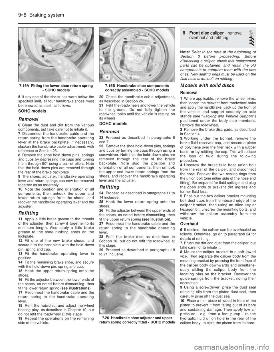
them through 90°using a pair of pliers. Note
that the hold-down pins are removed through
the rear of the brake backplate.
9The shoes, adjuster, handbrake operating
lever and return springs can now be removed
together as an assembly.
10Note the position and orientation of all
components, then unhook the upper and
lower return springs from the shoes, and
recover the handbrake operating lever and the
adjuster.
Refitting
11Apply a little brake grease to the threads
of the adjuster, then screw it together to its
minimum length. Also apply a little brake
grease to the shoe rubbing areas on the
lockplate.
12Fit one of the new brake shoes, and
secure it to the backplate with the hold-down
pin, spring and cup.
13Fit the handbrake operating lever in
position.
14Fit the remaining brake shoe, and secure
with the hold-down pin, spring and cup.
15Hook the upper return spring onto the
shoes.
16Fit the adjuster between the lower ends of
the shoes, as noted before dismantling, then
fit the lower return spring (see illustrations).
17Reconnect the handbrake cable and the
return spring to the handbrake operating
lever.
18Refit the hub/disc, and adjust the wheel
bearing play, as described in Chapter 10, but
do not refit the roadwheel at this stage.
19Repeat the operations on the remaining
side of the vehicle.20Check the handbrake cable adjustment,
as described in Section 26.
21Refit the roadwheels and lower the vehicle
to the ground. Do not fully tighten the
roadwheel bolts until the vehicle is resting on
its wheels.
DOHC models
Removal
22Proceed as described in paragraphs 6
and 7.
23Remove the shoe hold-down pins, springs
and cups by turning the cups through using a
screwdriver. Note that the hold-down pins are
removed through the rear of the brake
backplate. Note also the position and
orientation of all components, then unhook
the upper and lower return springs from the
shoes, and recover the handbrake operating
lever and the adjuster.
Refitting
24Proceed as described in paragraphs 11 to
14 inclusive.
25Hook the lower return spring onto the
shoes.
26Fit the adjuster between the upper ends of
the shoes, as noted before dismantling, then
fit the upper return spring (see illustration).
27Reconnect the handbrake cable and the
return spring to the handbrake operating
lever.
28Refit the brake disc as described in
Section 10, but do not refit the roadwheel at
this stage.
29Proceed as described in paragraphs 19
to 21 inclusive.
8Front disc caliper - removal,
overhaul and refitting
3
Note: Refer to the note at the beginning of
Section 3 before proceeding. Before
dismantling a caliper, check that replacement
parts can be obtained, and retain the old
components to compare them with the new
ones. New sealing rings must be used on the
fluid hose union bolt on refitting
Models with solid discs
Removal
1Where applicable, remove the wheel trims,
then loosen the relevant front roadwheel bolts
and apply the handbrake. Jack up the front of
the vehicle, and support securely on axle
stands (see “Jacking and Vehicle Support”)
positioned under the body side members.
Remove the roadwheel.
2Remove the brake disc pads, as described
in Section 4.
3Working under the bonnet, remove the
brake fluid reservoir cap, and secure a piece
of polythene over the filler neck with a rubber
band, or by refitting the cap. This will reduce
the loss of fluid during the following
procedure.
4Unscrew the brake fluid hose union bolt
from the rear of the caliper, and disconnect
the hose. Recover the two sealing rings from
the union bolt (one either side of the hose end
fitting). Be prepared for fluid spillage, and plug
the open ends to prevent dirt ingress and
further fluid loss.
5Prise out the two caliper bracket mounting
bolt dust caps from the inboard edge of the
caliper bracket, then using an Allen key or
hexagon bit, unscrew the mounting bolts, and
withdraw the caliper assembly from the
vehicle.
Overhaul
6If desired, the caliper can be overhauled as
follows. Otherwise, go on to paragraph 24 for
details of refitting.
7Brush the dirt and dust from the caliper, but
take care not to inhale it.
8Mount the caliper bracket in a soft-jawed
vice. Then separate the caliper body from the
mounting bracket by pressing the front face of
the caliper body downwards and simultane-
ously sliding the caliper body from the
locating pins on the bracket. Recover the
guide springs from the bracket, noting their
orientation.
9Using a screwdriver, prise the dust seal
retaining clip from the piston dust seal, then
carefully prise off the dust seal.
10Place a thin piece of wood in front of the
piston to prevent it from falling out of its bore
and sustaining damage. Then apply low air
pressure - e.g. from a foot pump - to the
hydraulic fluid union hole in the rear of the
caliper body, to eject the piston from its bore.
9•8Braking system
7.16A Fitting the lower shoe return spring
- SOHC models
7.26 Handbrake shoe adjuster and upper
return spring correctly fitted - DOHC models
7.16B Handbrake shoe components
correctly assembled - SOHC models
Page 140 of 525

11Remove the wood and carefully withdraw
the piston.
12Carefully prise the seal from the groove in
the caliper piston bore, using a plastic or
wooden instrument.
13Inspect the surfaces of the piston and its
bore in the caliper for scoring, or evidence of
metal-to-metal contact. If evident, renew the
complete caliper assembly.
14If the piston and bore are in good
condition, discard the seals and obtain a
repair kit, which will contain all the necessary
renewable items.
15Clean the piston and cylinder bore with
brake fluid or methylated spirit, nothing else!
16Begin reassembly by fitting the seal into
the caliper bore.
17Locate the dust seal in its groove in the
piston. Dip the piston in clean brake fluid and
insert it squarely into the cylinder. Check that
the cutaway recesses in the piston are
positioned horizontally. If necessary, carefully
turn the piston to its correct position.
18When the piston has been partially
depressed, engage the dust seal with the rim
of the caliper bore, and fit the retaining clip.
19Push the piston further into its bore, but
not as far as the stop, ensuring that it does
not jam.
20If desired, the caliper body locating pin
rubbers can be renewed. Extract the nylon
compression sleeve from within each rubber,
then carefully compress the rubber shoulder,
and push the rubber through the hole in the
caliper body to remove it from the inboard
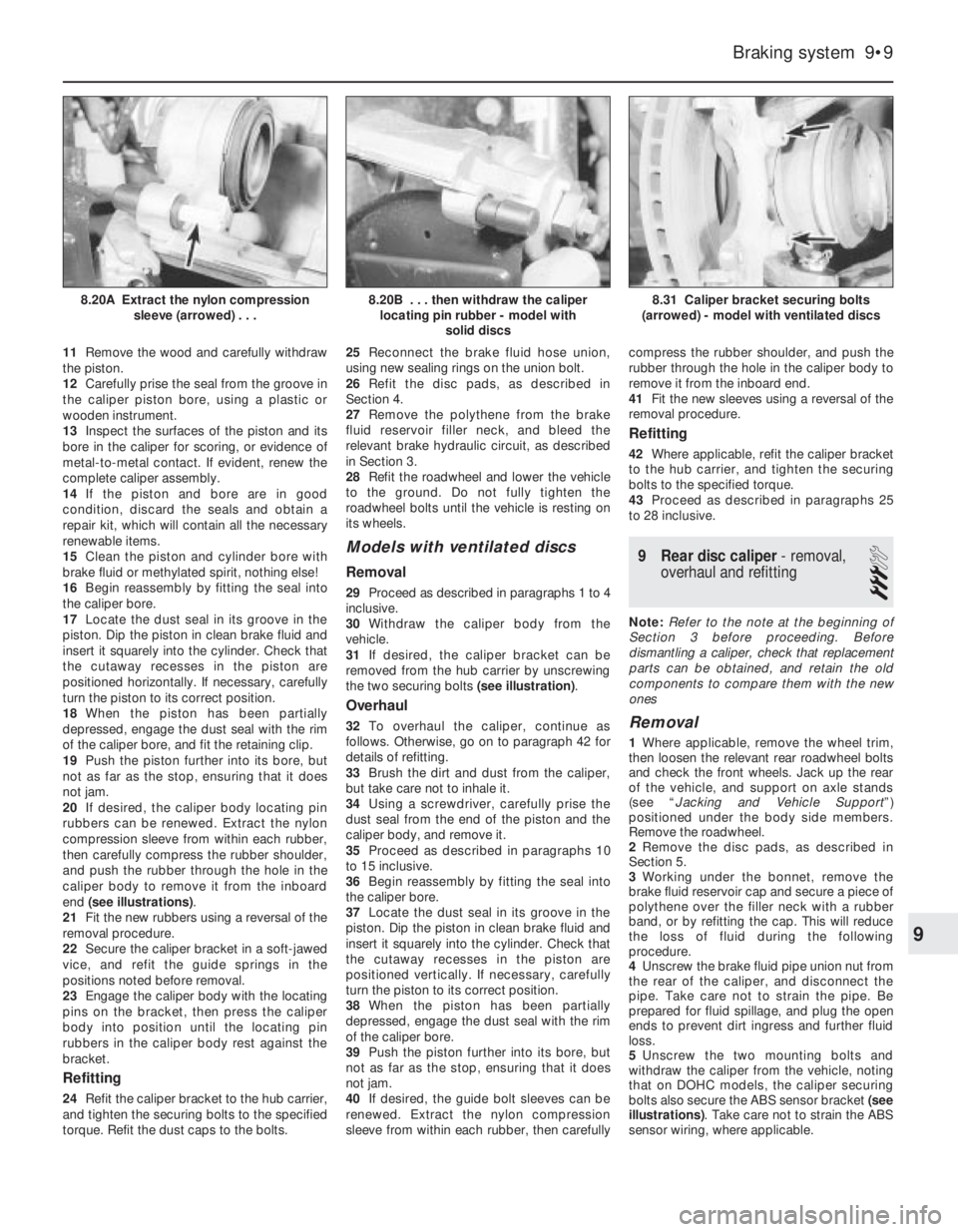
end (see illustrations).
21Fit the new rubbers using a reversal of the
removal procedure.
22Secure the caliper bracket in a soft-jawed
vice, and refit the guide springs in the
positions noted before removal.
23Engage the caliper body with the locating
pins on the bracket, then press the caliper
body into position until the locating pin
rubbers in the caliper body rest against the
bracket.
Refitting
24Refit the caliper bracket to the hub carrier,
and tighten the securing bolts to the specified
torque. Refit the dust caps to the bolts.25Reconnect the brake fluid hose union,
using new sealing rings on the union bolt.
26Refit the disc pads, as described in
Section 4.
27Remove the polythene from the brake
fluid reservoir filler neck, and bleed the
relevant brake hydraulic circuit, as described
in Section 3.
28Refit the roadwheel and lower the vehicle
to the ground. Do not fully tighten the
roadwheel bolts until the vehicle is resting on
its wheels.
Models with ventilated discs
Removal
29Proceed as described in paragraphs 1 to 4
inclusive.
30Withdraw the caliper body from the
vehicle.
31If desired, the caliper bracket can be
removed from the hub carrier by unscrewing
the two securing bolts (see illustration).
Overhaul
32To overhaul the caliper, continue as
follows. Otherwise, go on to paragraph 42 for
details of refitting.
33Brush the dirt and dust from the caliper,
but take care not to inhale it.
34Using a screwdriver, carefully prise the
dust seal from the end of the piston and the
caliper body, and remove it.
35Proceed as described in paragraphs 10
to 15 inclusive.
36Begin reassembly by fitting the seal into
the caliper bore.
37Locate the dust seal in its groove in the
piston. Dip the piston in clean brake fluid and
insert it squarely into the cylinder. Check that
the cutaway recesses in the piston are
positioned vertically. If necessary, carefully
turn the piston to its correct position.
38When the piston has been partially
depressed, engage the dust seal with the rim
of the caliper bore.
39Push the piston further into its bore, but
not as far as the stop, ensuring that it does
not jam.
40If desired, the guide bolt sleeves can be
renewed. Extract the nylon compression
sleeve from within each rubber, then carefullycompress the rubber shoulder, and push the
rubber through the hole in the caliper body to
remove it from the inboard end.
41Fit the new sleeves using a reversal of the
removal procedure.
Refitting
42Where applicable, refit the caliper bracket
to the hub carrier, and tighten the securing
bolts to the specified torque.
43Proceed as described in paragraphs 25
to 28 inclusive.
9Rear disc caliper - removal,
overhaul and refitting
3
Note: Refer to the note at the beginning of
Section 3 before proceeding. Before
dismantling a caliper, check that replacement
parts can be obtained, and retain the old
components to compare them with the new
ones
Removal
1Where applicable, remove the wheel trim,
then loosen the relevant rear roadwheel bolts
and check the front wheels. Jack up the rear
of the vehicle, and support on axle stands
(see “Jacking and Vehicle Support”)
positioned under the body side members.
Remove the roadwheel.
2Remove the disc pads, as described in
Section 5.
3Working under the bonnet, remove the
brake fluid reservoir cap and secure a piece of
polythene over the filler neck with a rubber
band, or by refitting the cap. This will reduce
the loss of fluid during the following
procedure.
4Unscrew the brake fluid pipe union nut from
the rear of the caliper, and disconnect the
pipe. Take care not to strain the pipe. Be
prepared for fluid spillage, and plug the open
ends to prevent dirt ingress and further fluid
loss.
5Unscrew the two mounting bolts and
withdraw the caliper from the vehicle, noting
that on DOHC models, the caliper securing
bolts also secure the ABS sensor bracket (see
illustrations). Take care not to strain the ABS
sensor wiring, where applicable.
Braking system 9•9
8.31 Caliper bracket securing bolts
(arrowed) - model with ventilated discs8.20B . . . then withdraw the caliper
locating pin rubber - model with
solid discs8.20A Extract the nylon compression
sleeve (arrowed) . . .
9
Page 142 of 525

Rear disc - DOHC models
Removal
15Where applicable, remove the roadwheel
bolt and spacer used when checking the disc.
16Remove the disc pads, as described in
Section 5.
17Remove the brake caliper with reference
to Section 9, but leave the hydraulic fluid pipe
connected. Move the caliper to one side, and
suspend it using wire or string to avoid
straining the pipe.
18Remove the securing screw and withdraw
the disc from the hub (see illustration). If the
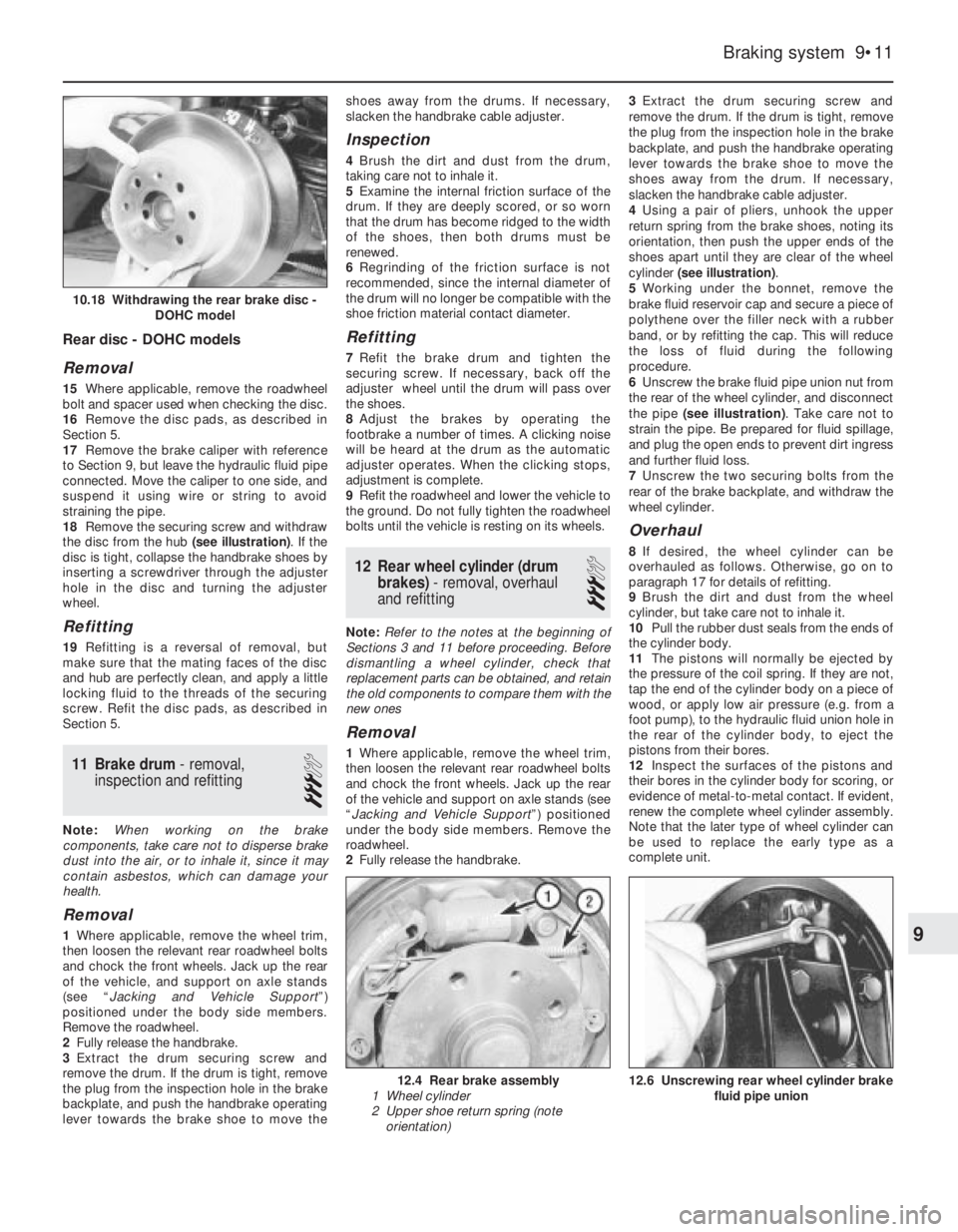
disc is tight, collapse the handbrake shoes by
inserting a screwdriver through the adjuster
hole in the disc and turning the adjuster
wheel.
Refitting
19Refitting is a reversal of removal, but
make sure that the mating faces of the disc
and hub are perfectly clean, and apply a little
locking fluid to the threads of the securing
screw. Refit the disc pads, as described in
Section 5.
11Brake drum - removal,
inspection and refitting
3
Note: When working on the brake
components, take care not to disperse brake
dust into the air, or to inhale it, since it may
contain asbestos, which can damage your
health.
Removal
1Where applicable, remove the wheel trim,
then loosen the relevant rear roadwheel bolts
and chock the front wheels. Jack up the rear
of the vehicle, and support on axle stands
(see “Jacking and Vehicle Support”)
positioned under the body side members.
Remove the roadwheel.
2Fully release the handbrake.
3Extract the drum securing screw and
remove the drum. If the drum is tight, remove
the plug from the inspection hole in the brake
backplate, and push the handbrake operating
lever towards the brake shoe to move theshoes away from the drums. If necessary,
slacken the handbrake cable adjuster.
Inspection
4Brush the dirt and dust from the drum,
taking care not to inhale it.
5Examine the internal friction surface of the
drum. If they are deeply scored, or so worn
that the drum has become ridged to the width
of the shoes, then both drums must be
renewed.
6Regrinding of the friction surface is not
recommended, since the internal diameter of
the drum will no longer be compatible with the
shoe friction material contact diameter.
Refitting
7Refit the brake drum and tighten the
securing screw. If necessary, back off the
adjuster wheel until the drum will pass over
the shoes.
8Adjust the brakes by operating the
footbrake a number of times. A clicking noise
will be heard at the drum as the automatic
adjuster operates. When the clicking stops,
adjustment is complete.
9Refit the roadwheel and lower the vehicle to
the ground. Do not fully tighten the roadwheel
bolts until the vehicle is resting on its wheels.
12Rear wheel cylinder (drum
brakes) - removal, overhaul
and refitting
3
Note: Refer to the notes at the beginning of
Sections 3 and 11 before proceeding. Before
dismantling a wheel cylinder, check that
replacement parts can be obtained, and retain
the old components to compare them with the
new ones
Removal
1Where applicable, remove the wheel trim,
then loosen the relevant rear roadwheel bolts
and chock the front wheels. Jack up the rear
of the vehicle and support on axle stands (see
“Jacking and Vehicle Support”) positioned
under the body side members. Remove the
roadwheel.
2Fully release the handbrake.3Extract the drum securing screw and
remove the drum. If the drum is tight, remove
the plug from the inspection hole in the brake
backplate, and push the handbrake operating
lever towards the brake shoe to move the
shoes away from the drum. If necessary,
slacken the handbrake cable adjuster.
4Using a pair of pliers, unhook the upper
return spring from the brake shoes, noting its
orientation, then push the upper ends of the
shoes apart until they are clear of the wheel
cylinder (see illustration).
5Working under the bonnet, remove the
brake fluid reservoir cap and secure a piece of
polythene over the filler neck with a rubber
band, or by refitting the cap. This will reduce
the loss of fluid during the following
procedure.
6Unscrew the brake fluid pipe union nut from
the rear of the wheel cylinder, and disconnect
the pipe (see illustration). Take care not to
strain the pipe. Be prepared for fluid spillage,
and plug the open ends to prevent dirt ingress
and further fluid loss.
7Unscrew the two securing bolts from the
rear of the brake backplate, and withdraw the
wheel cylinder.
Overhaul
8If desired, the wheel cylinder can be
overhauled as follows. Otherwise, go on to
paragraph 17 for details of refitting.
9Brush the dirt and dust from the wheel
cylinder, but take care not to inhale it.
10Pull the rubber dust seals from the ends of
the cylinder body.
11The pistons will normally be ejected by
the pressure of the coil spring. If they are not,
tap the end of the cylinder body on a piece of
wood, or apply low air pressure (e.g. from a
foot pump), to the hydraulic fluid union hole in
the rear of the cylinder body, to eject the
pistons from their bores.
12Inspect the surfaces of the pistons and
their bores in the cylinder body for scoring, or
evidence of metal-to-metal contact. If evident,
renew the complete wheel cylinder assembly.
Note that the later type of wheel cylinder can
be used to replace the early type as a
complete unit.
Braking system 9•11
12.6 Unscrewing rear wheel cylinder brake
fluid pipe union12.4 Rear brake assembly
1 Wheel cylinder
2 Upper shoe return spring (note
orientation)
10.18 Withdrawing the rear brake disc -
DOHC model
9