1988 OPEL CALIBRA washer hose
[x] Cancel search: washer hosePage 128 of 525
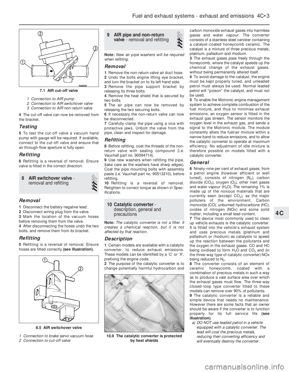
4The cut-off valve can now be removed from
the bracket.
Testing
5To test the cut-off valve a vacuum hand
pump with gauge will be required. If available,
connect to the cut-off valve and ensure that
air through-flow aperture is fully open.
Refitting
6Refitting is a reversal of removal. Ensure
valve is fitted in the correct direction.
8AIR switchover valve -
removal and refitting
3
Removal
1Disconnect the battery negative lead.
2Disconnect wiring plug from the valve.
3Mark the location of the vacuum hoses
before removing them from the valve.
4After disconnecting the hoses undo the two
bolts, and remove them from its bracket.
Refitting
5Refitting is a reversal of removal. Ensure
hoses are fitted correctly (see illustration).
9AIR pipe and non-return
valve - removal and refitting
3
Note:New air pipe washers will be required
when refitting.
Removal
1Remove the non-return valve air duct hose.
2Undo the bolts engine lifting eye bracket,
and turn the bracket on to its left hand side.
3Remove the pipe support bracket by
releasing its three bolts.
4Remove the heat shield that is secured by
two bolts.
5The air pipe can now be removed by
releasing the two securing bolts.
6If necessary the non-return valve can now
be disconnected.
7Carefully clamp the pipe using a vice with
protective jaws. Unbolt the valve from the
pipe, clean and inspect for damage.
Refitting
8Before refitting, coat the threads of the non-
return valve with sealing compound (i.e.
Vauxhall part no. 90094714).
9Use new washers when refitting the pipe,
(take care as the washers have sharp edges).
Coat the pipe mounting bolts with assembly
paste (i.e. Vauxhall part no. 90513210), before
refitting.
10Refitting is a reversal of removal.
Retighten to correct torque as shown in Spec-
ifications.
10Catalytic converter -
description, general and
precautions
Note: The catalytic converter is not a filter. It
creates a chemical reaction, but it is not
affected by that reaction.
Description
1Certain models are available with a catalytic
converter, to reduce exhaust emissions.
These models can be identified by a ‘C’ or ‘X’,
prefixing the engine code.
2The purpose of the catalytic converter is to
change potentially harmful hydrocarbon andcarbon monoxide exhaust gases into harmless
gases and water vapour. The converter
consists of a stainless steel canister containing
a catalyst-coated honeycomb ceramic. The
catalyst is a mixture of three precious metals,
platinum, palladium and rhodium.
3The exhaust gases pass freely through the
honeycomb, where the catalyst speeds up the
chemical change of the exhaust gases,
without being permanently altered itself.
4To avoid damage to the catalyst, the engine
must be kept properly tuned, and unleaded
petrol must always be used. Normal leaded
petrol will “poison” the catalyst, and must not
be used.
5To enable the Motronic engine management
system to achieve complete combustion of the
fuel mixture, and thus to minimise exhaust
emissions, an oxygen sensor is fitted in the
exhaust gas stream. The sensor monitors the
oxygen level in the exhaust gas, and sends a
signal to the Motronic module. The module
constantly alters the fuel/air mixture within a
narrow band to reduce emissions, and to allow
the catalytic converter to operate at maximum
efficiency. No adjustment of idle mixture is
therefore possible on models fitted with a
catalytic converter.
General
6Ninety-nine per cent of exhaust gases, from
a petrol engine (however efficient or well
tuned), consists of nitrogen (N
2), carbon
dioxide (CO
2), oxygen (O2), other inert gases
and water vapour (H
2O). The remaining 1% is
made up of the noxious materials that are
currently seen (except CO
2), as the major
polluters of the environment. Carbon
monoxide (CO), unburned hydrocarbons (HC),
oxides of nitrogen (NOx) and some solid
matter, including a small lead content.
7The device most commonly used to clean
up vehicle exhausts is the catalytic converter.
It is fitted into the vehicle’s exhaust system
and uses precious metals (platinum and
palladium or rhodium) as catalysts to speed
up the reaction between the pollutants and
the oxygen in the exhaust gases. CO and HC
being oxidised to form H
2O and CO2and (in
the three-way type of catalytic converter) NOx
being reduced to N
2.
8The converter consists of an element of
ceramic honeycomb, coated with a
combination of precious metals in such a way
as to produce a vast surface area over which
the exhaust gases must flow. The three-way
closed-loop type converter fitted to these
models can remove over 90% of pollutants.
9The catalytic converter is a reliable and
simple device that needs no maintenance.
However there are some facts that an owner
should be aware if the converter is to function
properly for its full service life (see
illustration).
a)DO NOT use leaded petrol in a vehicle
equipped with a catalytic converter. The
lead will coat the precious metals,
reducing their converting efficiency and
will eventually destroy the converter.
Fuel and exhaust systems - exhaust and emissions 4C•3
10.9 The catalytic converter is protected
by heat shields
8.5 AIR switchover valve
1 Connection to brake servo vacuum hose
2 Connection to cut-off valve
7.1 AIR cut-off valve
1 Connection to AIR pump
2 Connection to AIR switchover valve
3 Connection to AIR non-return valve
4C
Page 170 of 525
Refitting
5Refitting is a reversal of the removal
procedure, ensuring that the wiring plugs are
correctly reconnected and that the unit is
located securely.
36Knock sensor and module
(X16 SZ models) - removal
and refitting
3
Removal
1The knock sensor fitted to the X16 SZ
engine is located on the cylinder block below
the inlet manifold, between cylinders 2 and 3.
2Disconnect the battery negative lead.
3Remove the wiring and unscrew the unit
from the block.
4The module and control unit are located on
the left-hand side of the engine compartment
behind the battery. To remove, disconnect the
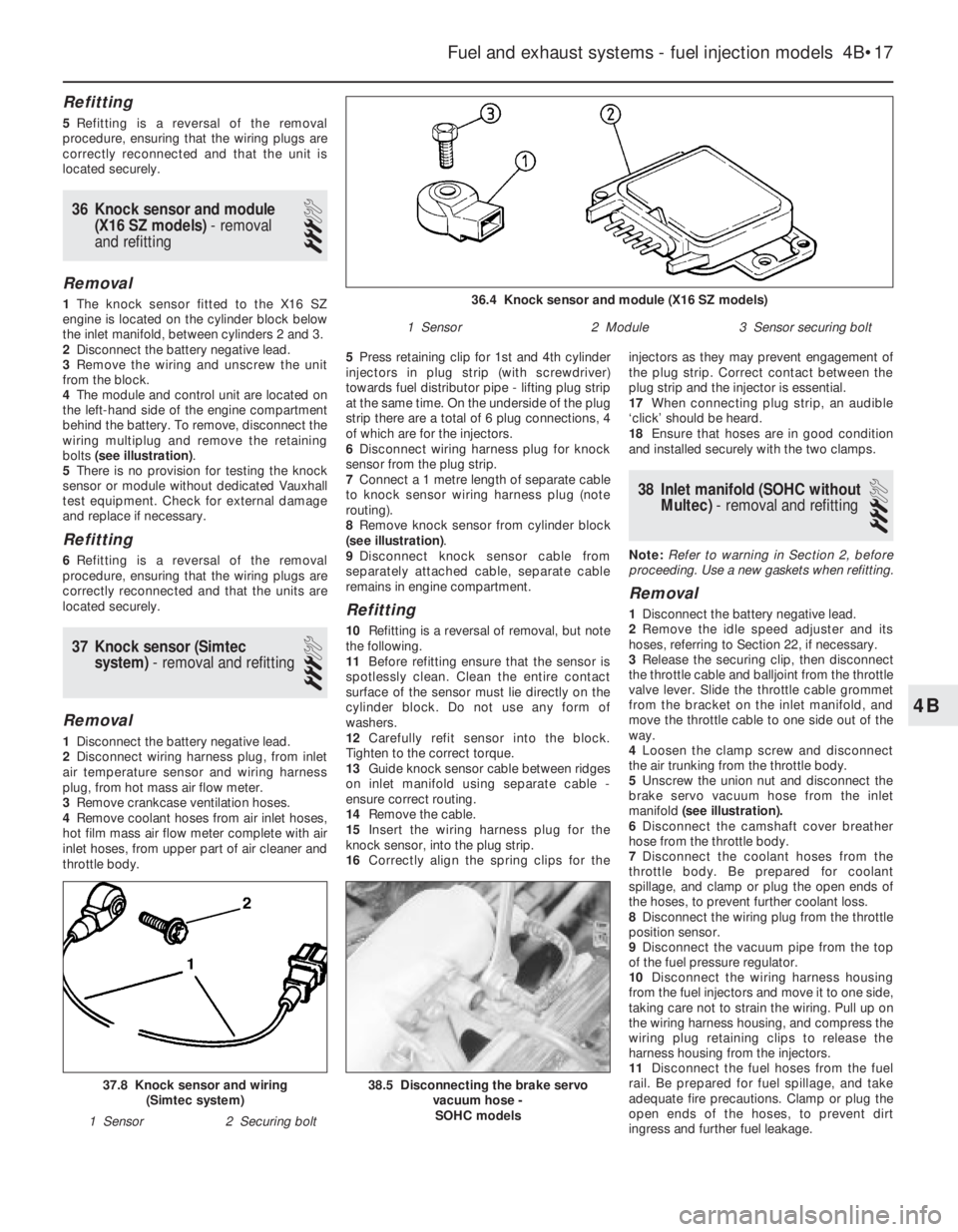
wiring multiplug and remove the retaining
bolts (see illustration).
5There is no provision for testing the knock
sensor or module without dedicated Vauxhall
test equipment. Check for external damage
and replace if necessary.
Refitting
6Refitting is a reversal of the removal
procedure, ensuring that the wiring plugs are
correctly reconnected and that the units are
located securely.
37Knock sensor (Simtec
system) - removal and refitting
3
Removal
1Disconnect the battery negative lead.
2Disconnect wiring harness plug, from inlet
air temperature sensor and wiring harness
plug, from hot mass air flow meter.
3Remove crankcase ventilation hoses.
4Remove coolant hoses from air inlet hoses,
hot film mass air flow meter complete with air
inlet hoses, from upper part of air cleaner and
throttle body.5Press retaining clip for 1st and 4th cylinder
injectors in plug strip (with screwdriver)
towards fuel distributor pipe - lifting plug strip
at the same time. On the underside of the plug
strip there are a total of 6 plug connections, 4
of which are for the injectors.
6Disconnect wiring harness plug for knock
sensor from the plug strip.
7Connect a 1 metre length of separate cable
to knock sensor wiring harness plug (note
routing).
8Remove knock sensor from cylinder block
(see illustration).
9Disconnect knock sensor cable from
separately attached cable, separate cable
remains in engine compartment.
Refitting
10Refitting is a reversal of removal, but note
the following.
11Before refitting ensure that the sensor is
spotlessly clean. Clean the entire contact
surface of the sensor must lie directly on the
cylinder block. Do not use any form of
washers.
12Carefully refit sensor into the block.
Tighten to the correct torque.
13Guide knock sensor cable between ridges
on inlet manifold using separate cable -
ensure correct routing.
14Remove the cable.
15Insert the wiring harness plug for the
knock sensor, into the plug strip.
16Correctly align the spring clips for theinjectors as they may prevent engagement of
the plug strip. Correct contact between the
plug strip and the injector is essential.
17When connecting plug strip, an audible
‘click’ should be heard.
18Ensure that hoses are in good condition
and installed securely with the two clamps.
38Inlet manifold (SOHC without
Multec) - removal and refitting
3
Note:Refer to warning in Section 2, before
proceeding. Use a new gaskets when refitting.
Removal
1Disconnect the battery negative lead.
2Remove the idle speed adjuster and its
hoses, referring to Section 22, if necessary.
3Release the securing clip, then disconnect
the throttle cable and balljoint from the throttle
valve lever. Slide the throttle cable grommet
from the bracket on the inlet manifold, and
move the throttle cable to one side out of the
way.
4Loosen the clamp screw and disconnect
the air trunking from the throttle body.
5Unscrew the union nut and disconnect the
brake servo vacuum hose from the inlet
manifold(see illustration).
6Disconnect the camshaft cover breather
hose from the throttle body.
7Disconnect the coolant hoses from the
throttle body. Be prepared for coolant
spillage, and clamp or plug the open ends of
the hoses, to prevent further coolant loss.
8Disconnect the wiring plug from the throttle
position sensor.
9Disconnect the vacuum pipe from the top
of the fuel pressure regulator.
10Disconnect the wiring harness housing
from the fuel injectors and move it to one side,
taking care not to strain the wiring. Pull up on
the wiring harness housing, and compress the
wiring plug retaining clips to release the
harness housing from the injectors.
11Disconnect the fuel hoses from the fuel
rail. Be prepared for fuel spillage, and take
adequate fire precautions. Clamp or plug the
open ends of the hoses, to prevent dirt
ingress and further fuel leakage.
Fuel and exhaust systems - fuel injection models 4B•17
38.5 Disconnecting the brake servo
vacuum hose -
SOHC models37.8 Knock sensor and wiring
(Simtec system)
1 Sensor2 Securing bolt
36.4 Knock sensor and module (X16 SZ models)
1 Sensor2 Module3 Sensor securing bolt
4B
Page 177 of 525
1•6Maintenance - component location
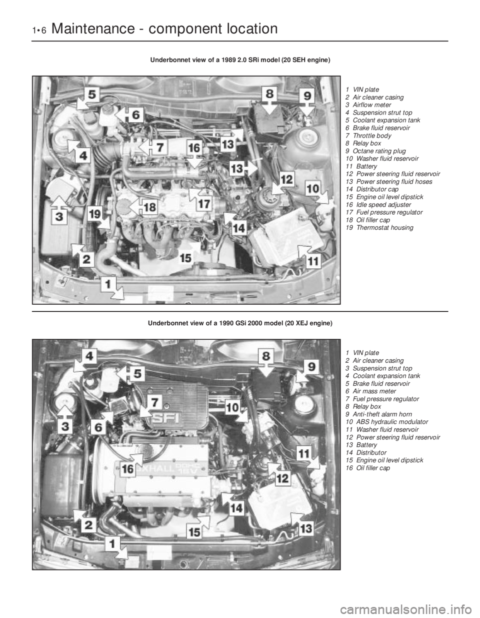
Underbonnet view of a 1989 2.0 SRi model (20 SEH engine)
1 VIN plate
2 Air cleaner casing
3 Airflow meter
4 Suspension strut top
5 Coolant expansion tank
6 Brake fluid reservoir
7 Throttle body
8 Relay box
9 Octane rating plug
10 Washer fluid reservoir
11 Battery
12 Power steering fluid reservoir
13 Power steering fluid hoses
14 Distributor cap
15 Engine oil level dipstick
16 Idle speed adjuster
17 Fuel pressure regulator
18 Oil filler cap
19 Thermostat housing
Underbonnet view of a 1990 GSi 2000 model (20 XEJ engine)
1 VIN plate
2 Air cleaner casing
3 Suspension strut top
4 Coolant expansion tank
5 Brake fluid reservoir
6 Air mass meter
7 Fuel pressure regulator
8 Relay box
9 Anti-theft alarm horn
10 ABS hydraulic modulator
11 Washer fluid reservoir
12 Power steering fluid reservoir
13 Battery
14 Distributor
15 Engine oil level dipstick
16 Oil filler cap
Page 184 of 525

tighten the mounting nuts and bolts. On no
account lever at the free end of the alternator,
as serious internal damage could be caused.
3For details of replacement, see Chapter 5.
23Headlamp alignment
2
Refer to Chapter 12 for details.
24Door lock key battery -
replacement
1
1Carefully prise open the outer cover from
the key. Take care not to lose any of the
internal components, as they are loose.
2Remove the battery and discard it safely.
3Place the new battery, “+” side up (see
illustration). Check the operation of the key. If
the bulb does not light obtain a replacement.
4Replace the outer cover.
25Road test
1
Instruments and electrical
equipment
1Check the operation of all instruments and
electrical equipment.
2Make sure that all instruments read
correctly, and switch on all electrical
equipment in turn to check that it functions
properly.
Steering and suspension
3Check for any abnormalities in the steering,
suspension, handling or road “feel”.
4Drive the vehicle, and check that there are
no unusual vibrations or noises.5Check that the steering feels positive, with
no excessive “sloppiness”, or roughness, and
check for any suspension noises when
cornering, or when driving over bumps.
Drivetrain
6Check the performance of the engine,
clutch, transmission and driveshafts.
7Turn the radio/cassette off and listen for
any unusual noises from the engine, clutch
and transmission.
8Make sure that the engine runs smoothly
when idling, and that there is no hesitation
when accelerating.
9Check that the clutch action is smooth and
progressive, that the drive is taken up
smoothly, and that the pedal travel is not
excessive. Also listen for any noises when the
clutch pedal is depressed.
10Check that all gears can be engaged
smoothly, without noise, and that the gear
lever action is not abnormally vague or
“notchy”.
11Listen for a metallic clicking sound from
the front of the vehicle, as the vehicle is driven
slowly in a circle with the steering on full lock.
Carry out this check in both directions. If a
clicking noise is heard, this indicates wear in a
driveshaft joint, in which case, the complete
driveshaft must be renewed (see Chapter 8).
26Coolant renewal
2
Refer to Chapter 3 for details.
27Air cleaner element - renewal
2
Early round type
1Release the spring clips from the perimeter
of the air cleaner cover.
2Unscrew and remove the small cross-head
screw securing the cover extension to the
main body near the inlet duct.3Unscrew and remove the three central
cross-head cap nuts securing the air cleaner
to the carburettor, taking care not to drop the
washers and seals (see illustration).
4Separate the cover from the main body,
then lift out the element (see illustration).
5Wipe clean the inside surfaces of the cover
and main body.
6Locate the new element in the air cleaner
body, and refit the cover using a reversal of
the removal procedure.
Square type with air box
7If desired, to improve access, unclip the
coolant expansion tank hose from the air
cleaner cover.
8Release the two clips from the left-hand
side of the cover, and unscrew the two
screws from the right-hand side, then lift the
cover sufficiently to remove the element.
9Wipe clean the inside surfaces of the cover
and main body.
10Refitting is a reversal of removal, noting
that the element fits with the rubber locating
flange uppermost.
Every 18 000 miles or 24 months 1•13
24.3 Replacing the battery in the door lock
key
1 Battery (note, positive ‘+’ side up)
2 Bulb
27.4 Removing the air cleaner element -
note clip for crankcase ventilation hose
(arrowed)
27.3 Air cleaner-to-carburettor mounting
cap nuts
1
Full service, every 18 000 miles (30 000 km) or 24 months
Warning: Wait until the engine is
cold before starting the
procedure. Do not allow
antifreeze to come in contact
with your skin or with painted surfaces of
the vehicle. Rinse off spills with plenty of
water. Never leave antifreeze lying around
in an open container. Always clean spilt
fluids, as it can be harmful if swallowed.
Page 191 of 525
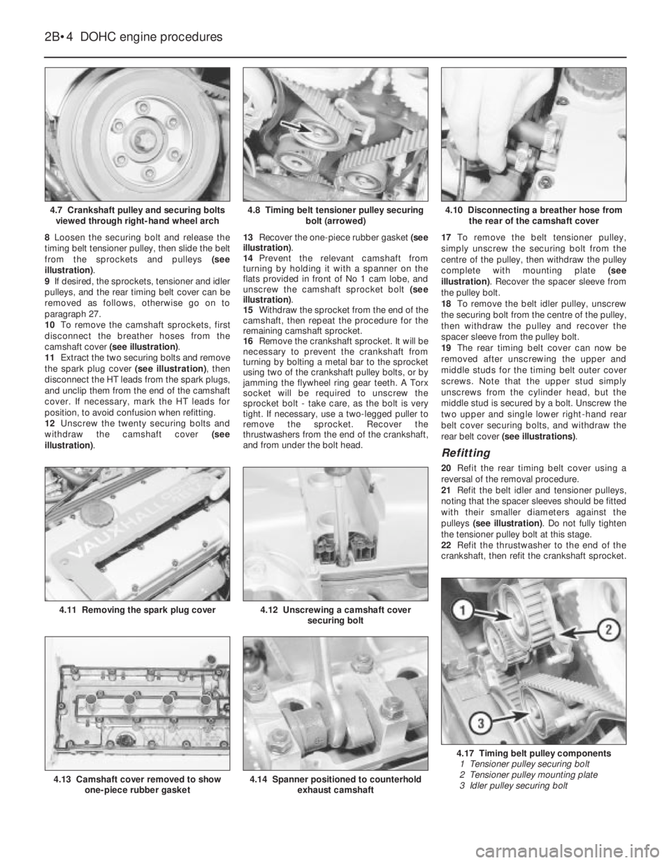
8Loosen the securing bolt and release the
timing belt tensioner pulley, then slide the belt
from the sprockets and pulleys (see
illustration).
9If desired, the sprockets, tensioner and idler
pulleys, and the rear timing belt cover can be
removed as follows, otherwise go on to
paragraph 27.
10To remove the camshaft sprockets, first
disconnect the breather hoses from the
camshaft cover (see illustration).
11Extract the two securing bolts and remove
the spark plug cover (see illustration), then
disconnect the HT leads from the spark plugs,
and unclip them from the end of the camshaft
cover. If necessary, mark the HT leads for
position, to avoid confusion when refitting.
12Unscrew the twenty securing bolts and
withdraw the camshaft cover (see
illustration).13Recover the one-piece rubber gasket (see
illustration).
14Prevent the relevant camshaft from
turning by holding it with a spanner on the
flats provided in front of No 1 cam lobe, and
unscrew the camshaft sprocket bolt (see
illustration).
15Withdraw the sprocket from the end of the
camshaft, then repeat the procedure for the
remaining camshaft sprocket.
16Remove the crankshaft sprocket. It will be
necessary to prevent the crankshaft from
turning by bolting a metal bar to the sprocket
using two of the crankshaft pulley bolts, or by
jamming the flywheel ring gear teeth. A Torx
socket will be required to unscrew the
sprocket bolt -take care, as the bolt is very
tight. If necessary, use a two-legged puller to
remove the sprocket. Recover the
thrustwashers from the end of the crankshaft,
and from under the bolt head.17To remove the belt tensioner pulley,
simply unscrew the securing bolt from the
centre of the pulley, then withdraw the pulley
complete with mounting plate (see
illustration). Recover the spacer sleeve from
the pulley bolt.
18To remove the belt idler pulley, unscrew
the securing bolt from the centre of the pulley,
then withdraw the pulley and recover the
spacer sleeve from the pulley bolt.
19The rear timing belt cover can now be
removed after unscrewing the upper and
middle studs for the timing belt outer cover
screws. Note that the upper stud simply
unscrews from the cylinder head, but the
middle stud is secured by a bolt. Unscrew the
two upper and single lower right-hand rear
belt cover securing bolts, and withdraw the
rear belt cover (see illustrations).
Refitting
20Refit the rear timing belt cover using a
reversal of the removal procedure.
21Refit the belt idler and tensioner pulleys,
noting that the spacer sleeves should be fitted
with their smaller diameters against the
pulleys (see illustration). Do not fully tighten
the tensioner pulley bolt at this stage.
22Refit the thrustwasher to the end of the
crankshaft, then refit the crankshaft sprocket.
2B•4DOHC engine procedures
4.7 Crankshaft pulley and securing bolts
viewed through right-hand wheel arch4.10 Disconnecting a breather hose from
the rear of the camshaft cover
4.17 Timing belt pulley components
1 Tensioner pulley securing bolt
2 Tensioner pulley mounting plate
3 Idler pulley securing bolt
4.14 Spanner positioned to counterhold
exhaust camshaft4.13 Camshaft cover removed to show
one-piece rubber gasket
4.12 Unscrewing a camshaft cover
securing bolt4.11 Removing the spark plug cover
4.8 Timing belt tensioner pulley securing
bolt (arrowed)
Page 192 of 525

Apply a little grease to the threads of the
securing bolt, and tighten it to the specified
torque in the two stages given in the Specifi-
cations. Ensure that the thrustwasher is in
place under the bolt head, and prevent the
crankshaft from turning as during removal.
23Refit the camshaft sprockets. Ensure that
the locating pins on the ends of the camshafts
engage with the holes in the sprockets and
with the sprocket timing marks facing
forwards. Then tighten the securing bolts to
the specified torque in the two stages given in
the Specifications. Prevent the camshafts
from turning as during removal.
24Check the condition of the camshaft
cover rubber gasket and renew if necessary,
then refit the camshaft cover and tighten the
securing bolts (see illustration).
25Refit the HT leads to the spark plugs
(ensuring that they are refitted to their correct
cylinders), then clip the leads to the end of the
camshaft cover. Refit the spark plug cover
and tighten the securing bolts.
26Reconnect the breather hose to the
camshaft cover.
27Temporarily refit the crankshaft pulley,
and ensure that the crankshaft pulley and
camshaft sprocket timing marks are still
aligned as described in paragraph 6. Then fit a
new timing belt around the sprockets and
pulleys, starting at the crankshaft sprocket.
28Refit the crankshaft pulley, and tighten the
securing bolts to the specified torque. If
necessary, prevent the crankshaft from
turning as during removal. 29Adjust the timing belt tension, as
described from paragraph 35 onwards.
30Refit the outer timing belt cover, ensuring
that the rubber grommets are in place in the
screw holes, and tighten the securing screws.
31Refit the alternator drivebelt and adjust
the drivebelt tension, as described in Chapter
5.
32Refit the power steering pump drivebelt
and adjust the drivebelt tension, as described
in Chapter 10.
33Refit the air cleaner components as
applicable, referring to Chapter 4B, if
necessary.
34Reconnect the battery negative lead.
Adjustment
Note: The manufacturers specify the use of
special adjustment wrench Vauxhall tool No
KM-666 for adjusting the timing belt tension. If
access to this tool cannot be obtained an
approximate adjustment can be achieved
using the method described in this Section.
However it is emphasised that the vehicle
should be taken to a dealer at the earliest
possible opportunity to have the tension
adjusted using the special tool. Do not drive
the vehicle over any long distance until the
belt tension has been adjusted by a dealer
Approximate adjustment
35No checking of timing belt adjustment is
specified, and the following adjustment
procedure applies to a newly fitted belt. The
adjustment must be carried out with the
engine cold.36With the timing belt cover removed and
the tensioner pulley bolt slackened, ensure
that the TDC marks on the camshaft
sprockets and the crankshaft pulley are
aligned as described in paragraph 6. If
necessary, turn the crankshaft to achieve
alignment.
37Have an assistant press the tensioner
pulley against the belt until the belt can just be
twisted through 45°, using moderate pressure
with the thumb and forefinger, on the longest
belt run between the exhaust camshaft
sprocket and the belt idler pulley.
38Have the assistant hold the tensioner
pulley in position, and tighten the tensioner
pulley bolt to the specified torque in the two
stages given in the Specifications.
39Turn the crankshaft clockwise through
two complete revolutions, and check that,
with the crankshaft pulley TDC mark aligned
with the pointer on the rear timing belt cover,
the TDC marks on the camshaft sprockets are
still aligned with the notches in the camshaft
cover.
40Proceed as described in paragraphs 30 to
34, inclusive.
41Have the belt tension adjusted by a
Vauxhall dealer using the manufacturer’s
special tool at the earliest opportunity.Adjustment using Vauxhall special
tool (KM-666)
42Proceed as described in paragraphs 35
and 36.
43Fit the special tool KM-666 to the belt
tensioner pulley mounting plate, in
accordance with the tool manufacturer’s
instructions.
44Working anti-clockwise from the TDC
mark on the exhaust camshaft sprocket, mark
the seventh tooth on the sprocket (see
illustration).
45Turn the crankshaft clockwise until this
tooth is aligned with the TDC notch in the
camshaft cover. The crankshaft must be
turned evenly and without jerking, to prevent
the timing belt from jumping off the sprockets
and pulleys.
46Tighten the tensioner pulley bolt to the
specified torque in the two stages given in the
Specifications.
47Remove the special tool.
DOHC engine procedures 2B•5
4.21 Belt tensioner pulley and spacer
sleeve. Note that smaller diameter of
spacer sleeve fits against pulley
4.44 Working anti-clockwise from the TDC
mark on the exhaust camshaft sprocket,
mark the seventh tooth on the sprocket4.24 Tightening a camshaft cover securing
bolt
4.19B Rear timing belt cover lower right-
hand securing bolt4.19A Timing belt outer cover screw upper
stud (1) and rear belt cover upper
securing bolts (2)
2B
Page 194 of 525
pitting. If evident, the cylinder head and all
bearing caps must be renewed as a matched
set, as there is no provision for refacing if the
bearing caps cannot be renewed individually.
8The camshaft(s) should show no marks or
scoring on the journal or cam lobe surfaces. if
evident, renew the camshaft(s).
9It is advisable to renew the camshaft front
oil seal(s) as a matter of course. Prise the old
seal(s) from the front of the camshaft(s) and
discard them.
Refitting
10Begin refitting by liberally coating the
contact faces of the hydraulic valve lifters and
the camshaft(s) with molybdenum disulphide
paste.
11Coat the mating faces of the front and
rear bearing caps with sealing compound and
refit the bearing caps in their original positions
as noted during removal.
12Tighten the camshaft bearing cap nuts to
the specified torque in half-turn stages, as
when loosening the nuts. Note that when
refitting the exhaust camshaft, the two smaller
rear bearing cap securing nuts should be
tightened after all the main camshaft bearing
cap nuts have been tightened. Note also that
the two smaller nuts should be tightened to a
lower torque wrench setting than the main
nuts.
13Turn the camshaft until the locating peg
for the camshaft sprocket is uppermost, then
lubricate the lips of a rear camshaft front oil
seal with a little grease, and fit the oil seal,
using a tube or socket of similar diameter with
a washer and the camshaft sprocket bolt.
Screw the camshaft sprocket bolt into the end
of the camshaft to draw the oil seal into
position on its shoulder.
14Repeat the procedure for the remaining
camshaft.
15Refit the distributor with reference to
Chapter 5. Fit a new timing belt and the
camshaft sprockets, then adjust the timing
belt as described in Section 4 or 5, as
applicable.
8Cylinder head -removal and
refitting (engine in vehicle)
4
Note: The engine must be cold when the
cylinder head is removed. Do not remove the
cylinder head from a hot engine. New cylinder
head bolts, a new cylinder head gasket and a
new timing belt must be used on refitting.
The torque settings (as shown in Chapter 2A)
are only applicable to latest specification head
bolts, available from Vauxhall. Earlier type or
alternative make, head bolts may require
different torques. Consult your supplier
Removal
1Disconnect the battery negative lead.
2Drain the cooling system, as described in
Chapter 3.3Remove the front section of the exhaust
system, as described in Chapter 4C.
4The cylinder head can be removed
complete with the inlet manifold, or the inlet
manifold can be detached from the cylinder
head before removal, with reference to
Chapter 4B. If no work is to be carried out on
the inlet manifold, it can be unbolted from the
cylinder head and supported to one side out
of the way, thus avoiding the need to
disconnect the relevant hoses, pipes and
wiring.
5If the cylinder head is to be removed
complete with the inlet manifold, disconnect
all relevant hoses, pipes and wiring from the
inlet manifold and associated components,
referring to Chapter 4B, and unbolt the
manifold support bracket from the manifold.
Loosen the alternator mountings with
reference to Chapter 5, then unbolt the upper
alternator mounting from the inlet manifold.
6If the inlet manifold is to be left in the engine
compartment, continue as follows, otherwise
go on to paragraph 17.
7Disconnect the wiring plug from the airflow
meter, and the breather hose from the air box
on the throttle body. Disconnect the air
cleaner trunking and remove the airflow
meter/air box assembly from the throttle
body. Refer to Chapter 4B if necessary.
8Disconnect the end of the throttle cable
from the throttle valve lever, then unbolt the
throttle cable support bracket and remove it
from the inlet manifold.
9Unscrew the two earth lead securing nuts
from the fuel rail (one at each end of the rail)
and disconnect the three earth leads.
10Disconnect the wiring plug from the
throttle position switch.
11Pull up on the wiring harness housing, and
disconnect the wiring plugs from the fuel
injectors by compressing the retaining clips.
Move the wiring harness housing to one side.
12Disconnect the two breather hoses from
the rear of the camshaft cover.
13Loosen the alternator mountings, with
reference to Chapter 5, then unbolt the upper
alternator mounting from the inlet manifold.
14Unbolt the manifold support bracket from
the manifold.15Make a final check to ensure that all
necessary hoses, pipes and wires have been
disconnected, then unscrew the securing nuts
and lift the inlet manifold from the cylinder
head. Ensure that the manifold is properly
supported, taking care not to strain any of the
hoses, pipes and wires, etc., which are still
connected.
16Recover the manifold gasket from the
cylinder head.
17Remove the timing belt, camshaft
sprockets, and timing belt tensioner and idler
pulleys, as described in Section 4.
18Unscrew the upper and middle studs for
the timing belt outer cover screws. Note that
the upper stud simply unscrews from the
cylinder head, but the middle stud is secured
by a bolt.
19Unscrew the two upper rear timing belt
cover securing bolts from the cylinder head.
20Remove the distributor cap and HT leads
with reference to Chapter 5.
21Disconnect the distributor wiring plug.
22Disconnect the coolant hose from the
left-hand end of the cylinder head.
23Unscrew the bolt securing the crankcase
breather tube bracket to the end of the
cylinder head.
24Disconnect the radiator top hose from the
thermostat housing, and disconnect the
wiring plugs from the temperature gauge
sender and the coolant temperature sensor
(both situated in the thermostat housing).
25Make a final check to ensure that all
relevant hoses, pipes and wires have been
disconnected.
26On X20 XEV models, remove the
camshaft, as described in Section 7.
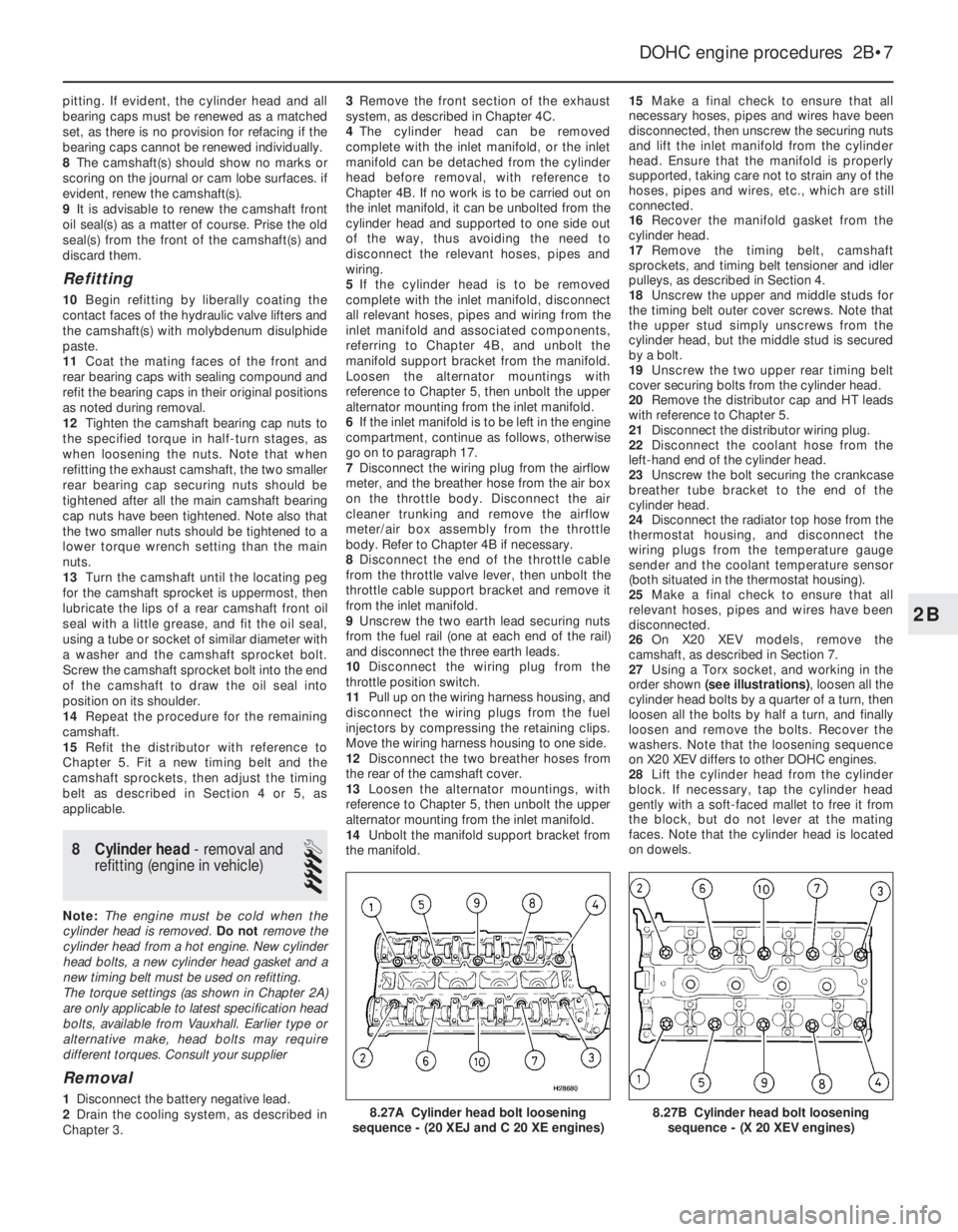
27Using a Torx socket, and working in the
order shown (see illustrations), loosen all the
cylinder head bolts by a quarter of a turn, then
loosen all the bolts by half a turn, and finally
loosen and remove the bolts. Recover the
washers. Note that the loosening sequence
on X20 XEV differs to other DOHC engines.
28Lift the cylinder head from the cylinder
block. If necessary, tap the cylinder head
gently with a soft-faced mallet to free it from
the block, but do not lever at the mating
faces. Note that the cylinder head is located
on dowels.
DOHC engine procedures 2B•7
8.27B Cylinder head bolt loosening
sequence - (X 20 XEV engines)8.27A Cylinder head bolt loosening
sequence - (20 XEJ and C 20 XE engines)
2B
Page 195 of 525
29Recover the cylinder head gasket and
discard it.
30Clean the cylinder head and block mating
faces by careful scraping. Take care not to
damage the cylinder head, which is made of
light alloy and is easily scored. Cover the
coolant passages and other openings with
masking tape or rag, to prevent dirt and
carbon falling in. Mop out all the oil from the
bolt holes; if oil is left in the holes, hydraulic
pressure could crack the block when the bolts
are refitted.
31If desired, the cylinder head can be
dismantled and inspected as described in
Section 10.
Refitting
32Begin refitting by locating a new gasket
on the block so that the word “OBEN” or
“TOP” is uppermost at the timing belt end of
the engine.
33With the mating faces scrupulously clean,
locate the cylinder head on the block so that
the positioning dowels engage in their holes.
34Temporarily refit the crankshaft pulley and
the camshaft sprockets, and ensure that the
timing marks are still positioned as they were
before the timing belt was removed (see
Section 4).35Fit the new cylinder head bolts, ensuring
that the washers are in place under their
heads, and screw the bolts in by hand as far
as possible.
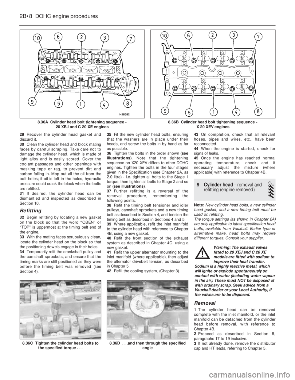
36Tighten the bolts in the order shown (see
illustrations). Note that the tightening
sequence on X20 XEV differs to other DOHC
engines. Tighten the bolts in the four stages
given in the Specification (see Chapter 2A, as
2.0 litre) - i.e. tighten all bolts to the Stage 1
torque, then tighten all bolts to Stage 2 and so
on (see illustrations).
37Further refitting is a reversal of the
removal procedure, remembering the
following points.
38Refit the timing belt tensioner and idler
pulleys, camshaft sprockets and a new timing
belt as described in Section 4, and tension the
timing belt as described in Sections 4 and 5.
39Where applicable, refit the inlet manifold
to the cylinder head with reference to Chapter
4B, using a new gasket.
40Refit the front section of the exhaust
system as described in Chapter 4C, using a
new gasket.
41Refit the upper alternator mounting to the
inlet manifold (where applicable), then adjust
the alternator drivebelt tension, as described
in Chapter 5.
42Refill the cooling system, (Chapter 3).43On completion, check that all relevant
hoses, pipes and wires, etc., have been
reconnected.
44When the engine is started, check for
signs of leaks.
45Once the engine has reached normal
operating temperature, check and if
necessary adjust the mixture (where
applicable) with reference to Chapter 4B.
9Cylinder head -removal and
refitting (engine removed)
4
Note: New cylinder head bolts, a new cylinder
head gasket, and a new timing belt must be
used on refitting.
The torque settings (as shown in Chapter 2A)
are only applicable to latest specification head
bolts, available from Vauxhall. Earlier type or
alternative make, head bolts may require
different torques. Consult your supplier.
Removal
1The cylinder head can be removed
complete with the inlet manifold, or the inlet
manifold can be detached from the cylinder
head before removal, with reference to
Chapter 4B.
2Proceed as described in Section 8,
paragraphs 17 to 19 inclusive.
3If not already done, remove the distributor
cap and HT leads, referring to Chapter 5.
2B•8DOHC engine procedures
8.36A Cylinder head bolt tightening sequence -
20 XEJ and C 20 XE engines
8.36C Tighten the cylinder head bolts to
the specified torque . . .8.36D . . .and then through the specified
angle
8.36B Cylinder head bolt tightening sequence -
X 20 XEV engines
Warning: The exhaust valves
fitted to 20 XEJ and C 20 XE
models are fitted with sodium to
improve their heat transfer.
Sodium is a highly reactive metal, which
will ignite or explode spontaneously on
contact with water (including water vapour
in the air). These must NOT be disposed of
with ordinary scrap. Seek advice from a
Vauxhall dealer or your Local Authority, if
the valves are to be disposed.