1988 OPEL CALIBRA drain bolt
[x] Cancel search: drain boltPage 12 of 525
Refitting
6On refitting the filter, press it into the union
until it catches (see illustration). The
remainder of the reassembly procedure is the
reverse of removal.
22Throttle valve dashpot
(automatic models) -
adjustment
2
1Remove the air cleaner or air box, refer to
Section 3.
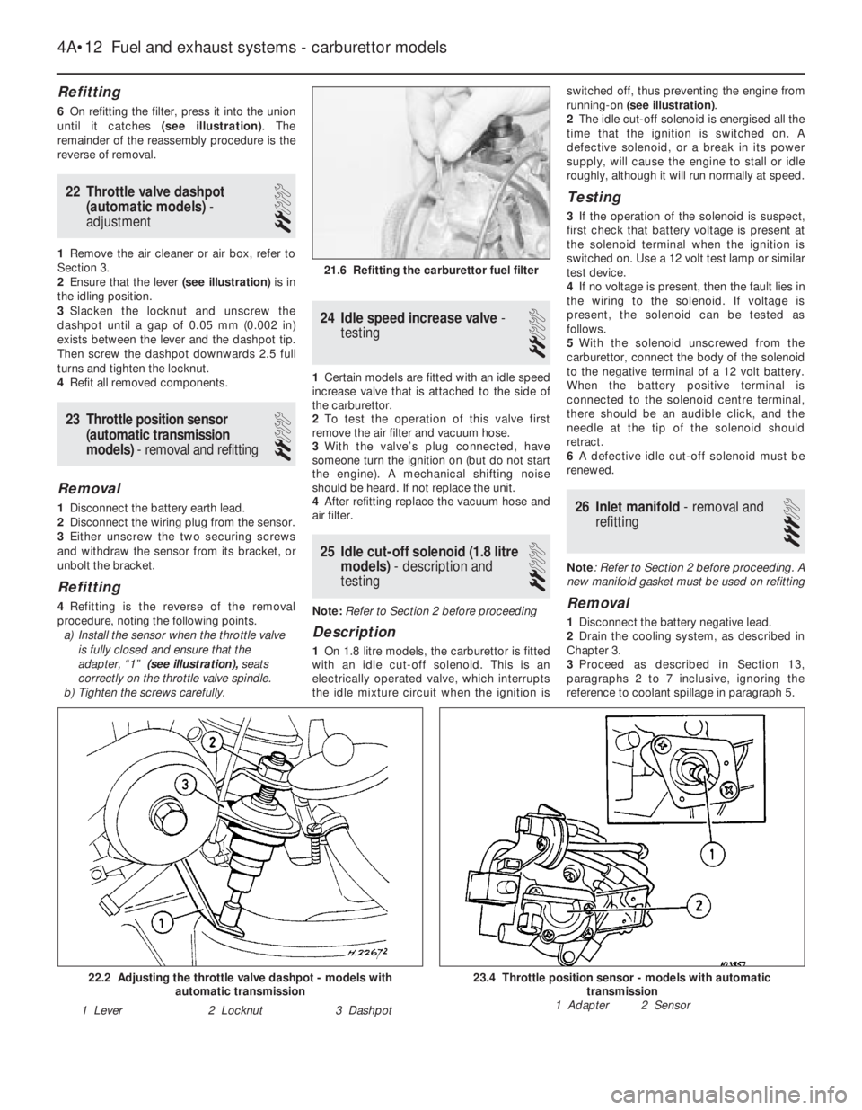
2Ensure that the lever (see illustration)is in
the idling position.
3Slacken the locknut and unscrew the
dashpot until a gap of 0.05 mm (0.002 in)
exists between the lever and the dashpot tip.
Then screw the dashpot downwards 2.5 full
turns and tighten the locknut.
4Refit all removed components.
23Throttle position sensor
(automatic transmission
models) - removal and refitting
2
Removal
1Disconnect the battery earth lead.
2Disconnect the wiring plug from the sensor.
3Either unscrew the two securing screws
and withdraw the sensor from its bracket, or
unbolt the bracket.
Refitting
4Refitting is the reverse of the removal
procedure, noting the following points.
a)Install the sensor when the throttle valve
is fully closed and ensure that the
adapter, “1” (see illustration),seats
correctly on the throttle valve spindle.
b)Tighten the screws carefully.
24Idle speed increase valve -
testing
2
1Certain models are fitted with an idle speed
increase valve that is attached to the side of
the carburettor.
2To test the operation of this valve first
remove the air filter and vacuum hose.
3With the valve’s plug connected, have
someone turn the ignition on (but do not start
the engine). A mechanical shifting noise
should be heard. If not replace the unit.
4After refitting replace the vacuum hose and
air filter.
25Idle cut-off solenoid (1.8 litre
models) - description and
testing
2
Note: Refer to Section 2 before proceeding
Description
1On 1.8 litre models, the carburettor is fitted
with an idle cut-off solenoid. This is an
electrically operated valve, which interrupts
the idle mixture circuit when the ignition isswitched off, thus preventing the engine from
running-on (see illustration).
2The idle cut-off solenoid is energised all the
time that the ignition is switched on. A
defective solenoid, or a break in its power
supply, will cause the engine to stall or idle
roughly, although it will run normally at speed.
Testing
3If the operation of the solenoid is suspect,
first check that battery voltage is present at
the solenoid terminal when the ignition is
switched on. Use a 12 volt test lamp or similar
test device.
4If no voltage is present, then the fault lies in
the wiring to the solenoid. If voltage is
present, the solenoid can be tested as
follows.
5With the solenoid unscrewed from the
carburettor, connect the body of the solenoid
to the negative terminal of a 12 volt battery.
When the battery positive terminal is
connected to the solenoid centre terminal,
there should be an audible click, and the
needle at the tip of the solenoid should
retract.
6A defective idle cut-off solenoid must be
renewed.
26Inlet manifold - removal and
refitting
3
Note: Refer to Section 2 before proceeding. A
new manifold gasket must be used on refitting
Removal
1Disconnect the battery negative lead.
2Drain the cooling system, as described in
Chapter 3.
3Proceed as described in Section 13,
paragraphs 2 to 7 inclusive, ignoring the
reference to coolant spillage in paragraph 5.
4A•12Fuel and exhaust systems - carburettor models
21.6 Refitting the carburettor fuel filter
23.4 Throttle position sensor - models with automatic
transmission
1 Adapter 2 Sensor22.2 Adjusting the throttle valve dashpot - models with
automatic transmission
1 Lever2 Locknut3 Dashpot
Page 102 of 525
3Lift up the edge of the windscreen cowl
panel for access to the sensor.
4Disconnect the sensor wiring plug, and the
vacuum pipe.
5Pull the pressure sensor upwards to release
it from its bracket, and withdraw it from the
vehicle.
Refitting
6Refitting is a reversal of removal. However,
on Multec models no fuel vapour trap is fitted.
It is therefore essential that the sensor
vacuum hose is routed so that it falls steadily
from the sensor to the throttle body. This
precaution prevents any fuel droplets being
trapped in the sensor or hose, and allows
them to drain into the inlet port.
Oil temperature sensor
Removal
7The sensor is screwed into the inlet
manifold side of the cylinder block, next to the
starter motor’s right-hand end.
8The sensor can be reached quite easily
from above, but if it is to be removed from
beneath, ensure that the handbrake is
applied, and that the vehicle is securely
supported on axle stands (see “Jacking and
Vehicle Support”).
9Disconnect the battery negative lead.
10Disconnect the sensor wiring plug.
11Using a spanner, unscrew the sensor and
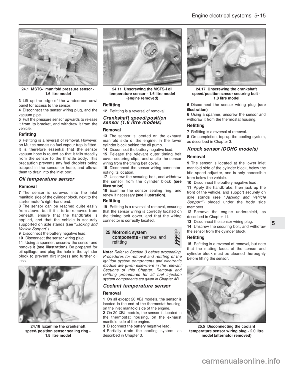
remove it (see illustration). Be prepared for
oil spillage, and plug the hole in the cylinder
block to prevent dirt ingress and further oil
loss.
Refitting
12Refitting is a reversal of removal.
Crankshaft speed/position
sensor (1.8 litre models)
Removal
13The sensor is located on the exhaust
manifold side of the engine, in the lower
cylinder block behind the oil pump.
14Disconnect the battery negative lead.
15Release the relevant outer timing belt
cover securing clips, and unclip the sensor
wiring from the timing belt cover.
16Disconnect the sensor wiring connector,
noting its location.
17Unscrew the securing bolt, and withdraw
the sensor from the cylinder block (see
illustration).
18Examine the sensor sealing ring, and
renew if necessary (see illustration).
Refitting
19Refitting is a reversal of removal, ensuring
that the sensor wiring is correctly located on
the timing belt cover, and that the wiring
connector is correctly located.
25Motronic system
components - removal and
refitting
3
Note: Refer to Section 3 before proceeding.
Procedures for removal and refitting of the
ignition system components and electronic
module are given elsewhere in the relevant
Sections of this Chapter. Removal and
refitting procedures for all fuel injection
system components are given in Chapter 4B
Coolant temperature sensor
Removal
1On all except 20 XEJ models, the sensor is
located in the end of the thermostat housing,
on the inlet manifold side of the engine.
2On 20 XEJ models, the sensor is located in
the thermostat housing, on the exhaust
manifold side of the engine.
3Disconnect the battery negative lead.
4Partially drain the cooling system, as
described in Chapter 3. 5Disconnect the sensor wiring plug (see
illustration).
6Using a spanner, unscrew the sensor and
withdraw it from the thermostat housing.
Refitting
7Refitting is a reversal of removal.
8On completion, top-up the cooling system,
as described in Chapter 3.
Knock sensor (DOHC models)
Removal
9The sensor is located at the lower inlet
manifold side of the cylinder block, below the
idle speed adjuster, and is only accessible
from below the vehicle.
10Disconnect the battery negative lead.
11Apply the handbrake, then jack up the
front of the vehicle, and support securely on
axle stands (see “Jacking and Vehicle
Support”) placed under the body side
members.
12Remove the engine undershield, as
described in Chapter 11.
13Disconnect the sensor wiring plug.
14Unscrew the securing bolt, and withdraw
the sensor from the cylinder block.
Refitting
15Refitting is a reversal of removal, but note
that the mating faces of the sensor and
cylinder block must be cleaned thoroughly
before fitting the sensor.
Engine electrical systems 5•15
24.17 Unscrewing the crankshaft
speed/position sensor securing bolt -
1.8 litre model
25.5 Disconnecting the coolant
temperature sensor wiring plug - 2.0 litre
model (alternator removed)24.18 Examine the crankshaft
speed/position sensor sealing ring -
1.8 litre model
24.11 Unscrewing the MSTS-i oil
temperature sensor - 1.6 litre model
(engine removed)24.1 MSTS-i manifold pressure sensor -
1.6 litre model
5
Page 171 of 525

12Unscrew and remove the top alternator
mounting nut and bolt.
13Make a final check to ensure that all
relevant hoses, pipes and wires have been
disconnected.
14Unscrew the securing nuts, and withdraw
the manifold from the cylinder head. Recover
the gasket (see illustrations).
15It is possible that some of the manifold
studs may be unscrewed from the cylinder
head when the manifold securing nuts are
unscrewed. In this event, the studs should be
screwed back into the cylinder head once the
manifold has been removed, using two
manifold nuts locked together.
16If desired, the ancillary components can
be removed from the manifold, referring to the
relevant Chapter.
Refitting
17Refitting is a reversal of removal,
remembering the following points.
18Where applicable refit any ancillary
components to the manifold, with reference to
relevant Sections of Chapters 4A or 4B.
19If the alternator mounting bracket has
been unbolted from the manifold, refit it
before refitting the manifold, as access to the
securing bolt is extremely limited once the
manifold is in place.
20Refit the manifold using a new gasket,
and tighten the securing nuts to the specified
torque.
21Ensure that all relevant hoses, pipes and
wires are correctly reconnected.
22On completion, check and if necessary
top-up the coolant level, (Chapter 3).
23Check and if necessary adjust the throttle
cable free play, as described in Chapters 4A
or 4B, as applicable.
24If any of the fuel system components have
been disturbed or renewed, check and if
necessary adjust the idle mixture, as
described in Chapters 4A or 4B, as applicable.
39Inlet manifold (SOHCwith
Multec) - removal and refitting
3
Removal
1Depressurise the fuel system Section 8).
2Remove the air box (see Section 5).
3Disconnect the battery negative lead.
4Either remove the throttle body assembly
(see Section 32), or disconnect the throttle
cable, wiring, fuel and vacuum hoses and
pipes to allow the manifold to be removed
with the throttle body.
5Drain the cooling system (see Chapter 3).
6Continue as described in Chapter 4A,
Section 26, paragraph 4 onwards.
Refitting
7Refitting is the reverse of the removal
procedure; renew all gaskets and seals
disturbed.
40Inlet manifold (DOHC
models) - removal and
refitting
3
Removal
1Disconnect the battery negative lead.
2Disconnect the wiring plug from the air
mass meter. Recover the sealing ring.
3Loosen the clamp screw securing the air
trunking to the right-hand end of the air mass
meter.
4Using an Allen key or hexagon bit, unscrew
the four bolts securing the air box to the
throttle body. Lift the air box from the throttle
body, and disconnect the hose from the base
of the air box then withdraw the air box/air
mass meter assembly.
5Disconnect the wiring plug from the throttle
position sensor.
6Slide the throttle cable end from the throttle
valve lever. Then pull the cable end grommet
from the bracket on the inlet manifold and
move the throttle cable to one side out of the
way.
7Disconnect the two breather hoses from the
rear of the camshaft cover. Disconnect the
larger hose from the throttle body, and
remove the hose completely.
8Position a wad of rag beneath one of the
fuel hose unions on the fuel rail, to absorb the
fuel that will be released as the union is
disconnected.
9Slowly loosen the fuel hose union, to
gradually relieve the pressure in the fuel feed
line, then disconnect the hose from the fuel
rail. Be prepared for fuel spillage, and take
adequate fire precautions. Plug the end of the
fuel hose, to prevent dirt ingress and further
fuel leakage.
10Repeat paragraphs 9 and 10 for the
remaining fuel hose-to-fuel rail union.
11Disconnect the vacuum pipe from the top
of the fuel pressure regulator.
12Disconnect the wiring harness housing
from the fuel injectors and move it to one side,
taking care not to strain the wiring. Pull up on
the wiring harness housing, and compress the
wiring plug retaining clips to release the
housing from the injectors.
13Unscrew the union nut, and disconnectthe brake servo vacuum hose from the left-
hand side of the inlet manifold (see
illustration).
14Unscrew the retaining nut, and remove
the fuel hose bracket from the left-hand side
of the throttle body.
15Unscrew the securing nuts, and
disconnect the earth leads from the fuel rail
securing studs at either end of the fuel rail.
16Unscrew the securing bolt, and remove
the cable/hose bracket from the left-hand end
of the inlet manifold.
17Remove the idle speed adjuster, as
described in Section 22.
18Unscrew and remove the top alternator
mounting nut and bolt.
19Make a final check to ensure that all
relevant hoses, pipes and wires have been
disconnected.
20Unscrew the securing nuts, and withdraw
the manifold from the cylinder head. Recover
the gasket.
21It is possible that some of the manifold
studs may be unscrewed from the cylinder
head when the manifold securing nuts are
unscrewed. In this event, the studs should be
screwed back into the cylinder head once the
manifold has been removed, using two
manifold nuts locked together.
22If desired, the ancillary components can
be removed from the manifold, with reference
to the relevant Sections of Chapters 4A or 4B.
Refitting
23Refitting is a reversal of the removal
procedure.
4B•18Fuel and exhaust systems - fuel injection models
38.14A Unscrew the securing nuts
40.13 Brake servo vacuum hose
connection at inlet manifold (arrowed) -
DOHC models
38.14B ...and withdraw the inlet manifold -
SOHC models
Page 180 of 525
test (refer to Chapter 2A) will provide valuable
information regarding the overall performance
of the main internal components. Such a test
can be used as a basis to decide on the
extent of the work to be carried out. If, for
example, a compression test indicates serious
internal engine wear, conventional
maintenance as described in this Chapter will
not greatly improve the performance of the
engine. It may also prove a waste of time and
money, unless extensive overhaul work is
carried out first.
The following series of operations are those
most often required to improve the
performance of a generally poor-running
engine:Primary operations
a)Clean, inspect and test the battery (See
“Weekly Checks”)
b)Check all the engine related fluids (See
“Weekly Checks”)
c)Check the condition and tension of the
auxiliary drivebelt (Sections 18 and 22, as
appropriate).
d)Renew the spark plugs (Sections 30 and
37, as appropriate).
e)Inspect the distributor cap, rotor arm and
HT leads, as applicable (Section 31).
f)Check the condition of the air filter, and
renew if necessary (Section 27).
g)Check the fuel filter (Section 29).
h)Check the condition of all hoses, and
check for fluid leaks (Section 4).i)Check the idle speed and mixture
settings, as applicable (Section 9).
5If the above operations do not prove fully
effective, carry out the following secondary
operations:
Secondary operations
All items listed under “Primary operations”,
plus the following:
a)Check the charging system (Chapter 5).
b)Check the ignition system (Chapter 5).
c)Check the fuel system (Chapters 4A and
4B).
d)Renew the distributor cap and rotor arm
(Section 31).
e)Renew the ignition HT leads (Section 31).
3Engine oil and filter - renewal
2
1Ideally, the oil should be drained with the
engine hot, just after the vehicle has been
driven.
2On DOHC models, remove the engine
undershield to expose the sump drain plug
and the oil filter.
3Place a container beneath the oil drain plug
at the rear of the sump.
4Remove the oil filler cap from the camshaft
cover, then using a socket or spanner,
unscrew the oil drain plug, and allow the oil to
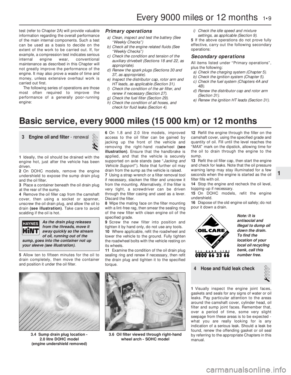
drain (see illustration). Take care to avoid
scalding if the oil is hot.
5Allow ten to fifteen minutes for the oil to
drain completely, then move the container
and position it under the oil filter.6On 1.8 and 2.0 litre models, improved
access to the oil filter can be gained by
jacking up the front of the vehicle and
removing the right-hand roadwheel (see
illustration). Ensure that the handbrake is
applied, and that the vehicle is securely
supported on axle stands (see “Jacking and
Vehicle Support”). Note that further oil may
drain from the sump as the vehicle is raised.
7Using a strap wrench or a filter removal tool
if necessary, slacken the filter and unscrew it
from the mounting. Alternatively, if the filter is
very tight, a screwdriver can be driven
through the filter casing and used as a lever.
Discard the filter.
8Wipe the mating face on the filter mounting
with a lint-free rag, then smear the sealing ring
of the new filter with clean engine oil of the
specified grade.
9Screw the new filter into position and
tighten it by hand only, do not use any tools.
10Where applicable, refit the roadwheel and
lower the vehicle to the ground. Fully tighten
the roadwheel bolts with the vehicle resting on
its wheels.
11Examine the condition of the oil drain plug
sealing ring and renew if necessary, then refit
the drain plug and tighten it to the specified
torque. 12Refill the engine through the filler on the
camshaft cover, using the specified grade and
quantity of oil. Fill until the level reaches the
“MAX” mark on the dipstick, allowing time for
the oil to drain through the engine to the
sump.
13Refit the oil filler cap, then start the engine
and check for leaks. Note that the oil pressure
warning lamp may stay illuminated for a few
seconds when the engine is started as the oil
filter fills with oil.
14Stop the engine and recheck the oil level,
topping-up if necessary.
15On DOHC models, refit the engine
undershield.
16Dispose of the old engine oil safely; do not
pour it down a drain.
4Hose and fluid leak check
1
1Visually inspect the engine joint faces,
gaskets and seals for any signs of water or oil
leaks. Pay particular attention to the areas
around the camshaft cover, cylinder head, oil
filter and sump joint faces. Remember that,
over a period of time, some very slight
seepage from these areas is to be expected -
what you are really looking for is any
indication of a serious leak. Should a leak be
found, renew the offending gasket or oil seal
by referring to the appropriate Chapters in this
manual.
Every 9000 miles or 12 months 1•9
3.6 Oil filter viewed through right-hand
wheel arch - SOHC model3.4 Sump drain plug location -
2.0 litre DOHC model
(engine undershield removed)
1
Basic service, every 9000 miles (15 000 km) or 12 months
As the drain plug releases
from the threads, move it
away quickly so the stream
of oil, running out of the
sump, goes into the container not up
your sleeve (see illustration).
Note: It is
antisocial and
illegal to dump oil
down the drain.
To find the
location of your
local oil recycling
bank, call this
number free.
Page 194 of 525
pitting. If evident, the cylinder head and all
bearing caps must be renewed as a matched
set, as there is no provision for refacing if the
bearing caps cannot be renewed individually.
8The camshaft(s) should show no marks or
scoring on the journal or cam lobe surfaces. if
evident, renew the camshaft(s).
9It is advisable to renew the camshaft front
oil seal(s) as a matter of course. Prise the old
seal(s) from the front of the camshaft(s) and
discard them.
Refitting
10Begin refitting by liberally coating the
contact faces of the hydraulic valve lifters and
the camshaft(s) with molybdenum disulphide
paste.
11Coat the mating faces of the front and
rear bearing caps with sealing compound and
refit the bearing caps in their original positions
as noted during removal.
12Tighten the camshaft bearing cap nuts to
the specified torque in half-turn stages, as
when loosening the nuts. Note that when
refitting the exhaust camshaft, the two smaller
rear bearing cap securing nuts should be
tightened after all the main camshaft bearing
cap nuts have been tightened. Note also that
the two smaller nuts should be tightened to a
lower torque wrench setting than the main
nuts.
13Turn the camshaft until the locating peg
for the camshaft sprocket is uppermost, then
lubricate the lips of a rear camshaft front oil
seal with a little grease, and fit the oil seal,
using a tube or socket of similar diameter with
a washer and the camshaft sprocket bolt.
Screw the camshaft sprocket bolt into the end
of the camshaft to draw the oil seal into
position on its shoulder.
14Repeat the procedure for the remaining
camshaft.
15Refit the distributor with reference to
Chapter 5. Fit a new timing belt and the
camshaft sprockets, then adjust the timing
belt as described in Section 4 or 5, as
applicable.
8Cylinder head -removal and
refitting (engine in vehicle)
4
Note: The engine must be cold when the
cylinder head is removed. Do not remove the
cylinder head from a hot engine. New cylinder
head bolts, a new cylinder head gasket and a
new timing belt must be used on refitting.
The torque settings (as shown in Chapter 2A)
are only applicable to latest specification head
bolts, available from Vauxhall. Earlier type or
alternative make, head bolts may require
different torques. Consult your supplier
Removal
1Disconnect the battery negative lead.
2Drain the cooling system, as described in
Chapter 3.3Remove the front section of the exhaust
system, as described in Chapter 4C.
4The cylinder head can be removed
complete with the inlet manifold, or the inlet
manifold can be detached from the cylinder
head before removal, with reference to
Chapter 4B. If no work is to be carried out on
the inlet manifold, it can be unbolted from the
cylinder head and supported to one side out
of the way, thus avoiding the need to
disconnect the relevant hoses, pipes and
wiring.
5If the cylinder head is to be removed
complete with the inlet manifold, disconnect
all relevant hoses, pipes and wiring from the
inlet manifold and associated components,
referring to Chapter 4B, and unbolt the
manifold support bracket from the manifold.
Loosen the alternator mountings with
reference to Chapter 5, then unbolt the upper
alternator mounting from the inlet manifold.
6If the inlet manifold is to be left in the engine
compartment, continue as follows, otherwise
go on to paragraph 17.
7Disconnect the wiring plug from the airflow
meter, and the breather hose from the air box
on the throttle body. Disconnect the air
cleaner trunking and remove the airflow
meter/air box assembly from the throttle
body. Refer to Chapter 4B if necessary.
8Disconnect the end of the throttle cable
from the throttle valve lever, then unbolt the
throttle cable support bracket and remove it
from the inlet manifold.
9Unscrew the two earth lead securing nuts
from the fuel rail (one at each end of the rail)
and disconnect the three earth leads.
10Disconnect the wiring plug from the
throttle position switch.
11Pull up on the wiring harness housing, and
disconnect the wiring plugs from the fuel
injectors by compressing the retaining clips.
Move the wiring harness housing to one side.
12Disconnect the two breather hoses from
the rear of the camshaft cover.
13Loosen the alternator mountings, with
reference to Chapter 5, then unbolt the upper
alternator mounting from the inlet manifold.
14Unbolt the manifold support bracket from
the manifold.15Make a final check to ensure that all
necessary hoses, pipes and wires have been
disconnected, then unscrew the securing nuts
and lift the inlet manifold from the cylinder
head. Ensure that the manifold is properly
supported, taking care not to strain any of the
hoses, pipes and wires, etc., which are still
connected.
16Recover the manifold gasket from the
cylinder head.
17Remove the timing belt, camshaft
sprockets, and timing belt tensioner and idler
pulleys, as described in Section 4.
18Unscrew the upper and middle studs for
the timing belt outer cover screws. Note that
the upper stud simply unscrews from the
cylinder head, but the middle stud is secured
by a bolt.
19Unscrew the two upper rear timing belt
cover securing bolts from the cylinder head.
20Remove the distributor cap and HT leads
with reference to Chapter 5.
21Disconnect the distributor wiring plug.
22Disconnect the coolant hose from the
left-hand end of the cylinder head.
23Unscrew the bolt securing the crankcase
breather tube bracket to the end of the
cylinder head.
24Disconnect the radiator top hose from the
thermostat housing, and disconnect the
wiring plugs from the temperature gauge
sender and the coolant temperature sensor
(both situated in the thermostat housing).
25Make a final check to ensure that all
relevant hoses, pipes and wires have been
disconnected.
26On X20 XEV models, remove the
camshaft, as described in Section 7.
27Using a Torx socket, and working in the
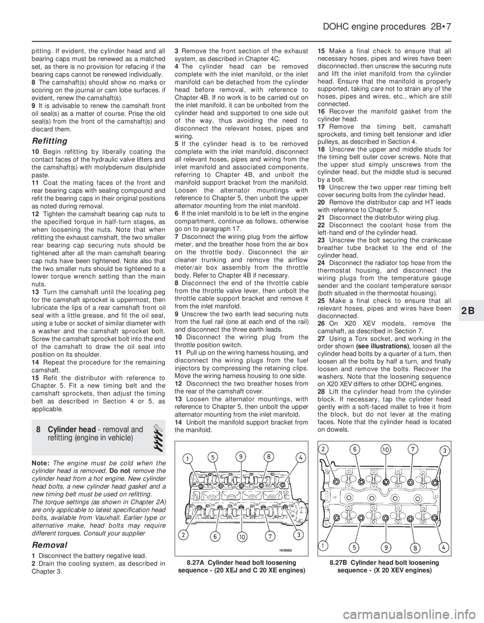
order shown (see illustrations), loosen all the
cylinder head bolts by a quarter of a turn, then
loosen all the bolts by half a turn, and finally
loosen and remove the bolts. Recover the
washers. Note that the loosening sequence
on X20 XEV differs to other DOHC engines.
28Lift the cylinder head from the cylinder
block. If necessary, tap the cylinder head
gently with a soft-faced mallet to free it from
the block, but do not lever at the mating
faces. Note that the cylinder head is located
on dowels.
DOHC engine procedures 2B•7
8.27B Cylinder head bolt loosening
sequence - (X 20 XEV engines)8.27A Cylinder head bolt loosening
sequence - (20 XEJ and C 20 XE engines)
2B
Page 205 of 525
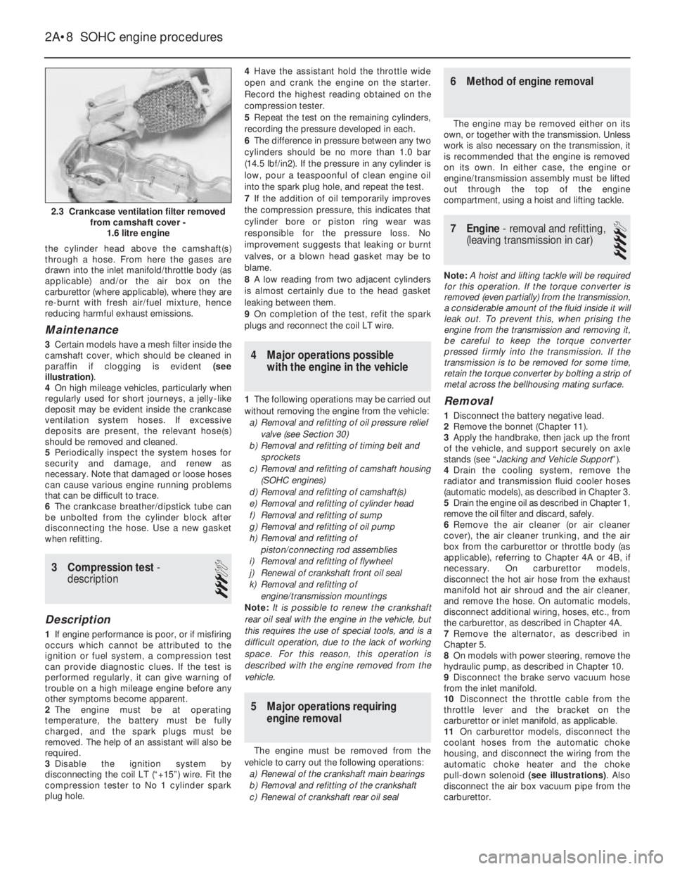
the cylinder head above the camshaft(s)
through a hose. From here the gases are
drawn into the inlet manifold/throttle body (as
applicable) and/or the air box on the
carburettor (where applicable), where they are
re-burnt with fresh air/fuel mixture, hence
reducing harmful exhaust emissions.
Maintenance
3Certain models have a mesh filter inside the
camshaft cover, which should be cleaned in
paraffin if clogging is evident (see
illustration).
4On high mileage vehicles, particularly when
regularly used for short journeys, a jelly-like
deposit may be evident inside the crankcase
ventilation system hoses. If excessive
deposits are present, the relevant hose(s)
should be removed and cleaned.
5Periodically inspect the system hoses for
security and damage, and renew as
necessary. Note that damaged or loose hoses
can cause various engine running problems
that can be difficult to trace.
6The crankcase breather/dipstick tube can
be unbolted from the cylinder block after
disconnecting the hose. Use a new gasket
when refitting.
3Compression test -
description
3
Description
1If engine performance is poor, or if misfiring
occurs which cannot be attributed to the
ignition or fuel system, a compression test
can provide diagnostic clues. If the test is
performed regularly, it can give warning of
trouble on a high mileage engine before any
other symptoms become apparent.
2The engine must be at operating
temperature, the battery must be fully
charged, and the spark plugs must be
removed. The help of an assistant will also be
required.
3Disable the ignition system by
disconnecting the coil LT (“+15”) wire. Fit the
compression tester to No 1 cylinder spark
plug hole.4Have the assistant hold the throttle wide
open and crank the engine on the starter.
Record the highest reading obtained on the
compression tester.
5Repeat the test on the remaining cylinders,
recording the pressure developed in each.
6The difference in pressure between any two
cylinders should be no more than 1.0 bar
(14.5 lbf/in2). If the pressure in any cylinder is
low, pour a teaspoonful of clean engine oil
into the spark plug hole, and repeat the test.
7If the addition of oil temporarily improves
the compression pressure, this indicates that
cylinder bore or piston ring wear was
responsible for the pressure loss. No
improvement suggests that leaking or burnt
valves, or a blown head gasket may be to
blame.
8A low reading from two adjacent cylinders
is almost certainly due to the head gasket
leaking between them.
9On completion of the test, refit the spark
plugs and reconnect the coil LT wire.
4Major operations possible
with the engine in the vehicle
1The following operations may be carried out
without removing the engine from the vehicle:
a)Removal and refitting of oil pressure relief
valve (see Section 30)
b)Removal and refitting of timing belt and
sprockets
c)Removal and refitting of camshaft housing
(SOHC engines)
d)Removal and refitting of camshaft(s)
e)Removal and refitting of cylinder head
f)Removal and refitting of sump
g)Removal and refitting of oil pump
h)Removal and refitting of
piston/connecting rod assemblies
i)Removal and refitting of flywheel
j)Renewal of crankshaft front oil seal
k)Removal and refitting of
engine/transmission mountings
Note: It is possible to renew the crankshaft
rear oil seal with the engine in the vehicle, but
this requires the use of special tools, and is a
difficult operation, due to the lack of working
space. For this reason, this operation is
described with the engine removed from the
vehicle.
5Major operations requiring
engine removal
The engine must be removed from the
vehicle to carry out the following operations:
a)Renewal of the crankshaft main bearings
b)Removal and refitting of the crankshaft
c)Renewal of crankshaft rear oil seal
6Method of engine removal
The engine may be removed either on its
own, or together with the transmission. Unless
work is also necessary on the transmission, it
is recommended that the engine is removed
on its own. In either case, the engine or
engine/transmission assembly must be lifted
out through the top of the engine
compartment, using a hoist and lifting tackle.
7Engine - removal and refitting,
(leaving transmission in car)
4
Note: A hoist and lifting tackle will be required
for this operation.If the torque converter is
removed (even partially) from the transmission,
a considerable amount of the fluid inside it will
leak out. To prevent this, when prising the
engine from the transmission and removing it,
be careful to keep the torque converter
pressed firmly into the transmission. If the
transmission is to be removed for some time,
retain the torque converter by bolting a strip of
metal across the bellhousing mating surface.
Removal
1Disconnect the battery negative lead.
2Remove the bonnet (Chapter 11).
3Apply the handbrake, then jack up the front
of the vehicle, and support securely on axle
stands (see “Jacking and Vehicle Support”).
4Drain the cooling system, remove the
radiator and transmission fluid cooler hoses
(automatic models), as described in Chapter 3.
5Drain the engine oil as described in Chapter 1,
remove the oil filter and discard, safely.
6Remove the air cleaner (or air cleaner
cover), the air cleaner trunking, and the air
box from the carburettor or throttle body (as
applicable), referring to Chapter 4A or 4B, if
necessary. On carburettor models,
disconnect the hot air hose from the exhaust
manifold hot air shroud and the air cleaner,
and remove the hose. On automatic models,
disconnect additional wiring, hoses, etc., from
the carburettor, as described in Chapter 4A.
7Remove the alternator, as described in
Chapter 5.
8On models with power steering, remove the
hydraulic pump, as described in Chapter 10.
9Disconnect the brake servo vacuum hose
from the inlet manifold.
10Disconnect the throttle cable from the
throttle lever and the bracket on the
carburettor or inlet manifold, as applicable.
11On carburettor models, disconnect the
coolant hoses from the automatic choke
housing, and disconnect the wiring from the
automatic choke heater and the choke
pull-down solenoid (see illustrations). Also
disconnect the air box vacuum pipe from the
carburettor.
2A•8SOHC engine procedures
2.3 Crankcase ventilation filter removed
from camshaft cover -
1.6 litre engine
Page 216 of 525
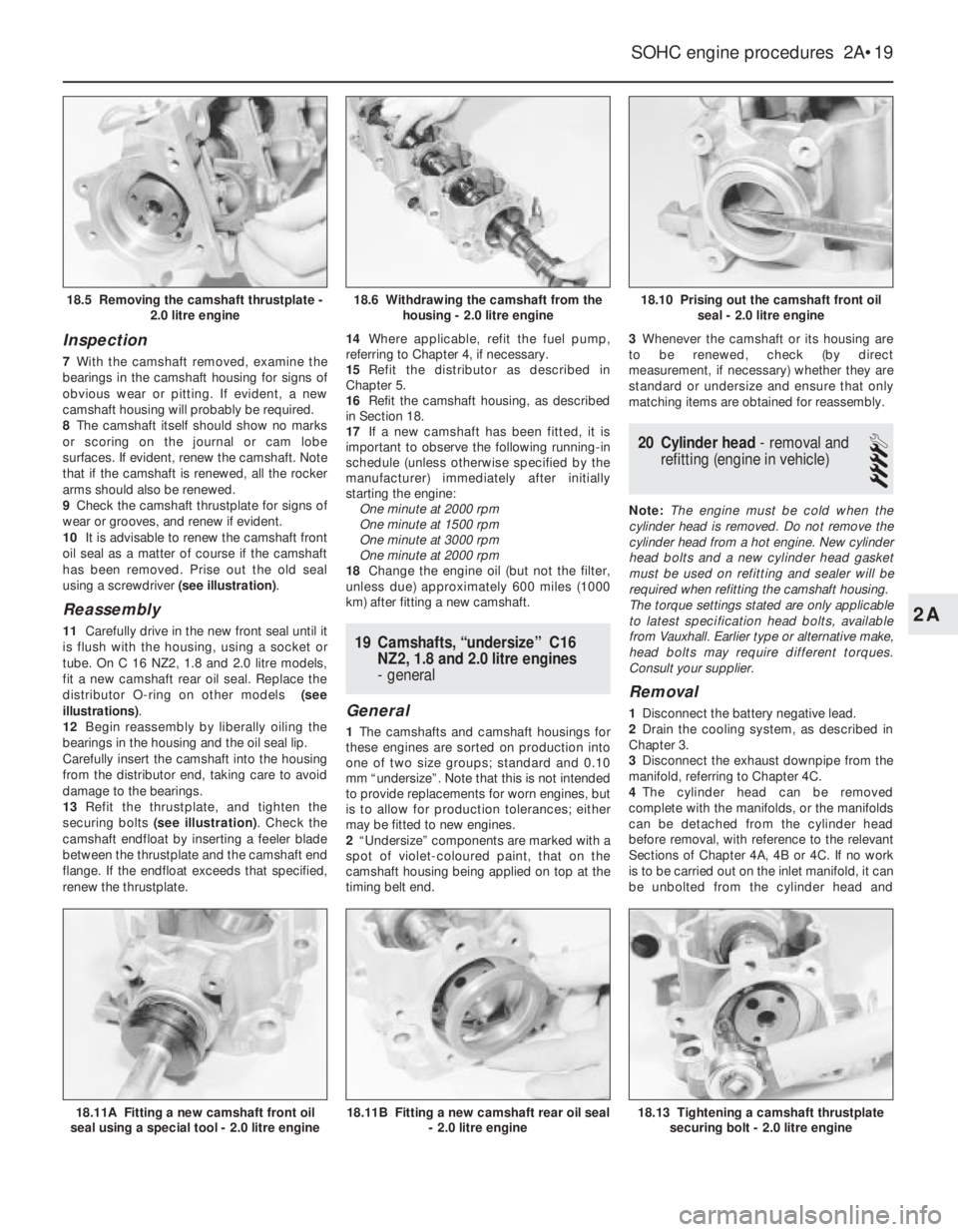
Inspection
7With the camshaft removed, examine the
bearings in the camshaft housing for signs of
obvious wear or pitting. If evident, a new
camshaft housing will probably be required.
8The camshaft itself should show no marks
or scoring on the journal or cam lobe
surfaces. If evident, renew the camshaft. Note
that if the camshaft is renewed, all the rocker
arms should also be renewed.
9Check the camshaft thrustplate for signs of
wear or grooves, and renew if evident.
10It is advisable to renew the camshaft front
oil seal as a matter of course if the camshaft
has been removed. Prise out the old seal
using a screwdriver (see illustration).
Reassembly
11Carefully drive in the new front seal until it
is flush with the housing, using a socket or
tube. On C 16 NZ2, 1.8 and 2.0 litre models,
fit a new camshaft rear oil seal. Replace the
distributor O-ring on other models (see
illustrations).
12Begin reassembly by liberally oiling the
bearings in the housing and the oil seal lip.
Carefully insert the camshaft into the housing
from the distributor end, taking care to avoid
damage to the bearings.
13Refit the thrustplate, and tighten the
securing bolts (see illustration). Check the
camshaft endfloat by inserting a feeler blade
between the thrustplate and the camshaft end
flange. If the endfloat exceeds that specified,
renew the thrustplate.14Where applicable, refit the fuel pump,
referring to Chapter 4, if necessary.
15Refit the distributor as described in
Chapter 5.
16Refit the camshaft housing, as described
in Section 18.
17If a new camshaft has been fitted, it is
important to observe the following running-in
schedule (unless otherwise specified by the
manufacturer) immediately after initially
starting the engine:
One minute at 2000 rpm
One minute at 1500 rpm
One minute at 3000 rpm
One minute at 2000 rpm
18Change the engine oil (but not the filter,
unless due) approximately 600 miles (1000
km) after fitting a new camshaft.19Camshafts, “undersize” C16
NZ2, 1.8 and 2.0 litre engines
- general
General
1The camshafts and camshaft housings for
these engines are sorted on production into
one of two size groups; standard and 0.10
mm “undersize”. Note that this is not intended
to provide replacements for worn engines, but
is to allow for production tolerances; either
may be fitted to new engines.
2“Undersize” components are marked with a
spot of violet-coloured paint, that on the
camshaft housing being applied on top at the
timing belt end.3Whenever the camshaft or its housing are
to be renewed, check (by direct
measurement, if necessary) whether they are
standard or undersize and ensure that only
matching items are obtained for reassembly.
20Cylinder head - removal and
refitting (engine in vehicle)
4
Note: The engine must be cold when the
cylinder head is removed. Do not remove the
cylinder head from a hot engine. New cylinder
head bolts and a new cylinder head gasket
must be used on refitting and sealer will be
required when refitting the camshaft housing.
The torque settings stated are only applicable
to latest specification head bolts, available
from Vauxhall. Earlier type or alternative make,
head bolts may require different torques.
Consult your supplier.
Removal
1Disconnect the battery negative lead.
2Drain the cooling system, as described in
Chapter 3.
3Disconnect the exhaust downpipe from the
manifold, referring to Chapter 4C.
4The cylinder head can be removed
complete with the manifolds, or the manifolds
can be detached from the cylinder head
before removal, with reference to the relevant
Sections of Chapter 4A, 4B or 4C. If no work
is to be carried out on the inlet manifold, it can
be unbolted from the cylinder head and
SOHC engine procedures 2A•19
18.10 Prising out the camshaft front oil
seal - 2.0 litre engine
18.13 Tightening a camshaft thrustplate
securing bolt - 2.0 litre engine18.11B Fitting a new camshaft rear oil seal
- 2.0 litre engine18.11A Fitting a new camshaft front oil
seal using a special tool - 2.0 litre engine
18.6 Withdrawing the camshaft from the
housing - 2.0 litre engine18.5 Removing the camshaft thrustplate -
2.0 litre engine
2A
Page 224 of 525
28Crankshaft rear oil seal -
renewal
4
Renewal
1With the engine removed from the vehicle,
remove the flywheel, or flexplate (as
applicable) as described in Sections 25 and
26.
2Punch or drill a small hole in the centre of
the now-exposed oil seal. Screw in a
self-tapping screw, and pull on the screw with
pliers to extract the seal. Several attempts
may be necessary. Be careful not to damage
the sealing face of the crankshaft.
3Clean the oil seal seat with a wooden or
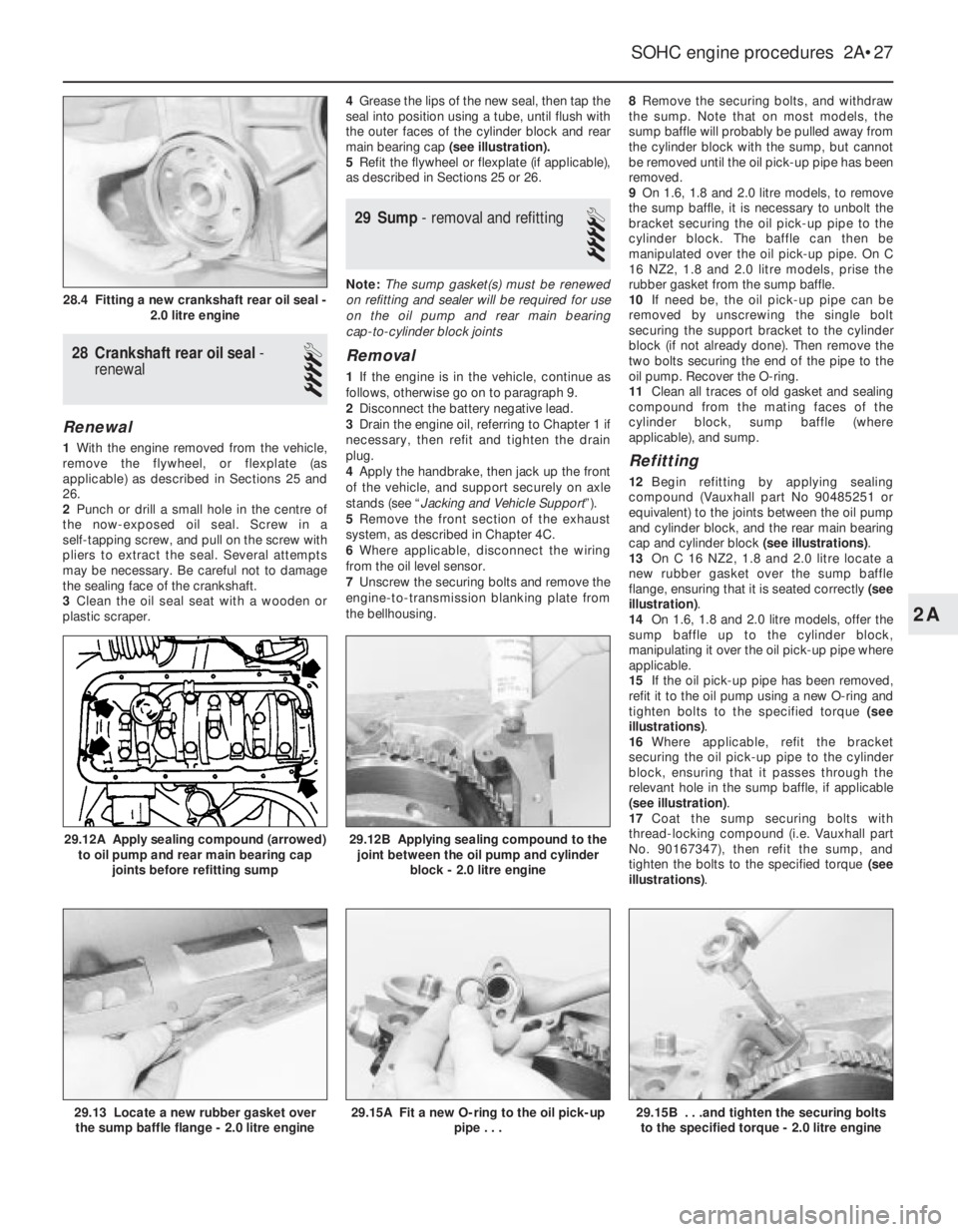
plastic scraper.4Grease the lips of the new seal, then tap the
seal into position using a tube, until flush with
the outer faces of the cylinder block and rear
main bearing cap (see illustration).
5Refit the flywheel or flexplate (if applicable),
as described in Sections 25 or 26.
29Sump - removal and refitting
4
Note: The sump gasket(s) must be renewed
on refitting and sealer will be required for use
on the oil pump and rear main bearing
cap-to-cylinder block joints
Removal
1If the engine is in the vehicle, continue as
follows, otherwise go on to paragraph 9.
2Disconnect the battery negative lead.
3Drain the engine oil, referring to Chapter 1 if
necessary, then refit and tighten the drain
plug.
4Apply the handbrake, then jack up the front
of the vehicle, and support securely on axle
stands (see “Jacking and Vehicle Support”).
5Remove the front section of the exhaust
system, as described in Chapter 4C.
6Where applicable, disconnect the wiring
from the oil level sensor.
7Unscrew the securing bolts and remove the
engine-to-transmission blanking plate from
the bellhousing.8Remove the securing bolts, and withdraw
the sump. Note that on most models, the
sump baffle will probably be pulled away from
the cylinder block with the sump, but cannot
be removed until the oil pick-up pipe has been
removed.
9On 1.6, 1.8 and 2.0 litre models, to remove
the sump baffle, it is necessary to unbolt the
bracket securing the oil pick-up pipe to the
cylinder block. The baffle can then be
manipulated over the oil pick-up pipe. On C
16 NZ2, 1.8 and 2.0 litre models, prise the
rubber gasket from the sump baffle.
10If need be, the oil pick-up pipe can be
removed by unscrewing the single bolt
securing the support bracket to the cylinder
block (if not already done). Then remove the
two bolts securing the end of the pipe to the
oil pump. Recover the O-ring.
11Clean all traces of old gasket and sealing
compound from the mating faces of the
cylinder block, sump baffle (where
applicable), and sump.
Refitting
12Begin refitting by applying sealing
compound (Vauxhall part No 90485251 or
equivalent) to the joints between the oil pump
and cylinder block, and the rear main bearing
cap and cylinder block (see illustrations).
13On C 16 NZ2, 1.8 and 2.0 litre locate a
new rubber gasket over the sump baffle
flange, ensuring that it is seated correctly (see
illustration).
14On 1.6, 1.8 and 2.0 litre models, offer the
sump baffle up to the cylinder block,
manipulating it over the oil pick-up pipe where
applicable.
15If the oil pick-up pipe has been removed,
refit it to the oil pump using a new O-ring and
tighten bolts to the specified torque (see
illustrations).
16Where applicable, refit the bracket
securing the oil pick-up pipe to the cylinder
block, ensuring that it passes through the
relevant hole in the sump baffle, if applicable
(see illustration).
17Coat the sump securing bolts with
thread-locking compound (i.e. Vauxhall part
No. 90167347), then refit the sump, and
tighten the bolts to the specified torque (see
illustrations).
SOHC engine procedures 2A•27
29.12B Applying sealing compound to the
joint between the oil pump and cylinder
block - 2.0 litre engine
29.15B . . .and tighten the securing bolts
to the specified torque - 2.0 litre engine29.15A Fit a new O-ring to the oil pick-up
pipe . . .29.13 Locate a new rubber gasket over
the sump baffle flange - 2.0 litre engine
29.12A Apply sealing compound (arrowed)
to oil pump and rear main bearing cap
joints before refitting sump
28.4 Fitting a new crankshaft rear oil seal -
2.0 litre engine
2A