1988 OPEL CALIBRA dimensions
[x] Cancel search: dimensionsPage 116 of 525
4Certain models may have additional
underbody shields and splashguards fitted,
which may be attached to the wheel arch liners.
32Engine undershield (DOHC
models) - removal and
refitting
2
Removal
1Apply the handbrake, then jack up the front
of the vehicle, and support on axle stands
(see “Jacking and Vehicle Support”).
2Extract the two securing screws, and
remove the oil filter access panel.
3Working around the edges of the splash
shield, remove the self tapping screws that
secure the shield to the body, noting that
some of the screws also secure the wheel
arch liners.
4With the help of an assistant, pull the shield
from the vehicle, and place it to one side to
avoid damage.
Refitting
5Refitting is a reversal of removal.
33Fuel filler flap -removal and
refitting
2
Removal
1Open the flap for access to the four screws
securing the flap to the rear wing.2Remove the securing screws, and withdraw
the flap.
Refitting
3Refitting is a reversal of removal.
34Sunroof components -
removal and refitting
4
Note:The sunroof is a complex piece of
equipment consisting of a large number of
components. It is strongly recommended that
the sunroof mechanism is not disturbed unless
necessary. If the sunroof mechanism is faulty, or
requires overhaul, consult a dealer for advice.
Glass panel
Removal
1Push the sunshade fully rearwards, and
open the glass panel halfway.
2Extract the four securing screws from the
front edge of the guide rail plastic surround,
and withdraw the surround down through the
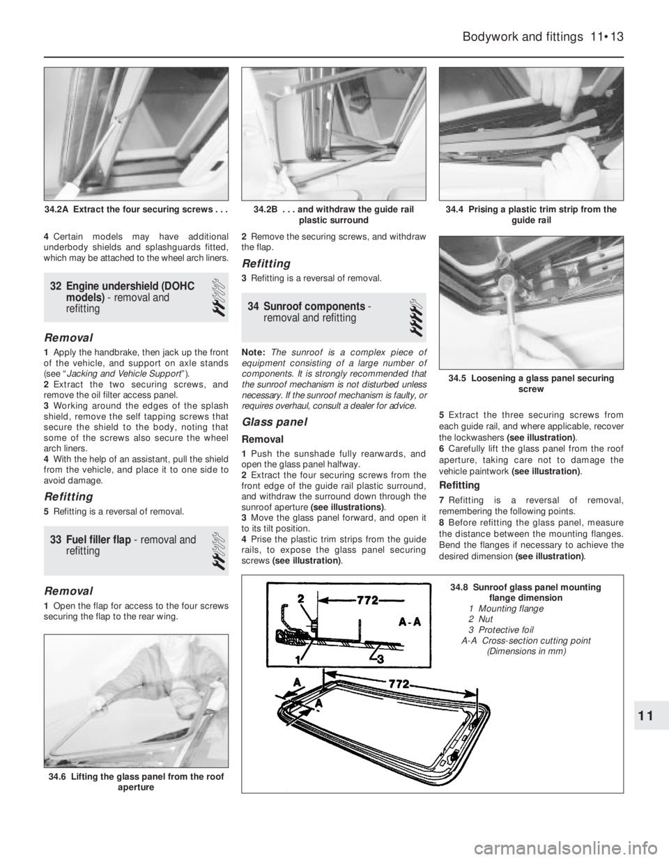
sunroof aperture (see illustrations).
3Move the glass panel forward, and open it
to its tilt position.
4Prise the plastic trim strips from the guide
rails, to expose the glass panel securing
screws (see illustration).5Extract the three securing screws from
each guide rail, and where applicable, recover
the lockwashers (see illustration).
6Carefully lift the glass panel from the roof
aperture, taking care not to damage the
vehicle paintwork (see illustration).
Refitting
7Refitting is a reversal of removal,
remembering the following points.
8Before refitting the glass panel, measure
the distance between the mounting flanges.
Bend the flanges if necessary to achieve the
desired dimension (see illustration).
Bodywork and fittings 11•13
34.4 Prising a plastic trim strip from the
guide rail
34.6 Lifting the glass panel from the roof
aperture
34.5 Loosening a glass panel securing
screw
34.2B . . . and withdraw the guide rail
plastic surround34.2A Extract the four securing screws . . .
11
34.8 Sunroof glass panel mounting
flange dimension
1 Mounting flange
2 Nut
3 Protective foil
A-A Cross-section cutting point
(Dimensions in mm)
Page 117 of 525
9Where applicable, ensure that the glass
panel securing screw lockwashers engage
with the locating pins on the guide rails.
10Before fully tightening the glass panel
securing screws, close the panel, and adjust
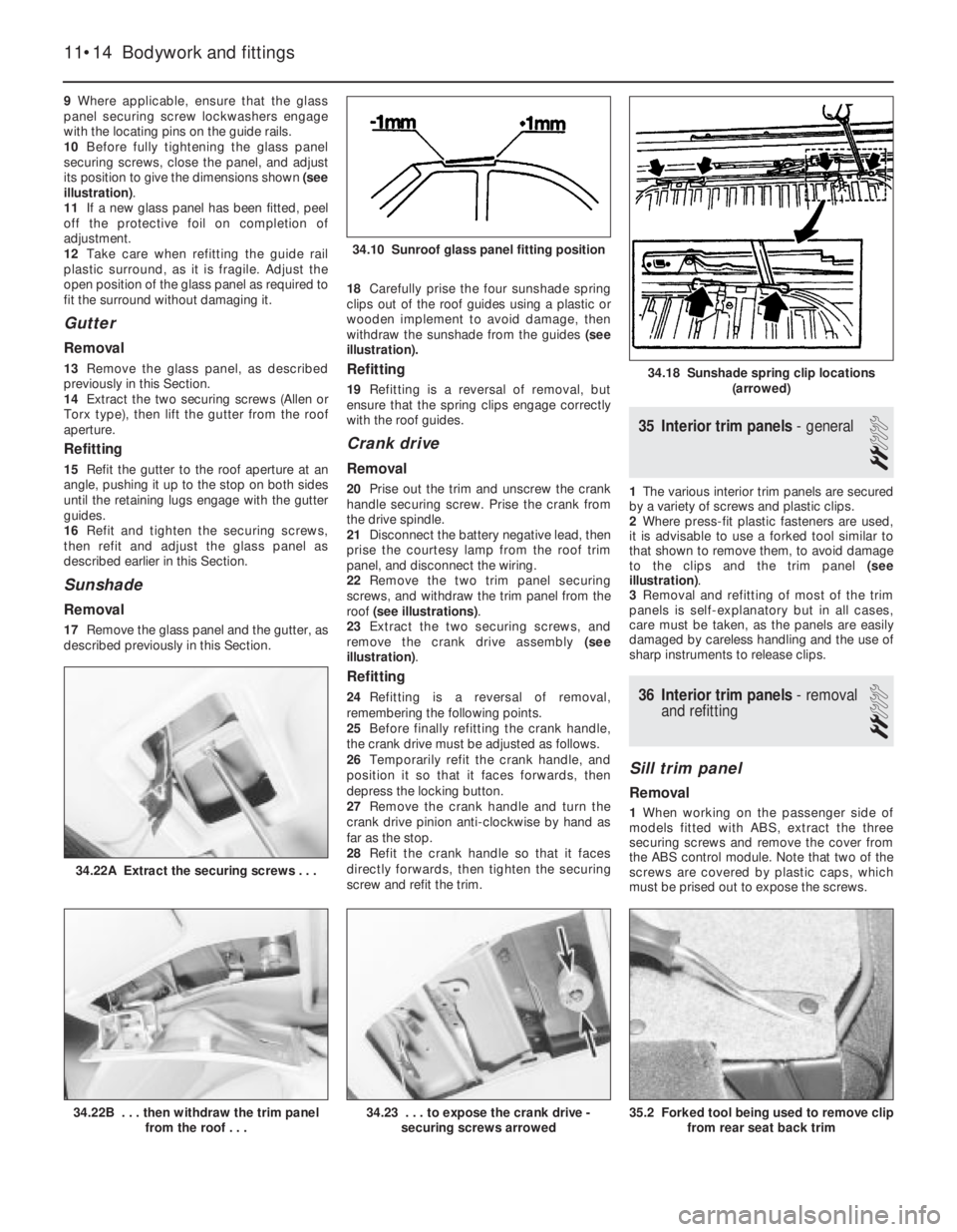
its position to give the dimensions shown (see
illustration).
11If a new glass panel has been fitted, peel
off the protective foil on completion of
adjustment.
12Take care when refitting the guide rail
plastic surround, as it is fragile. Adjust the
open position of the glass panel as required to
fit the surround without damaging it.
Gutter
Removal
13Remove the glass panel, as described
previously in this Section.
14Extract the two securing screws (Allen or
Torx type), then lift the gutter from the roof
aperture.
Refitting
15Refit the gutter to the roof aperture at an
angle, pushing it up to the stop on both sides
until the retaining lugs engage with the gutter
guides.
16Refit and tighten the securing screws,
then refit and adjust the glass panel as
described earlier in this Section.
Sunshade
Removal
17Remove the glass panel and the gutter, as
described previously in this Section. 18Carefully prise the four sunshade spring
clips out of the roof guides using a plastic or
wooden implement to avoid damage, then
withdraw the sunshade from the guides (see
illustration).
Refitting
19Refitting is a reversal of removal, but
ensure that the spring clips engage correctly
with the roof guides.
Crank drive
Removal
20Prise out the trim and unscrew the crank
handle securing screw. Prise the crank from
the drive spindle.
21Disconnect the battery negative lead, then
prise the courtesy lamp from the roof trim
panel, and disconnect the wiring.
22Remove the two trim panel securing
screws, and withdraw the trim panel from the
roof (see illustrations).
23Extract the two securing screws, and
remove the crank drive assembly (see
illustration).
Refitting
24Refitting is a reversal of removal,
remembering the following points.
25Before finally refitting the crank handle,
the crank drive must be adjusted as follows.
26Temporarily refit the crank handle, and
position it so that it faces forwards, then
depress the locking button.
27Remove the crank handle and turn the
crank drive pinion anti-clockwise by hand as
far as the stop.
28Refit the crank handle so that it faces
directly forwards, then tighten the securing
screw and refit the trim.
35Interior trim panels -general
2
1The various interior trim panels are secured
by a variety of screws and plastic clips.
2Where press-fit plastic fasteners are used,
it is advisable to use a forked tool similar to
that shown to remove them, to avoid damage
to the clips and the trim panel (see
illustration).
3Removal and refitting of most of the trim
panels is self-explanatory but in all cases,
care must be taken, as the panels are easily
damaged by careless handling and the use of
sharp instruments to release clips.
36Interior trim panels -removal
and refitting
2
Sill trim panel
Removal
1When working on the passenger side of
models fitted with ABS, extract the three
securing screws and remove the cover from
the ABS control module. Note that two of the
screws are covered by plastic caps, which
must be prised out to expose the screws.
11•14Bodywork and fittings
34.22A Extract the securing screws . . .
35.2 Forked tool being used to remove clip
from rear seat back trim34.23 . . . to expose the crank drive -
securing screws arrowed34.22B . . . then withdraw the trim panel
from the roof . . .
34.18 Sunshade spring clip locations
(arrowed)
34.10 Sunroof glass panel fitting position
Page 230 of 525

31Refit the previously removed
components, referring to the relevant
Sections of this Chapter.
35Crankshaft and bearings -
examination
4
Examination
1Examine the crankpin and main journal
surfaces for signs of scoring or scratches, and
check the ovality and taper of the crankpins
and main journals. If the bearing surface
dimensions do not fall within the tolerance
ranges given in the Specifications at the
beginning of this Chapter, the crankpins
and/or main journals will have to be reground.
2Big-end and crankpin wear is accompanied
by distinct metallic knocking, particularly
noticeable when the engine is pulling from low
revs, and some loss of oil pressure.
3Main bearing and main journal wear is
accompanied by severe engine vibration rumble
- getting progressively worse as engine rev’s
increase - and again by loss of oil pressure.
4If the crankshaft requires regrinding, take it
to an engine reconditioning specialist, who
will machine it for you and supply the correct
undersize bearing shells.
5Inspect the big-end and main bearing shells
for signs of general wear, scoring, pitting and
scratches. The bearings should be matt grey
in colour. With leadindium bearings, should a
trace of copper colour be noticed, the
bearings are badly worn, as the lead bearing
material has worn away to expose the indium
underlay. Renew the bearings if they are in
this condition, or if there are any signs of
scoring or pitting. You are strongly advised
to renew the bearings - regardless of their
condition at time of major overhaul.
Refitting used bearings is a false economy.
6The undersizes available are designed to
correspond with crankshaft regrind sizes. Thebearings are in fact, slightly more than the
stated undersize, as running clearances have
been allowed for during their manufacture.
7Main and big-end bearing shells can be
identified as to size by the marking on the
back of the shell. Standard size shell bearings
are marked STD or .00, undersize shells are
marked with the undersize such as 0.020 u/s.
This marking method applies only to
replacement bearing shells, and not to those
used during production.
8An accurate method of determining bearing
wear is by using a Plastigage. The crankshaft
is located in the main bearings (and, if
necessary, the big-end bearings), and the
Plastigage filament is located across the
journal. Vauxhall recommend that the
crankshaft journal and bearing shells are
lightly lubricated, to prevent the Plastigage
from tearing as the bearing cap is removed.
The bearing cap should be fitted, and the
bolts tightened to the specified torque. The
cap is then removed, and the width of the
filament is checked against a scale that shows
the bearing running clearance. The clearance
should be compared with that given in the
Specifications.
9Where applicable, check the teeth of the
crankshaft TDC sensor wheel for damage
(see illustration). If evident, the crankshaft
must be renewed.
10Similarly, check the condition of the pins
in the front crankshaft balance weight, which
serve as detect points for the plug-in
diagnostic sensor used by Vauxhall dealers
(see illustration).
36Cylinder block and bores -
examination and renovation
4
Examination
1Examine the cylinder bores for taper,
ovality, scoring and scratches. Start bycarefully examining the top of the cylinder
bores. If they are at all worn, a very slight
ridge will be found on the thrust side. This
marks the top of the piston ring travel. The
owner will have a good indication of the bore
wear before dismantling the engine, or
removing the cylinder head. Excessive oil
consumption, accompanied by blue smoke
from the exhaust, is a sure sign of worn
cylinder bores and piston rings.
2Measure the bore diameter across the
block, and just below any ridge. This can be
done with an internal micrometer or a dial
gauge. Compare this with the diameter of the
bottom of the bore, which is not subject to
wear. If no measuring instruments are
available, use a piston from which the rings
have been removed, and measure the gap
between it and the cylinder wall with a feeler
blade. Refer to the Specifications. If the
cylinder wear exceeds the permitted
tolerances, then the cylinders will need
reboring, in which case note the following
points:
a)Piston and cylinder bores are closely
matched in production. The actual
diameter of the piston is indicated by
numbers on its crown; the same numbers
stamped on the crankcase indicate the
bore diameter
b)After reboring has taken place, the
cylinder bores should be measured
accurately and oversize pistons selected
from the grades available to give the
specified piston-to-bore clearance
c)For grading purposes, the piston diameter
is measured across the bottom of the skirt
3If the wear is marginal and within the
tolerances given, new special piston rings can
be fitted to offset the wear.
4Thoroughly examine the crankcase and
cylinder block for cracks and damage, and
use a piece of wire to probe all oilways and
waterways to ensure that they are
unobstructed.
SOHC engine procedures 2A•33
35.10 Check the condition of the pins (arrowed) in the front
crankshaft balance weight - 2.0 litre SOHC engine35.9 Check the condition of the TDC sensor wheel teeth at the
front of the crankshaft - 2.0 litre SOHC engine
2A
Page 240 of 525
REF
Overall length: *
Saloon models . . . . . . . . . . . . . . . . . . . . . . . . . . . . . . . . . . .4432 mm
Hatchback models . . . . . . . . . . . . . . . . . . . . . . . . . . . . . . . .4352 mm
Overall width: *
All models . . . . . . . . . . . . . . . . . . . . . . . . . . . . . . . . . . . . . .1876 mm
Overall height (unladen): *
All models . . . . . . . . . . . . . . . . . . . . . . . . . . . . . . . . . . . . . .1400 mm
Wheelbase: *
All models . . . . . . . . . . . . . . . . . . . . . . . . . . . . . . . . . . . . . .2600 mm
Track:
Front: *
All models . . . . . . . . . . . . . . . . . . . . . . . . . . . . . . . . . . . .1426 mm
Rear: *
All models . . . . . . . . . . . . . . . . . . . . . . . . . . . . . . . . . . . .1423 mm
Ground clearance (minimum): *
All models . . . . . . . . . . . . . . . . . . . . . . . . . . . . . . . . . . . . . . . . .120 mm
Weights
Kerb weight: *
Dependent on model . . . . . . . . . . . . . . . . . . . . . . . . . .1098 ± 101 kg
Maximum gross vehicle weight: *
All models . . . . . . . . . . . . . . . . . . . . . . . . . . . . . . . .Refer to VIN plate
Maximum roof rack load: *
All models . . . . . . . . . . . . . . . . . . . . . . . . . . . . . . . . . . . . . . . .100 kg
Maximum towing hitch downward load: *
All models . . . . . . . . . . . . . . . . . . . . . . . . . . . . . . . . . . . . . . . . .75 kg
Maximum towing weight: *
Trailer with brakes . . . . . . . . . . . . . . . . . . . . . . . . . . . .1175 ± 175 kg
Trailer without brakes . . . . . . . . . . . . . . . . . . . . . . . . . . .550 ± 50 kg
* Exact details depend upon model and specification.
Refer to owners handbook.
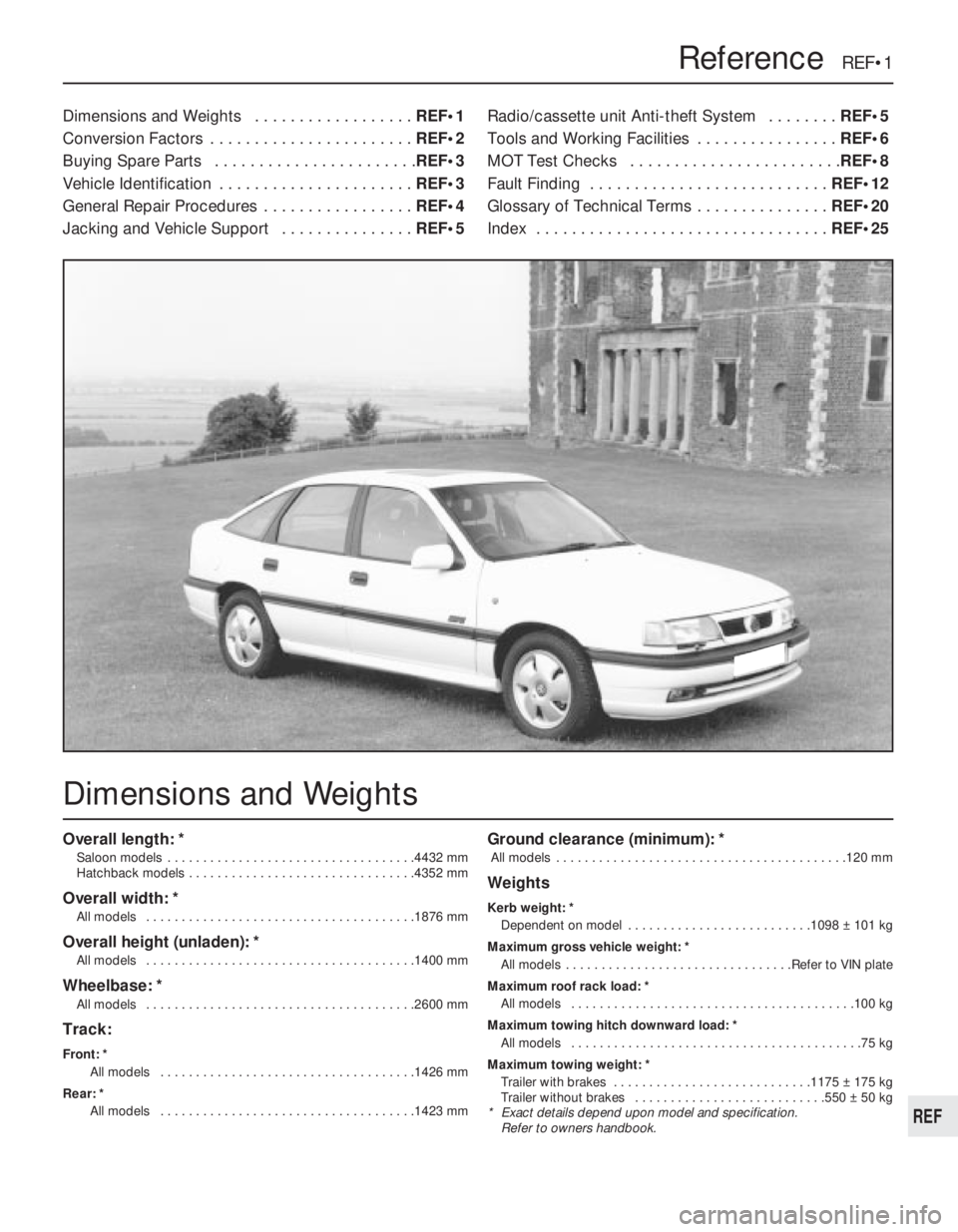
Dimensions and Weights . . . . . . . . . . . . . . . . . .REF•1
Conversion Factors . . . . . . . . . . . . . . . . . . . . . . .REF•2
Buying Spare Parts . . . . . . . . . . . . . . . . . . . . . . .REF•3
Vehicle Identification . . . . . . . . . . . . . . . . . . . . . .REF•3
General Repair Procedures . . . . . . . . . . . . . . . . .REF•4
Jacking and Vehicle Support . . . . . . . . . . . . . . .REF•5Radio/cassette unit Anti-theft System . . . . . . . .REF•5
Tools and Working Facilities . . . . . . . . . . . . . . . .REF•6
MOT Test Checks . . . . . . . . . . . . . . . . . . . . . . . .REF•8
Fault Finding . . . . . . . . . . . . . . . . . . . . . . . . . . .REF•12
Glossary of Technical Terms . . . . . . . . . . . . . . .REF•20
Index . . . . . . . . . . . . . . . . . . . . . . . . . . . . . . . . .REF•25
Reference REF•1
Dimensions and Weights
Page 259 of 525
REF•20Glossary of Technical Terms
A
ABS (Anti-lock brake system)A system,
usually electronically controlled, that senses
incipient wheel lockup during braking and
relieves hydraulic pressure at wheels that are
about to skid.
Air bag An inflatable bag hidden in the
steering wheel (driver’s side) or the dash or
glovebox (passenger side). In a head-on
collision, the bags inflate, preventing the
driver and front passenger from being thrown
forward into the steering wheel or windscreen.
Air cleanerA metal or plastic housing,
containing a filter element, which removes
dust and dirt from the air being drawn into the
engine.
Air filter elementThe actual filter in an air
cleaner system, usually manufactured from
pleated paper and requiring renewal at regular
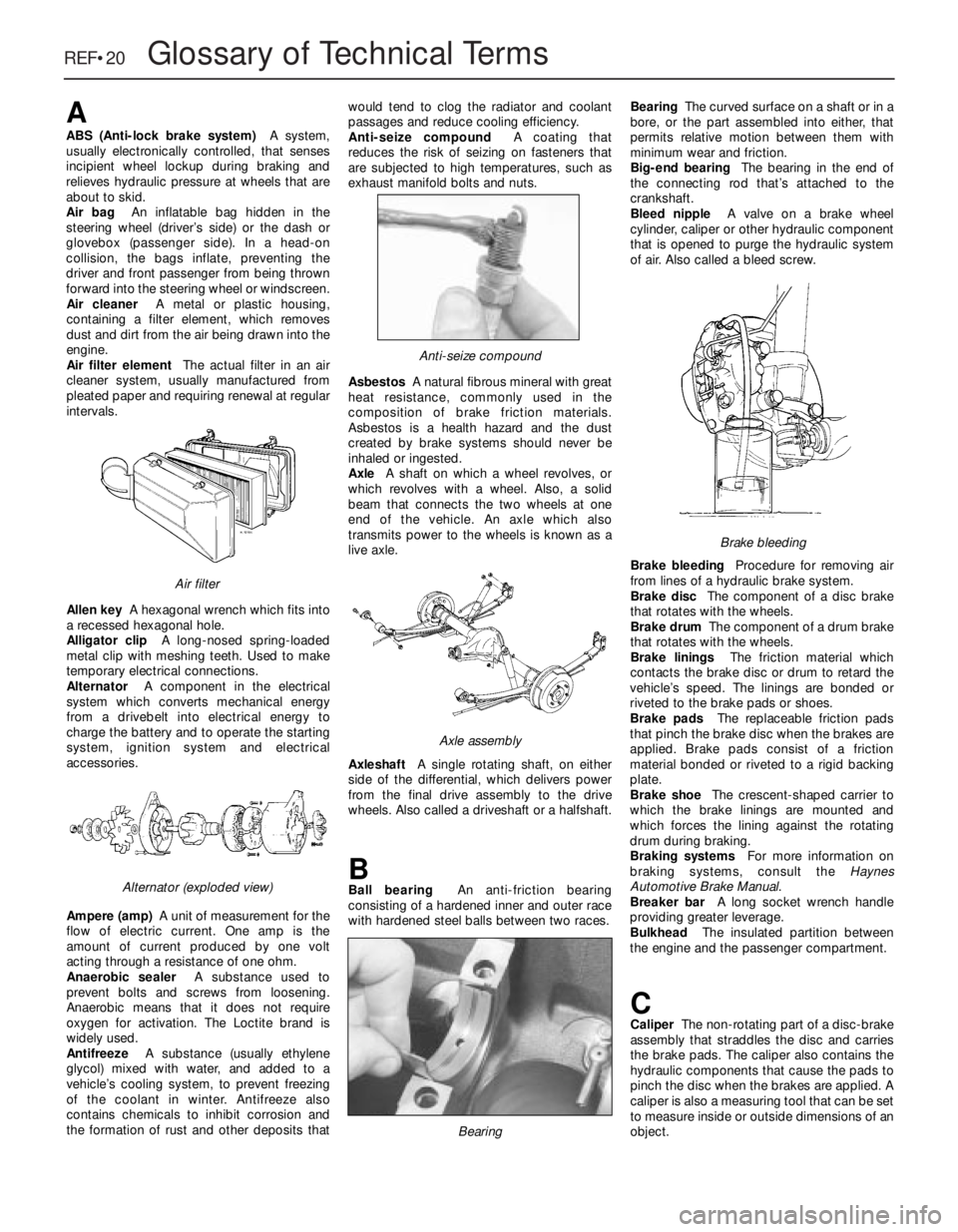
intervals.
Allen keyA hexagonal wrench which fits into
a recessed hexagonal hole.
Alligator clipA long-nosed spring-loaded
metal clip with meshing teeth. Used to make
temporary electrical connections.
AlternatorA component in the electrical
system which converts mechanical energy
from a drivebelt into electrical energy to
charge the battery and to operate the starting
system, ignition system and electrical
accessories.
Ampere (amp)A unit of measurement for the
flow of electric current. One amp is the
amount of current produced by one volt
acting through a resistance of one ohm.
Anaerobic sealerA substance used to
prevent bolts and screws from loosening.
Anaerobic means that it does not require
oxygen for activation. The Loctite brand is
widely used.
AntifreezeA substance (usually ethylene
glycol) mixed with water, and added to a
vehicle’s cooling system, to prevent freezing
of the coolant in winter. Antifreeze also
contains chemicals to inhibit corrosion and
the formation of rust and other deposits thatwould tend to clog the radiator and coolant
passages and reduce cooling efficiency.
Anti-seize compoundA coating that
reduces the risk of seizing on fasteners that
are subjected to high temperatures, such as
exhaust manifold bolts and nuts.
AsbestosA natural fibrous mineral with great
heat resistance, commonly used in the
composition of brake friction materials.
Asbestos is a health hazard and the dust
created by brake systems should never be
inhaled or ingested.
AxleA shaft on which a wheel revolves, or
which revolves with a wheel. Also, a solid
beam that connects the two wheels at one
end of the vehicle. An axle which also
transmits power to the wheels is known as a
live axle.
AxleshaftA single rotating shaft, on either
side of the differential, which delivers power
from the final drive assembly to the drive
wheels. Also called a driveshaft or a halfshaft.
BBall bearingAn anti-friction bearing
consisting of a hardened inner and outer race
with hardened steel balls between two races.BearingThe curved surface on a shaft or in a
bore, or the part assembled into either, that
permits relative motion between them with
minimum wear and friction.
Big-end bearingThe bearing in the end of
the connecting rod that’s attached to the
crankshaft.
Bleed nippleA valve on a brake wheel
cylinder, caliper or other hydraulic component
that is opened to purge the hydraulic system
of air. Also called a bleed screw.
Brake bleedingProcedure for removing air
from lines of a hydraulic brake system.
Brake discThe component of a disc brake
that rotates with the wheels.
Brake drumThe component of a drum brake
that rotates with the wheels.
Brake liningsThe friction material which
contacts the brake disc or drum to retard the
vehicle’s speed. The linings are bonded or
riveted to the brake pads or shoes.
Brake padsThe replaceable friction pads
that pinch the brake disc when the brakes are
applied. Brake pads consist of a friction
material bonded or riveted to a rigid backing
plate.
Brake shoeThe crescent-shaped carrier to
which the brake linings are mounted and
which forces the lining against the rotating
drum during braking.
Braking systemsFor more information on
braking systems, consult the Haynes
Automotive Brake Manual.
Breaker barA long socket wrench handle
providing greater leverage.
BulkheadThe insulated partition between
the engine and the passenger compartment.
CCaliperThe non-rotating part of a disc-brake
assembly that straddles the disc and carries
the brake pads. The caliper also contains the
hydraulic components that cause the pads to
pinch the disc when the brakes are applied. A
caliper is also a measuring tool that can be set
to measure inside or outside dimensions of an
object.
Brake bleeding
Bearing
Axle assembly
Anti-seize compound
Alternator (exploded view)
Air filter
Page 263 of 525
REF•24Glossary of Technical Terms
automatic transmission, a switch that
prevents starting if the vehicle is not in Neutral
or Park.
StrutSee MacPherson strut.
TTappetA cylindrical component which
transmits motion from the cam to the valve
stem, either directly or via a pushrod and
rocker arm. Also called a cam follower.
ThermostatA heat-controlled valve that
regulates the flow of coolant between the
cylinder block and the radiator, so maintaining
optimum engine operating temperature. A
thermostat is also used in some air cleaners in
which the temperature is regulated.
Thrust bearingThe bearing in the clutch
assembly that is moved in to the release levers
by clutch pedal action to disengage the
clutch. Also referred to as a release bearing.
Timing beltA toothed belt which drives the
camshaft. Serious engine damage may result
if it breaks in service.
Timing chainA chain which drives the
camshaft.
Toe-inThe amount the front wheels are
closer together at the front than at the rear. On
rear wheel drive vehicles, a slight amount of
toe-in is usually specified to keep the front
wheels running parallel on the road by
offsetting other forces that tend to spread the
wheels apart.
Toe-outThe amount the front wheels are
closer together at the rear than at the front. Onfront wheel drive vehicles, a slight amount of
toe-out is usually specified.
ToolsFor full information on choosing and
using tools, refer to the Haynes Automotive
Tools Manual.
TracerA stripe of a second colour applied to
a wire insulator to distinguish that wire from
another one with the same colour insulator.
Tune-upA process of accurate and careful
adjustments and parts replacement to obtain
the best possible engine performance.
TurbochargerA centrifugal device, driven by
exhaust gases, that pressurises the intake air.
Normally used to increase the power output
from a given engine displacement, but can
also be used primarily to reduce exhaust
emissions (as on VW’s “Umwelt” Diesel
engine).
UUniversal joint or U-jointA double-pivoted
connection for transmitting power from a
driving to a driven shaft through an angle. A U-
joint consists of two Y-shaped yokes and a
cross-shaped member called the spider.
VValveA device through which the flow of
liquid, gas, vacuum, or loose material in bulk
may be started, stopped, or regulated by a
movable part that opens, shuts, or partiallyobstructs one or more ports or passageways.
A valve is also the movable part of such a
device.
Valve clearanceThe clearance between the
valve tip (the end of the valve stem) and the
rocker arm or tappet. The valve clearance is
measured when the valve is closed.
Vernier caliperA precision measuring
instrument that measures inside and outside
dimensions. Not quite as accurate as a
micrometer, but more convenient.
ViscosityThe thickness of a liquid or its
resistance to flow.
VoltA unit for expressing electrical “pressure”
in a circuit. One volt that will produce a current
of one ampere through a resistance of one
ohm.
WWeldingVarious processes used to join metal
items by heating the areas to be joined to a
molten state and fusing them together. For
more information refer to the Haynes
Automotive Welding Manual.
Wiring diagramA drawing portraying the
components and wires in a vehicle’s electrical
system, using standardised symbols. For
more information refer to the Haynes
Automotive Electrical and Electronic Systems
Manual.
Page 264 of 525
AABS components- 9•2, 9•16
Accelerator cable- 4A•5, 4B•9
Accelerator pedal- 4A•5
Acknowledgements- 0•4
Aerial- 12•17
Air cleaner- 1•3, 1•13, 4A•3, 4B•4
Air box- 4B•5
Air pump/cut off valve- 4C•2
Air temp control- 4B•5
Air vents- 3•8
Airbag- 12•19
Airflow meters- 4B•12
Alternator- 5•5
Alternator V-belt check- 1•12
Anti theft alarm- 12•19
Anti-roll bars- 10•8, 10•13, 10•17
Antifreeze mixture- 0•12, 0•17, 1•2, 3•3
ATF- 0•17, 1•2, 1•11, 7B•3
Automatic choke unit- 4A•9
Automatic transmission- 7B•1 et seq
cooler pipes and hoses - 7B•5
ECU - 7B•5
fault diagnosis - REF•12, REF•16
fluid - 0•17, 1•2, 1•11, 7B•3
kickdown switch - 7B•3
removal and refitting - 7B•6
selector control cable - 7B•4
speed sensors - 7B•6
starter inhibitor switch - 7B•3
temperature sensor - 7B•5
BBattery- 0•6, 0•15, 5•5
Bearings (engine)- 2A•31
Bleeding the brakes- 9•3
Bleeding the power steering- 10•22
Blower motor- 3•7
Body damage- 11•2
Body electrical systems - 12•1 et seq
Bodywork and fittings- 11•1 et seq
Bonnet- 11•4
Bonnet lock/release cable- 11•4
Boot lid- 11•4
Boot lid lock- 11•5
Bores- 2A•33
Brake checks- 1•12,
Braking system- 9•1 et seq
ABS components - 9•2, 9•16
backplate - 9•12
bleeding the brakes - 9•3
brake caliper - 9•8
brake disc - 9•10
brake drum - 9•11
brake fluid pipes and hoses - 9•18
brake lamp switch - 12•5
brake pads - 9•4
brake pedal - 9•21
brake shoes - 9•6
disc shield - 9•13
fault diagnosis - REF•12, REF•17
fluid - 0•13, 0•17handbrake adjustment - 9•18
handbrake cables - 9•19
handbrake lever - 9•20
master cylinder - 9•13
pressure valves - 9•18
vacuum servo unit - 9•15
wheel cylinder - 9•11
Bulbs- 12•2, 12•7, 12•11
Bumpers- 11•11
CCables:
bonnet release - 11•4
clutch - 6•2
handbrake - 9•19
selector automatic transmission - 7B•4
speedometer - 12•18
throttle - 4A•5, 4B•9
Caliper (brake)- 9•8
Camber- 10•1, 10•24
Camshaft- 2A•19, 2B•6
Camshaft housing- 2A•18
Camshaft oil seals- 2A•18
Capacities- 1•2
Carbon canister- 4C•4
Carburettor- 4A•5, 4A•11
Carpets- 11•2
Castor- 10•1, 10•24
Catalytic converter- 4C•3
Central door locking- 12•16
Centre console- 11•18
Cigarette lighter- 12•5
Clock- 12•6
Clutch- 6•1 et seq
cable - 6•2
fault diagnosis - REF•12, REF•15
pedal - 6•3
release bearing - 6•6
removal, inspection and refitting - 6•3
Coil- 5•9
Coil spring (rear)- 10•12, 10•15
Compression test- 2A•8
Computer components- 12•7
Connecting rods- 2A•29
Contents- 0•2
Control units- 4B•16, 7B•5
Conversion factors- REF•2
Coolant- 0•12, 0•17, 1•2, 3•3
Cooling, heating and ventilation systems-
3•1 et seq
blower motor - 3•7
coolant level sensor - 3•5
coolant pump - 3•4
cooling fan - 3•5
draining - 3•2
expansion tank - 3•5
fan switch - 3•6
fault diagnosis - REF•12, REF•15
filling - 3•2
flushing - 3•2
heater control panel - 3•6
heater matrix - 3•7
radiator - 3•3temperature gauge sender - 3•6
thermostat - 3•4
vents - 3•8
Courtesy lamp switch- 12•5
Crankcase ventilation system- 2A•7
Crankshaft- 2A•31
Crankshaft oil seals- 2A•26, 2B•6, 2B•9
Cylinder bores- 2A•33
Cylinder head- 2A•19, 2A•22, 2B•7DDents- 11•2
Depressurising fuel system- 4B•5
Differential bearing oil seal- 7A•3
Dimensions and weights- REF•1
Disc (brake)- 9•10
Distributor- 5•10
Door- 11•6
handle - 11•7
inner trim panel - 11•6
lock key battery - 1•13
mirror - 11•11
Driveshafts- 8•1 et seq
fault diagnosis - REF•12, REF•16
gaiter - 8•4
joint renewal - 8•4
Drum (brake)- 9•11
EEarth fault finding- 12•2
ECU’s - 4B•16, 7B•5
EGR components- 4C•2
Electric windows- 12•15
Electrical fault finding- 12•2
Electrical system (body)- 12•1 et seq
Electrical system- 0•14, 5•2
Electrical system fault diagnosis- REF•12,
REF•18
Electronic control units- 4B•16, 7B•5
Engine:
bearings - 2A•31
camshaft - 2A•19, 2B•6
camshaft housing - 2A•18
camshaft oil seals - 2A•18, 2B•6
codes - 2A•1, 2B•1
compartment - 0•10, 1•5
compression test - 2A•8
connecting rods - 2A•29
crankcase ventilation - 2A•7
crankshaft - 2A•31
crankshaft oil seals - 2A•26, 2B•6, 2B•9
cylinder bores - 2A•33
cylinder head - 2A•19, 2A•22, 2B•7
dismantling - 2A•12
DOHC - 2B•1 et seq
electrical systems - 5•1 et seq
fault diagnosis - REF•12, REF•13
flexplate (automatic transmission) - 2A•26
flywheel - 2A•26
main and big-end bearings - 2A•31
mountings (engine/transmission) - 2A•12,
2B•3
Index REF•25
REF
Note:References throughout this index are in the form - “Chapter number” • “page number”