Page 251 of 962
Release Bearing
Replace release bearing if it sticks, rattles or
makes abnormal noise when spun anaturned by
hand.
Fig. 11-10
Input Shaft Bearing
Replace input shaft bearing if it sticks, rattles or
makes abnormal noise when spun and turned by
hand.
Flywheel
Check surface contacting clutch disc for any
wear or damage.
Fig. 11-12
Fig. 1 I- 11
11-6
Page 252 of 962
114. INSTALLATION
Install clutch by reversing removal procedure.
Some important steps will be explained below.
Flywheel
1) Tighten bolts to specification.
1.Flywheel
2.Flywheel bolt
3.Special tool (Flywheel holder 09924-l 7810)
Fig. 11-13 4*Input shaft bearing
2) Install input shaft end bearing to flywheel
using bearing installer (special tool).
1. Input shaft bearing2. Special tool (Input shaft bearing installer 09925-98210)
Fig. 1 l- 13- 1
Clutch Disc and Clutch Cover
Using special tool (clutch center guide), install
clutch disc and clutch cover.
Tighten clutch cover bolts to specification using
special tool (Flywheel holder).
1.2.
3.
4.
Fig. 1 l-14
Special tool (Clutch center guide 09923-38220)
Clutch cover
Clutch cover boltSpecial tool (Flywheel holder 09924-l 7810)
Clutch Release Bearing
Before installing retainer, apply grease to its
inner surface.
Fig. 1 I- 15 @ Grease (SUZUKI SUPER
GREASE “A’,)
11-7
Page 255 of 962
2) For right-hand side steering vehicle.
Air cleaner outlethoseAircleaner
Radiator outlet
Air cleaner outlet hose
Clutch cable
Cla&p
Viewed from arrow “A”
40 - 60 N.m4.0 - 6.0 kg-m
I
Viewedfrom arrow“6”
Radiator
Fig. 11-23
Warmair hoseViewed from arrow “C”
11-6. RECOMMENDED TORQUE SPECIFICATION
Be sure to torque each nut or bolt, if loosened, to specification given below.
If specified tightening torque for particular bolt or nut is not included here, refer to p. O-12 of this manual.
Fastening PartsTightening torque
, N.mkg-mlb-ft
1.Flywheelbolts57-655.7-6.541.5-47.0
2.Clutchcover bolts18-281.B-2.613.5-20.0
3.Clutchrelease armboltandnutlo- 161.O-1.67.5-11.5.
11-10
Page 289 of 962

14-1. GENERAL DESCRIPTION
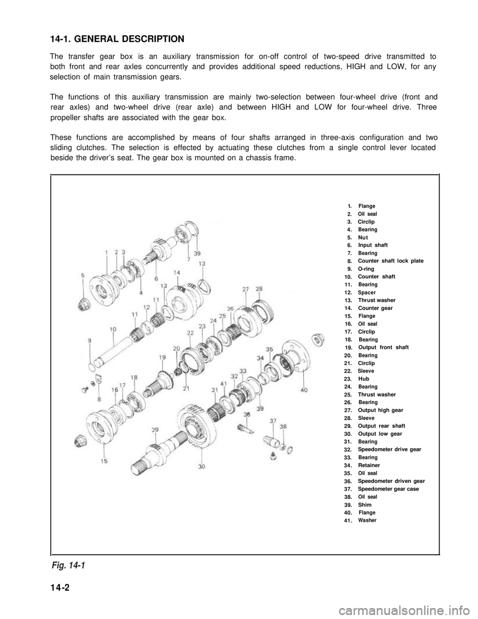
The transfer gear box is an auxiliary transmission for on-off control of two-speed drive transmitted to
both front and rear axles concurrently and provides additional speed reductions, HIGH and LOW, for any
selection of main transmission gears.
The functions of this auxiliary transmission are mainly two-selection between four-wheel drive (front and
rear axles) and two-wheel drive (rear axle) and between HIGH and LOW for four-wheel drive. Three
propeller shafts are associated with the gear box.
These functions are accomplished by means of four shafts arranged in three-axis configuration and two
sliding clutches. The selection is effected by actuating these clutches from a single control lever located
beside the driver’s seat. The gear box is mounted on a chassis frame.
1.Flange
2.Oil seal
3.Circlip
4.Bearing
5.Nut6.Input shaft
7.Bearing
8.Counter shaft lock plate
9.O-ring
10.Counter shaft
11.Bearing
12.Spacer
13.Thrust washer
14.Counter gear
15.Flange
16.Oil seal
17.Circlip
18.Bearing
19.Output front shaft
20.Bearing
21.Circlip
22.Sleeve
23.Hub
24.Bearing
25.Thrust washer
26.Bearing
27.Output high gear
28.Sleeve
29.Output rear shaft
30.Output low gear
31.Bearing
32.Speedometer drive gear
33.Bearing
34.Retainer
35.Oil seal
36.Speedometer driven gear
37.Speedometer gear case
38.Oil seal
39.Shim
40.Flange
41.Washer
Fig. 14- 1
14-2
Fig. 14-1
Page 290 of 962
14-2. SELECTIVE FLOWS OF TRANSFER DRIVE
2-Wheel Drive (Rear-Wheel Drive)
Rear shifter fork pushes rear clutch sleeve into
“high” gear, thus coupling the gear to output
rear shaft.
Drive flows from input shaft to output rear shafttra”SmiSSion
through big gear, “high” gear and rear clutch.
Gear shift control lever position
a-wheel drive
(Rear wheel drive)
Fig. 14-2
4-Wheel Drive HIGH (All-Wheel Drive on HIGH)
Under the conditions of rear-wheel drive,
described above, front shifter fork pushes the
sleeve of front clutch onto the toothed clutch From .
ring, thus coupling output rear shaft to output transm’ss’on
shaft runefront shaft. Front shaft and rear
together on HIGH.
Gear shift control lever position
4-wheeldrive HIGH
To front wheel
Fig. 14-314-3
Page 291 of 962
4-Wheel Drive LOW (All-Wheel Drive on LOW)
Gear shift control lever position
4-wheeldrive LOW
2H
5l
Front shifterforkactuates front clutch to couple
rear shaft to front shaft; and rear shifter fork
actuates rear clutch to couple “low” gear to rear
shaft. Front shaft and rear shaft run together on From
LOW.
To front whe
Fig. 14-4
14-3. GEAR RATIO DATA
Gear
Reduction
Rear-wheel drive
41/44 - 62/41
1.409
All-wheel drive high
41/44 62/41-
1.409
All-wheel drive low
41/44 - 56/23
2.268
14-4
Page 312 of 962
151. GENERAL DESCRIPTION
These automobiles, covered in this manual are four-wheel drive machines and, as such, use three propeller
shafts designated as No. 1, No. 2 and No. 3.
No, 1 propeller shaft transmits drive from the transmission to the transfer gear box. No. 2 shaft and No. 3
shaft extend from the transfer gear box, the former driving the front axle and the latter the rear axle.
The cross spider in each universal joint is fitted with four needle roller bearings.
From
TQ transfer
transmission casaTo transfar casa
Propeller shaft No. 2
To rear differential
To front differential
To transfer case
15-2
Fig. 15-1
Page 321 of 962

16-2. REMOVAL
1. Loosen, but do not remove, wheel nuts of
front or rear wheels, and raise car off the
2.
3.
floor by jacking.
Rest car steady on safety stands.
Drain out oil in differential housing by
loosening drain plug.
Remove wheel nuts and take off wheels,
front or rear. Each wheel has five wheel nuts.
For Front Differential
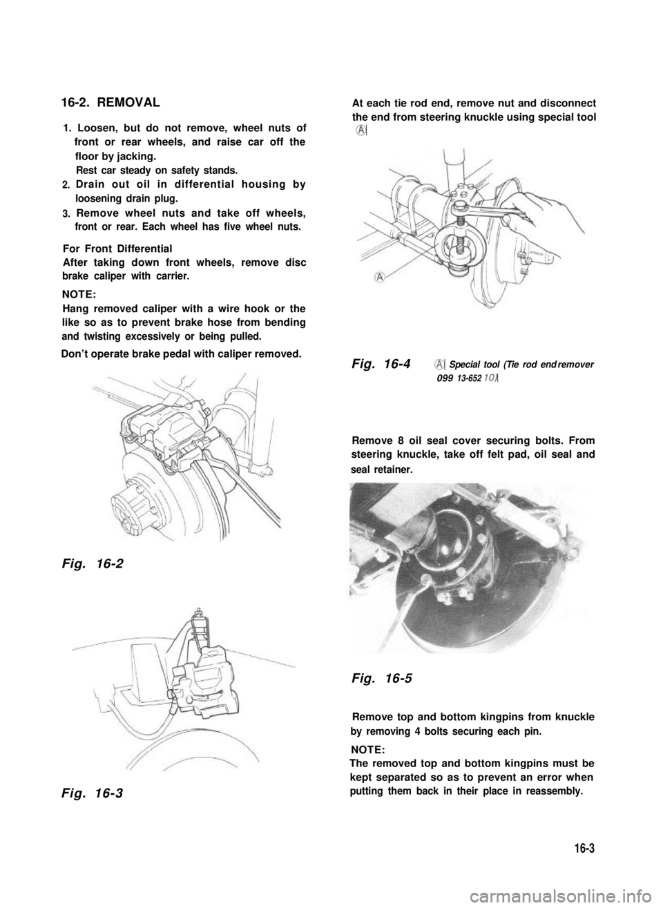
After taking down front wheels, remove disc
brake caliper with carrier.
NOTE:
Hang removed caliper with a wire hook or the
like so as to prevent brake hose from bending
and twisting excessively or being pulled.
Don’t operate brake pedal with caliper removed.
Fig. 16-2
Fig. 16-3
At each tie rod end, remove nut and disconnect
the end from steering knuckle using special tool
@
Fig. 16-4@ Special tool (Tie rod end remover
099 13-652 10)
Remove 8 oil seal cover securing bolts. From
steering knuckle, take off felt pad, oil seal and
seal retainer.
Fig. 16-5
Remove top and bottom kingpins from knuckle
by removing 4 bolts securing each pin.
NOTE:
The removed top and bottom kingpins must be
kept separated so as to prevent an error when
putting them back in their place in reassembly.
16-3