Page 425 of 962
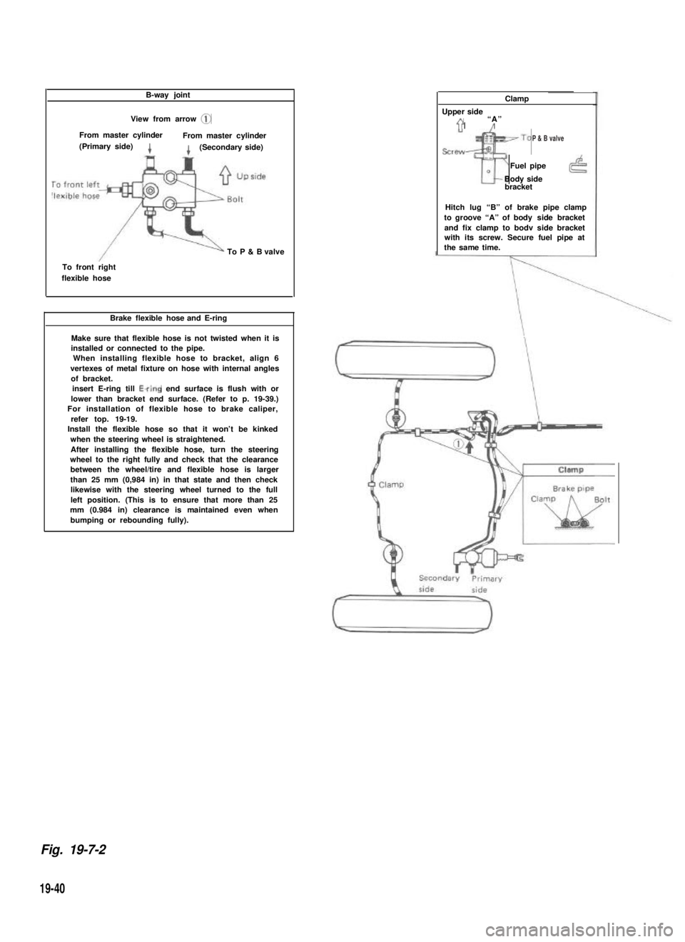
B-way joint
View from arrow @
From master cylinderFrom master cylinder(Primary side)4(Secondary side)
To P & B valve
To front rightflexible hose
Brake flexible hose and E-ring
Make sure that flexible hose is not twisted when it isinstalled or connected to the pipe.When installing flexible hose to bracket, align 6vertexes of metal fixture on hose with internal anglesof bracket.insert E-ring till Ewing end surface is flush with orlower than bracket end surface. (Refer to p. 19-39.) For installation of flexible hose to brake caliper,refer top. 19-19. Install the flexible hose so that it won’t be kinkedwhen the steering wheel is straightened.After installing the flexible hose, turn the steeringwheel to the right fully and check that the clearancebetween the wheel/tire and flexible hose is largerthan 25 mm (0,984 in) in that state and then checklikewise with the steering wheel turned to the fullleft position. (This is to ensure that more than 25mm (0.984 in) clearance is maintained even whenbumping or rebounding fully).
Clamp
Upper sideA“A”71’/
sre~~To
Tr
Fuel pipe0Body sidebracket
Hitch lug “B” of brake pipe clampto groove “A” of body side bracketand fix clamp to bodv side bracketwith its screw. Secure fuel pipe atthe same time.
Fig. 19-7-2
19-40
P & B valve
Page 426 of 962
Clamp
Up side
Brake pipe
Brake pipes (Right side)
Install brake pipe to
Up sidewheel cylinder pro-perly using care forits installing posi-tion.
cylinder
Blake backing Plato (Right & Left)
When installing backing plateontoaxle housing, applySEALING COMPOUND 366E(99000-31090) to mating sur-faces of both parts.
Brake backing plate
compound
hose groove securelyand clamp hose.
Air bleeder
(To flexible hose)
wheel cylinder pro-perly using care foritsinstallrng posi-tion.
Rear axle
IBrake pipe
1Rear axle
P & B valve
View from arrow @
Up side
From 6-way joint
Plug
To rear flexible hose
19-41
Page 429 of 962
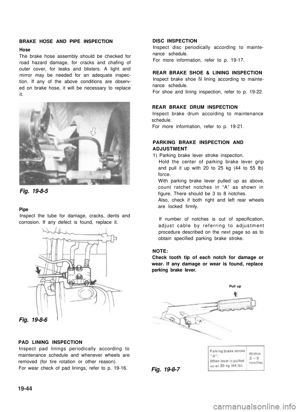
BRAKE HOSE AND PIPE INSPECTION
Hose
The brake hose assembly should be checked for
road hazard damage, for cracks and chafing of
outer cover, for leaks and blisters. A light and
mirror may be needed for an adequate inspec-
tion. If any of the above conditions are observ-
ed on brake hose, it will be necessary to replace
it.
DISC INSPECTION
Inspect disc periodically according to mainte-
nance schedule.
For more information, refer to p. 19-17.
REAR BRAKE SHOE & LINING INSPECTION
Inspect brake shoe & lining according to mainte-
nance schedule.
For shoe and lining inspection, refer to p. 19-22.
Fig. 19-8-5
Pipe
Inspect the tube for damage, cracks, dents and
corrosion. If any defect is found, replace it.
Fig. 19-8-6\ ’
PAD LINING INSPECTION
Inspect pad linings periodically according to
maintenance schedule and whenever wheels are
removed (for tire rotation or other reason).
For wear check of pad linings, refer to p. 19-16.
REAR BRAKE DRUM INSPECTION
Inspect brake drum according to maintenance
schedule.
For more information, refer to p. 19-21.
PARKING BRAKE INSPECTION AND
ADJUSTMENT
1) Parking brake lever stroke inspection.
Hold the center of parking brake lever grip
and pull it up with 20 to 25 kg (44 to 55 lb)
force.
With parking brake lever pulled up as above,
count ratchet notches in “A” as shown in
figure. There should be 3 to 8 notches.
Also, check if both right and left rear wheels
are locked firmly.
If number of notches is out of specification,
adjust cable by referring to adjustment
procedure described on the next page so as to
obtain specified parking brake stroke.
NOTE:
Check tooth tip of each notch for damage or
wear. If any damage or wear is found, replace
parking brake lever.
Pull up
4
Fig. 19-8-7
19-44
Page 431 of 962
BLEEDING BRAKES
NOTE:
Brake fluid is extremely damaging to paint. If
fluid should accidentally touch painted surface,
immediately wipe fluid from paint and clean
painted surface.
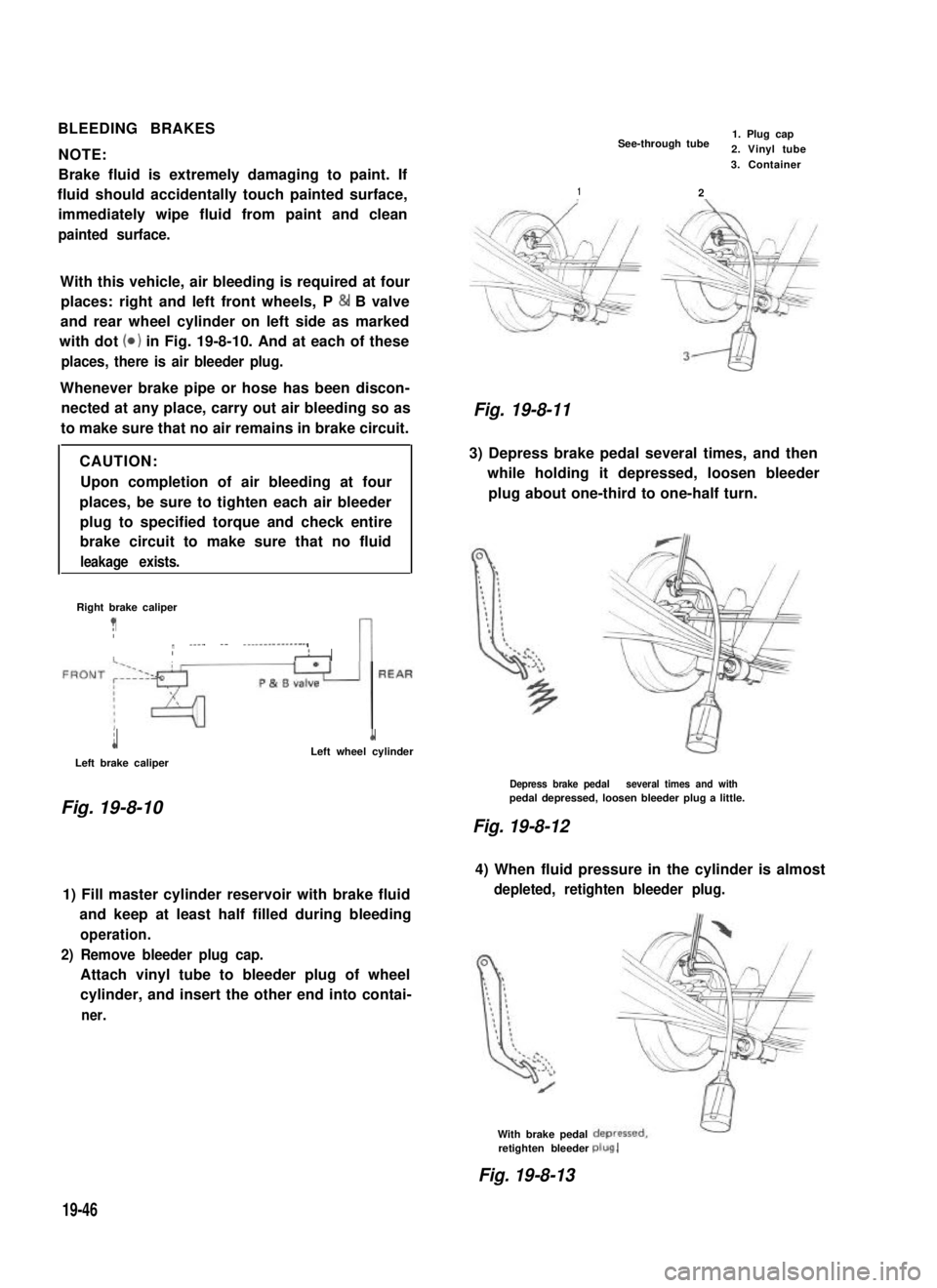
With this vehicle, air bleeding is required at four
places: right and left front wheels, P & B valve
and rear wheel cylinder on left side as marked
with dot (0) in Fig. 19-8-10. And at each of these
places, there is air bleeder plug.
Whenever brake pipe or hose has been discon-
nected at any place, carry out air bleeding so as
to make sure that no air remains in brake circuit.
CAUTION:
Upon completion of air bleeding at four
places, be sure to tighten each air bleeder
plug to specified torque and check entire
brake circuit to make sure that no fluid
leakage exists.
Right brake caliper
?Ir ____ -- ---------------,IIAn
i
Left brake caliper
1Left wheel cylinder
Fig. 19-8-10
1) Fill master cylinder reservoir with brake fluid
and keep at least half filled during bleeding
operation.
2) Remove bleeder plug cap.
Attach vinyl tube to bleeder plug of wheel
cylinder, and insert the other end into contai-
ner.
See-through tube1. Plug cap2. Vinyl tube
2
3. Container
1
Fig. 19-8-11
3) Depress brake pedal several times, and then
while holding it depressed, loosen bleeder
plug about one-third to one-half turn.
Depress brake pedal several times and withpedal depressed, loosen bleeder plug a little.
Fig. 19-8-12
4) When fluid pressure in the cylinder is almost
depleted, retighten bleeder plug.
With brake pedalretighten bleederplug.
Fig. 19-8-13
19-46
Page 448 of 962
21-1.COMBINATION METER..................................
21-2.HEAD LIGHT..........................................
21-3.TURN SIGNAL LIGHT AND HAZARD WARNING LIGHT.......
21-4.WINDSHIELD WIPER MOTOR.............................
21-5.WATER TEMPERATURE METER AND GAUGE...............
21-6.FUEL LEVEL METER AND GAUGE........................
21-7.BRAKE WARNING LAMP ...............................
21-8.OIL PRESSURE LAMP..................................
4 WHEEL DRIVE LAMP.................................
21-10. SEAT BELT WARNING LAMP/BUZZER.....................
...................
...~I-I
.....
21-14. .............................................
21-15. WIRING HARNESS ROUTING............................
21-16. WIRING DIAGRAM....................................
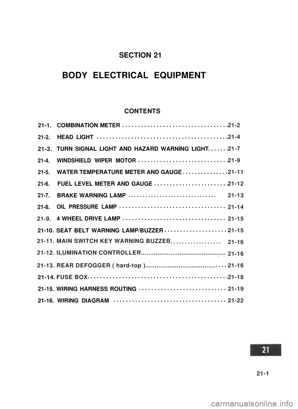
SECTION 21
BODY ELECTRICAL EQUIPMENT
CONTENTS
21-9.
21-11. MAIN SWITCH KEY WARNING BUZZER
21-12. ILUMINATION CONTROLLER..............................................
21-13. REAR DEFOGGER ( hard-top )......................................
FUSE BOX
21-2
21-4
21-7
21-9
21-11
21-12
21-13
21-14
21-15
21-15
21-16
21-16
21-16
21-18
21-19
21-22
21-1
Page 462 of 962
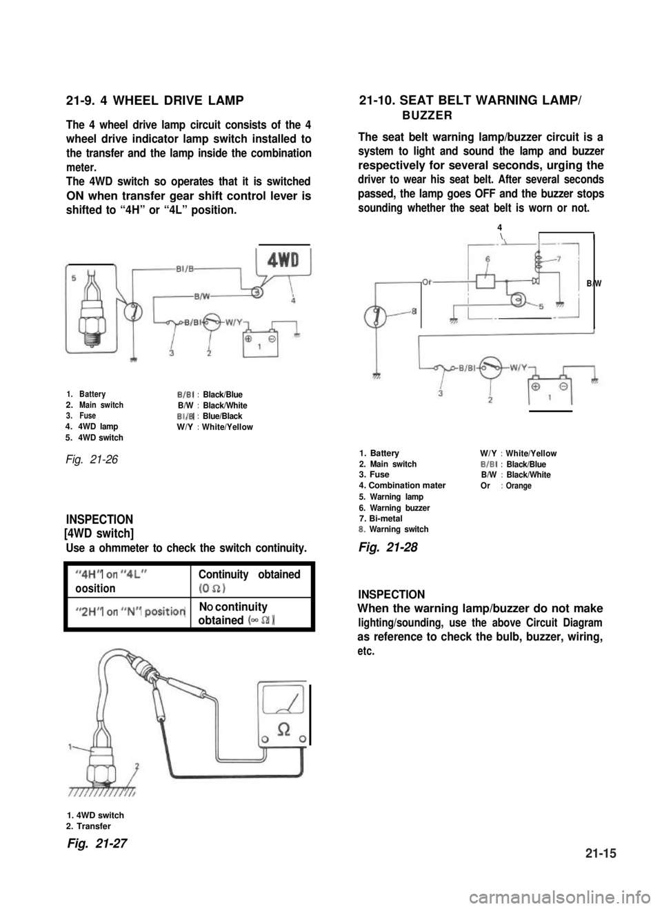
21-9. 4 WHEEL DRIVE LAMP21-10. SEAT BELT WARNING LAMP/
BUZZERThe 4 wheel drive lamp circuit consists of the 4
wheel drive indicator lamp switch installed to
the transfer and the lamp inside the combination
meter.
The 4WD switch so operates that it is switched
ON when transfer gear shift control lever is
shifted to “4H” or “4L” position.
The seat belt warning lamp/buzzer circuit is a
system to light and sound the lamp and buzzer
respectively for several seconds, urging the
driver to wear his seat belt. After several seconds
passed, the lamp goes OFF and the buzzer stops
sounding whether the seat belt is worn or not.
1.BatteryB/B1:Black/Blue2.Main switchB/W:Black/White3.FuseBI/B:Blue/Black4.4WD lampW/Y:White/Yellow5.4WD switch
Fig. 21-26
INSPECTION
[4WD switch]
Use a ohmmeter to check the switch continuity.
I
“4H” or “4L”Continuity obtained
oosition(052)I
I
#,2HM or ##N## positionNO continuity
obtained (- 52 1I
CL-
01
8
4\II
B/W
1. Battery
2. Main switch3. Fuse
4. Combination mater
5. Warning lamp
6. Warning buzzer7. Bi-metal8. Warning switch
W/Y:White/Yellow
BIBI:Black/BlueB/W:Black/White
Or:Orange
Fig. 21-28
INSPECTION
When the warning lamp/buzzer do not make
lighting/sounding, use the above Circuit Diagram
as reference to check the bulb, buzzer, wiring,
etc.
1. 4WD switch
2. Transfer
Fig. 21-2721-15
Page 472 of 962
Convertible/Hard Top
WHEEL AND SUSPENSIONI
Tire size: front and rear1 P205/70 R15I
Tire pressurefront
rear
Suspension typefront
rear
140 kPa (1.40 kg/cm’, 20 psi)
140 kPa (1.40 kg/cm’, 20 psi)-unladen
180 kPa (1.80 kg/cm*, 26 psi)-laden
Leaf spring
Leaf spring
STEERING
Turning radius1 5.1 m (16.7ft)
1 Steering gear box1Ball nut typeI
Toe-in
Camber angle
Caster angle
King pin angle
BRAKE SYSTEM
Type
Wheel brake
Parking brake
CAPACITIES
Cooling solution
Fuel tank
2 - 6 mm (0.08 - 0.24 in.)
lo 00’
) 3º 30’I
front
rear
9º 00’
4-wheel, hydraulic
Disc brake (floating caliper type)
Drum brake (leading and trailing)
Mechanical actuated on rear wheels
4.8 Q (10.1/8.4 US/Imp pt)
4OQ (10.6/8.8 US/Imp cral)
Engine oil
Transmission oil
Differential gear
box oil
Transfer gear box oil
front
rear
3.5 II (7.4/6.2 US/Imp pt)
1.3 II (2.7/2.3 US/Imp pt)
2.0 Q (4.2/3.5 US/Imp pt)
1.5 II (3.2/2.6 US/Imp pt)
0.8 !? (1.7/l .4 US/Imp pt)
22-3