Page 364 of 962

SECTION 18
STEERING SYSTEM
CONTENTS
18-1.GENERAL DESCRIPTION............................... 18-4
18-2.SPECIFICATIONS AND DATA............................18-4
STEERING GEAR BOX CONSTRUCTION AND OPERATION...18-5
18-4.REMOVAL...........................................18-6
18-5.INSPECTION OF COMPONENTS..........................
CHECKING STEERING COLUMN FOR ACCIDENT DAMAGE.
18-7.IMPORTANT STEPS IN REINSTALLATION..................
18-8.WHEEL ALIGNMENT..................................
18-9.MAINTENANCE SERVICES.............................
18-10. RECOMMENDED TORQUE SPECIFICATIONS..............
NOTE:
All steering system fasteners are important parts in that they could affect the performance
of vital parts and systems, and/or could result in major repair expense. They must be
replaced with one of the same part number or with an equivalent part if replacement
becomes necessary. Do not use a replacement part of lesser quality or substitute design.
Torque values must be used as specified during reassembly to assure proper retention of
this part.
18-1
18-3.
18-9
18-12
18-11
18-16
18-18
18-22
18-6.
Page 365 of 962

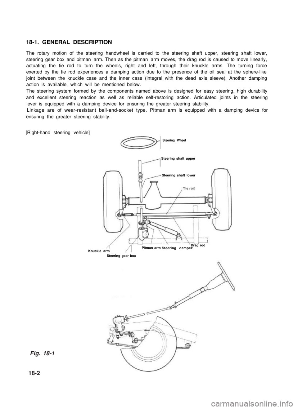
18-1. GENERAL DESCRIPTION
The rotary motion of the steering handwheel is carried to the steering shaft upper, steering shaft lower,
steering gear box and pitman arm. Then as the pitman arm moves, the drag rod is caused to move linearly,
actuating the tie rod to turn the wheels, right and left, through their knuckle arms. The turning force
exerted by the tie rod experiences a damping action due to the presence of the oil seal at the sphere-like
joint between the knuckle case and the inner case (integral with the dead axle sleeve). Another damping
action is available, which will be mentioned below.
The steering system formed by the components named above is designed for easy steering, high durability
and excellent steering reaction as well as reliable self-restoring action. Articulated joints in the steering
lever is equipped with a damping device for ensuring the greater steering stability.
Linkage are of wear-resistant ball-and-socket type. Pitman arm is equipped with a damping device for
ensuring the greater steering stability.
[Right-hand steering vehicle]
Steering Wheel
n’
Steering shaft upper
Steering shaft lower
/Knuckle arm/Steering damper\ Pitman arm
Steering gear box
Drag rod
Fig. 18-1
18-2
Page 366 of 962
[Left-hand steering vehicle]
Drag I
Steering wheel
Steering lower shaft
*odSteering damperSteering gaar box
upper shaft
18-3
Fig. 18-1-1
Page 367 of 962
18-2. SPECIFICATIONS AND DATA
Steering gear boxRecirculating ball-and-nut type
Gear ratio15.6 - 18.1
Steering angle, inside29” + 3”
Steering angle, outside26” + 3”
Steering wheel diameter400 mm (15.74 in.)
Minimum turning radius5.1 m (16.73 ft.)
5
Toe-in2 - 6 mm (0.079 - 0.236 in.)
igCamber1 degree (1”) + 45’
%=Kingpin inclination9 degree (9”) + 2“
SC3_Caster3 degree 30 minutes (3” 30’) + 1”
Side slip0-in3m/km
18-5
AL
Page 368 of 962
18-4. REMOVAL
NOTE:
When removing the column assembly from the
car, special care must be taken in handling it
Use of a steering wheel puller other than the
steering wheel remover recommended in this
manual or a sharp blow on the end of the
steering shaft, leaning on the assembly, or
dropping the assembly is prohibited. Any of
such actions could shear the plastic shear pins
which maintain column length especially.
Steering Hand Wheel
1) Disconnect negative battery cable.
2) Pull horn button to remove.
Fig. 18-3
3) After loosening steering shaft nut, remove
steering wheel by using special tool.
Fig. 18-4 @ Special tool (Steering wheel
remover 09944-36010)
Steering Column
1) After removing steering handwheel according
to the foregoing step, remove steering covers
(lower & upper).
NOTE:
After removing instrument lower panel, loosen
2 screws and 4 nuts securing steering column to
remove upper cover.
Fig. 18-5
18-6
Page 371 of 962

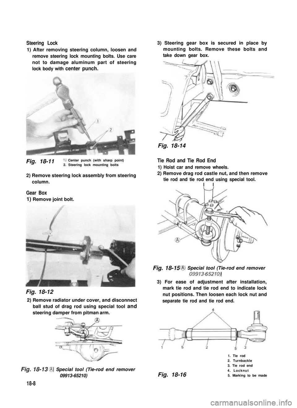
Steering Lock
1) After removing steering column, loosen and
remove steering lock mounting bolts. Use care
not to damage aluminum part of steering
lock body with center punch.
Fig. 18-11 1. Center punch (with sharp point)2. Steering lock mounting bolts
2) Remove steering lock assembly from steering
column.
Gear Box
1) Remove joint bolt.
Fig. 18-12
2) Remove radiator under cover, and disconnect
ball stud of drag rod using special tool and
steering damper from pitman arm.
-----‘CA2
@ Special tool (Tie-rod end remover
09913-65210)
18-8
3) Steering gear box is secured in place by
mounting bolts. Remove these bolts and
take down gear box.
Fig. 18-14
Tie Rod and Tie Rod End
1) Hoist car and remove wheels.
2) Remove drag rod castle nut, and then remove
tie rod and tie rod end using special tool.
I I
Fig. 18-15 @ Special tool (Tie-rod end remover
09913-65210)
3) For ease of adjustment after installation,
mark tie rod and tie rod end to indicate lock
nut positions. Then loosen each lock nut and
separate tie rod and tie rod end.
Fig. 18-16
1. Tie rod
2. Turnbackle
3. Tie rod end
4. Locknut
5. Marking to be made
Fig. 18-13
Page 372 of 962
18-5. INSPECTION OF COMPONENTS
Steering Gear Box
[Oil level]
Oil surface should be up to the level as shown
in below figures. If not, add prescribed gear oil,
SAE 90.
Right hand steering vehicle
Fig. 18-17
Left hand steering vehicle
I
35mm(1.4 in.)
Fig. 18-18
[Adjustment of worm shaft starting torque]
The steering gear box is provided with adjust-
ing bolt @ which gives preload to sector shaft.
Fig. 18-19 (1)Adjusting bolt
Make an adjustment according to the following
procedure.
1) Check worm shaft to ensure that it is free
from thrust play.
2) Position pitman arm in parallel with worm
shaft as shown below.
(With pitman arm in this position, front
wheel is in straightforward state.)
Worm shaft
Fig. 18-20
Pitman arm
18-9
Page 377 of 962
Steering Column
Steering wheel slip ring
Apply SUZUKI SUPER GREASE A
(99000-25010) all around slip ring
IIbefore fining it. , 1
Steering column seal
\I
Steering column bolt
tightening torqueI
When installing the steering column,
1.
make sure to fit seal rubber in the
rubber
1J
Steering column nut
tightening torque
11 - 17N.m
1.1 - 1.7 kg-m
(8.0 - 12.0 lb-ft)
Fig. 18-30
position as illustrated
18-14