Page 340 of 962
Front Wheel Hub 81 Bearing
1. Loosen the five nuts securing the wheel.
Raise the front end by jacking.
Rest the machine steady on safety stands.
2. Remove the five nuts and take off the wheel.
Fig. 17-1-8
3. Remove the caliper with carrier by loosen-
ing carrier bolts.
NOTE:
Hang removed caliper with a wire hook or the
like so as to prevent brake hose from bending
and twisting excessively or being pulled.
Don’t operate brake pedal with caliper removed.
Fig. 17-1-9
4. Remove brake disc.
NOTE:
If brake disc can not be removed by hand, use
8 mm bolts as shown below.
f
@
[For car equipped with free wheeling hub]
5. Remove free wheeling hub cover and circlip.
Fig. 17-1-12-1 @ Circlip remover (09900-06107)
6. Remove free wheeling hub body.
Fig. 17-1-10
17-6Fig. 17-1-12-2
8mm BoltFig. 17-1-11
Page 341 of 962
[For car not equipped with free wheeling hub]
5. Remove the front axle shaft cap.
6. Remove the circlip retaining the front axle
shaft drive flange on front drive shaft, using
the circlip remover @.
Fig. 17-1-12-3 @ Circlip Remover
7. Loosen securing bolts of front axle shaft
drive flange and take off drive flange.
Fig. 17-1-13
8. Straighten bent part of lock washer and
remove wheel bearing lock nut with special
tool @I.
Fig. 17-1-15 Special tool @
(Front Wheel Bearing Nut Socket
Wrench 09941-58010)
9. After loosening front wheel bearing nut
with the same special tool @I as mentioned
in the foregoing step 8, take nut and washer
off the front wheel spindle.
\
Fig. 17-1-16
10. Pull front wheel hub off the front wheel
spindle.
Fig. 17-1-17
17-7Fig. 17-1-14
Page 342 of 962
11. Remove oil seal and outer race of inner
bearing or outer bearing from wheel hub.
Fig. 17-1-18
Steering Knuckle
1. Remove front wheel hub, referring to steps 1
to 10 of foregoing front wheel hub and
bearing removal.
2. Loosen bolts securing kingpins (upper &
lower). At this point, king pins mustn’t be
removed.
Fig. 17-1-19
3. Remove disc dust cover, caliper holder and
wheel spindle.
Fig. 17-1-20
4.Remove tie rod end castle nut and disconnect
tie rod end from steering knuckle with
special tool @.
Fig. 17-1-21 Special tool @ (Tie Rod End
Remover 09913-65210)
5. Remove joint seal bolts. Then remove oil seal
cover, pad, oil seal and retainer from knuckle.
Fig. 17-1-22 17-8
Page 344 of 962
INSPECTION OF COMPONENT
Stabilizer and its Bush
Inspect stabilizer for damage or deformation.
If defective, replace.
Inspect bushes for damage, wear or deteriora-
tion. If defective, replace.
8
Barfield Joint
To be checked on this joint is its axial play,
which shows up when a push-and-pull motion is
given to live axle shaft and wheel spindle held in
both hands, as shown in figure. There should be
no play at all but a play of up to 1.5 mm (0.06
in.) is permissible. If play exceeds service limit,
replace it.
\/
Leaf Spring Bushes
Inspect for wear and breakage. If found defec-
tive, replace.
Front Wheel Bearing
Check front wheel bearing rollers for damage.
If anything is found wrong, replace bearing with
a new one.
17-10
Fig. 17-1-27
Fig. 17-1-28
Fig. 17-1-30
Fig. 17-1-29
Page 345 of 962
Kingpins and Bearings
Inspect each kingpin closely for dents, signs of
cracking, distortion or any other damage.
Replace the kingpins found in defective condi.
tion.
Check the oil seal for wear or damage. If defec-
tive, replace with new one.
Fig. 17-1-31
Check the kingpin bearings for damage. If
anything is found wrong, replace the bearing
with new one.
Fig. 17-1-32
Steering Knuckle Oil Seal
The oil seal used at the spherical sliding joint
between the knuckle and the inner case accom-
plishes the additional purposes of keeping out
road dust and of acting as the damper for the
steering handwheel.As the wear of this seal
advances, its damping effect decreases and thus
make the front wheel develop a tendency to
“shimmy”not only that road dust begins to
creep into the sliding clearance to promote the
wear of the spherical sliding surfaces.
17-11
Fig. 17-1-33
Page 350 of 962

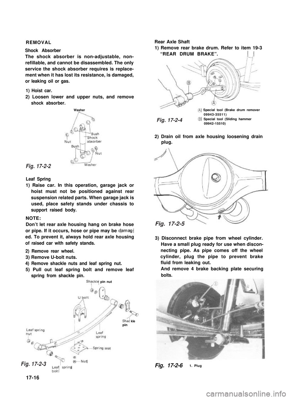
REMOVALRear Axle Shaft
Shock Absorber
The shock absorber is non-adjustable, non-
refillable, and cannot be disassembled. The only
service the shock absorber requires is replace-
ment when it has lost its resistance, is damaged,
or leaking oil or gas.
1) Remove rear brake drum. Refer to item 19-3
“REAR DRUM BRAKE”.I /
1) Hoist car.
2) Loosen lower and upper nuts, and remove
shock absorber.
Washer@ Special tool (Brake drum remover09943-35511)
Leaf Spring
1) Raise car. In this operation, garage jack or
hoist must not be positioned against rear
suspension related parts. When garage jack is
used, place safety stands under chassis to
support raised body.
NOTE:
Don’t let rear axle housing hang on brake hose
or pipe. If it occurs, hose or pipe may be d,amag-
ed. To prevent it, always hold rear axle housing
of raised car with safety stands.
2) Remove rear wheel.
3) Remove U-bolt nuts.
4) Remove shackle nuts and leaf spring nut.
5) Pull out leaf spring bolt and remove leaf
spring from shackle pin.
ShTckle pin nut
Sha’, klepin
@Special tool (Sliding hammer09942-15510)
2) Drain oil from axle housing loosening drain
plug.
3) Disconnect brake pipe from wheel cylinder.
Have a small plug ready for use when discon-
necting pipe. As pipe comes off the wheel
cylinder, plug the pipe to prevent brake
fluid from leaking out.
And remove 4 brake backing plate securing
bolts.
*Nut
;-; wring
17-16
Fig. 17-2-61. Plug
Fig. 17-2-2
Fig. 17-2-3
Fig. 17-2-4
Fig. 17-2-5
Page 351 of 962
4) Using special tools indicated below, draw out
each axle shaft with brake backing plate.
Fig. 17-2-7 @ Special Tool (Rear Axle
Remover 09922-66010)
@I Special Tool (Sliding Hammer
09942-15510)
Rear axle shaft that was drawn out.
Fig. 17-2-8
5) In order to remove the retainer ring from the
shaft, grind with a grinder two parts of the
bearing retainer ring as illustrated till it
becomes thin.
Rear wheel bearingretainer ring
Rear axle shaft
Break with a chisel the thin
ring, and it can be removed.
n
ground retainer
6) Using special tools (C and D), remove bear-
ing from shaft and then remove brake back
plate.
CAUTION:
Be careful not to go so far as to grind the
shaft.
Universal pulley09927-l 8410
Bearing remover(09921-57810)
17-17
Fig. 17-2-11
Fig. 17-2-10
Fig. 17-2-9
Page 354 of 962

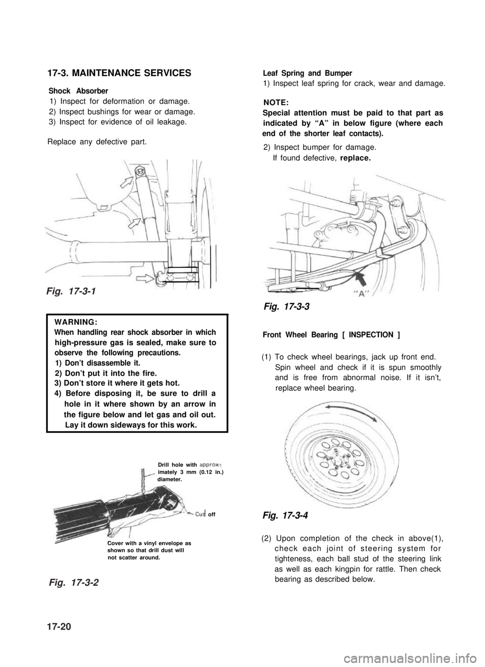
17-3. MAINTENANCE SERVICES
Shock Absorber
1) Inspect for deformation or damage.
2) Inspect bushings for wear or damage.
3) Inspect for evidence of oil leakage.
Replace any defective part.
WARNING:
When handling rear shock absorber in which
high-pressure gas is sealed, make sure to
observe the following precautions.
1) Don’t disassemble it.
2) Don’t put it into the fire.
3) Don’t store it where it gets hot.
4) Before disposing it, be sure to drill a
hole in it where shown by an arrow in
the figure below and let gas and oil out.
Lay it down sideways for this work.
Drill hole with approx-imately 3 mm (0.12 in.)diameter.
‘-cut off
Cover with a vinyl envelope asshown so that drill dust willnot scatter around.
Leaf Spring and Bumper
1) Inspect leaf spring for crack, wear and damage.
NOTE:
Special attention must be paid to that part as
indicated by “A” in below figure (where each
end of the shorter leaf contacts).
2) Inspect bumper for damage.
If found defective, replace.
Fig. 17-3-3
Front Wheel Bearing [ INSPECTION ]
(1) To check wheel bearings, jack up front end.
Spin wheel and check if it is spun smoothly
and is free from abnormal noise. If it isn’t,
replace wheel bearing.
Fig. 17-3-4
(2) Upon completion of the check in above(1),
check each joint of steering system for
tighteness, each ball stud of the steering link
as well as each kingpin for rattle. Then check
bearing as described below.
Fig. 17-3-1
Fig. 17-3-2
17-20