1987 SUZUKI GRAND VITARA wheel
[x] Cancel search: wheelPage 143 of 962

3) Reinstall carburetor following normal service
procedures.
Connect emission control system hoses and
lead wires. Make specified play on accelerator
cable and refill cooling system.
4) Place transaxle gear shift lever in “Neutral”,
set parking brake and block drive wheels.
5) Start engine, and warm it up to normal
operating temperature, stop engine.
6) Be sure to check the following before idle
mixture adjustment.
l Fuel level is within round mark at the
center of level gauge.
l Valve lash is checked and adjusted accord-
ing to the maintenance schedule.
l Air cleaner has been properly installed
and is in good condition.
l All accessories (wipers, heater, lights etc)
are out of service.
l Ignition timing is within specification.
l Choke valve opens fully.
l Idle-up actuator does not operate.
7) Check and adjust idle speed to specification
if necessary.
8) Remove seal rubber of duty check coupler
and connect positive terminal of duty
meter to“Blue/Red” wire and negative
terminal to “Black/Green” wire.
9) Run engine at 1,500 - 2,000 r/min for 30
seconds and bring it to idle speed.
10) With engine running at idle speed, adjust idle
mixture adjusting screw slowly in small incre-
ment allowing time for duty to stabilize after
turning screw to obtain duty of 10 - 50.
If duty is too low, back screw out; if too
high, screw it in. After obtaining duty of
10 - 50, recheck idle speed, and adjust if
necessary.
NOTE:
If adjustment can’t be made because duty meter
indicator does not deflect, check feed back
system according to the checking procedure of
system described in section of Emission Control
System.
11) After adjustment, install seal rubber to duty
check coupler and drive in idle mixture
adjusting screw pin.
4-28
Page 174 of 962
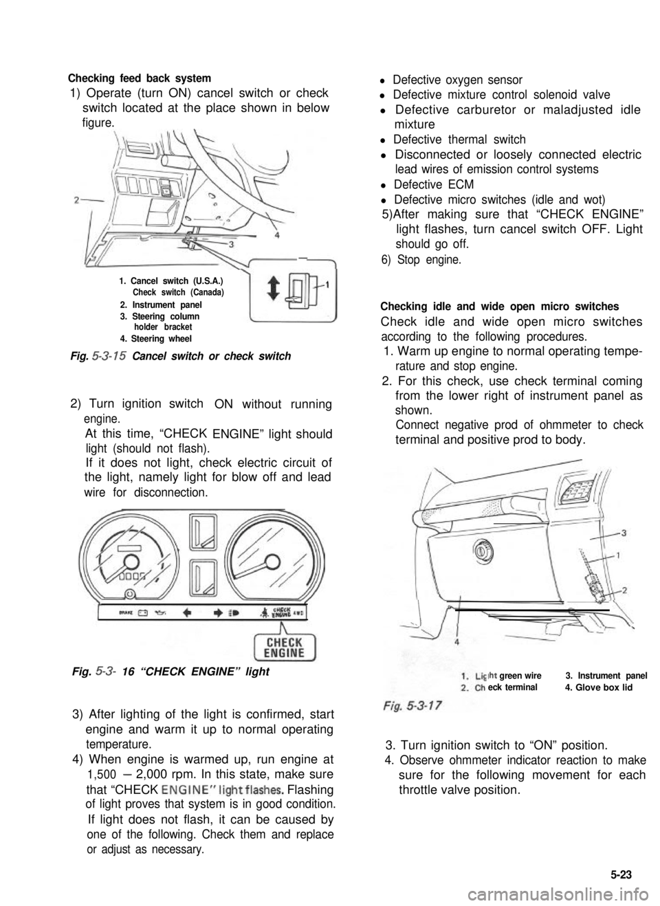
Checking feed back system
1) Operate (turn ON) cancel switch or check
l Defective oxygen sensor
l Defective mixture control solenoid valve
switch located at the place shown in belowl Defective carburetor or maladjusted idle
figure.mixture
-
1. Cancel switch (U.S.A.)Check switch (Canada)
2. Instrument panel
w
$
1
3. Steering columnholder bracket
4. Steering wheel
Fig. 5-3- 15 Cancel switch or check switch
2) Turn ignition switch
engine.
At this time, “CHECK
ON without running
ENGINE” light should
light (should not flash).
If it does not light, check electric circuit of
the light, namely light for blow off and lead
wire for disconnection.
Fig. 5-3- 16 “CHECK ENGINE” light
3) After lighting of the light is confirmed, start
engine and warm it up to normal operating
temperature.
4) When engine is warmed up, run engine at
1,500- 2,000 rpm. In this state, make sure
that “CHECK ENGINE”lightflashes. Flashing
of light proves that system is in good condition.
If light does not flash, it can be caused by
one of the following. Check them and replace
or adjust as necessary.
l Defective thermal switch
l Disconnected or loosely connected electric
lead wires of emission control systems
l Defective ECM
l Defective micro switches (idle and wot)
5)After making sure that “CHECK ENGINE”
light flashes, turn cancel switch OFF. Light
should go off.
6) Stop engine.
Checking idle and wide open micro switches
Check idle and wide open micro switches
according to the following procedures.
1. Warm up engine to normal operating tempe-
rature and stop engine.
2. For this check, use check terminal coming
from the lower right of instrument panel as
shown.
Connect negative prod of ohmmeter to check
terminal and positive prod to body.
Iht green wire
eck terminal
3. Instrument panel
4. Glove box lid
3. Turn ignition switch to “ON” position.
4. Observe ohmmeter indicator reaction to make
sure for the following movement for each
throttle valve position.
5-23
Page 208 of 962
![SUZUKI GRAND VITARA 1987 Service Repair Manual 7-4. REMOVAL AND INSTALLATION
Removal
[Heater and blower motor]
1. Disconnect battery negative cable.
2. Drain cooling system.
WARNING:
To help avoid the danger of being burned, do
not remove the drai SUZUKI GRAND VITARA 1987 Service Repair Manual 7-4. REMOVAL AND INSTALLATION
Removal
[Heater and blower motor]
1. Disconnect battery negative cable.
2. Drain cooling system.
WARNING:
To help avoid the danger of being burned, do
not remove the drai](/manual-img/20/57437/w960_57437-207.png)
7-4. REMOVAL AND INSTALLATION
Removal
[Heater and blower motor]
1. Disconnect battery negative cable.
2. Drain cooling system.
WARNING:
To help avoid the danger of being burned, do
not remove the drain plug and the radiator
cap while the engine and radiator are still hot.
Scalding fluid and steam can be blown out
under pressure if the plug and cap are taken
off too soon.
Fig 7-51. Drain plug2. Radiator
3. Disconnect heater inlet and outlet hoses
from heater unit pipes.
4. Remove instrument panel ass’y with speedo-
meter ass’y as follows.
1) Take off horn pad and remove steering
wheel using special tool @.
2) If equipped with radio and cigarette lighter,
disconnect radio and cigarette lighter lead
wires, and pull out radio case with radio
and cigarette lighter after loosening case
stay screw, and remove radio case bracket.
3) Pull out ashtray and loosen ashtray plate
screws.
4) Disconnect front food opening cable from
lock ass’y.
5) Loosen panel box stay screw and hood
opening cable lock nut on back side of
panel box cover.
6) Disconnect lead wires to control lever at
the coupler and heater control cables.
7) Pull out lever knobs and plate, and loosen
lever case screws.
8) Remove defroster and side ventilator hoses.
9) Disconnect lead wires to speedometer and
switches installed instrument panel at the
couplers.
10) Disconnect speedometer cable from speedo-
meter.
11) Release wire harness clamps installed to
instrument panel.
12) Loosen screws securing instrument panel.
13) Remove instrument panel.
NOTE:
l Before removing, recheck to ascertain all
hoses, wire harness, cables and screws are
disconnected from instrument paneL
l When removing heater lever case which is
fitted in steering column holder, be very
careful not to damage it
5. Remove steering column holder after loosen-
ing front door open stopper screws.
Fig. 7-7Fig. 7-6@ Special tool (Steering wheel
remover 09944-360 10)
7-5
Page 219 of 962
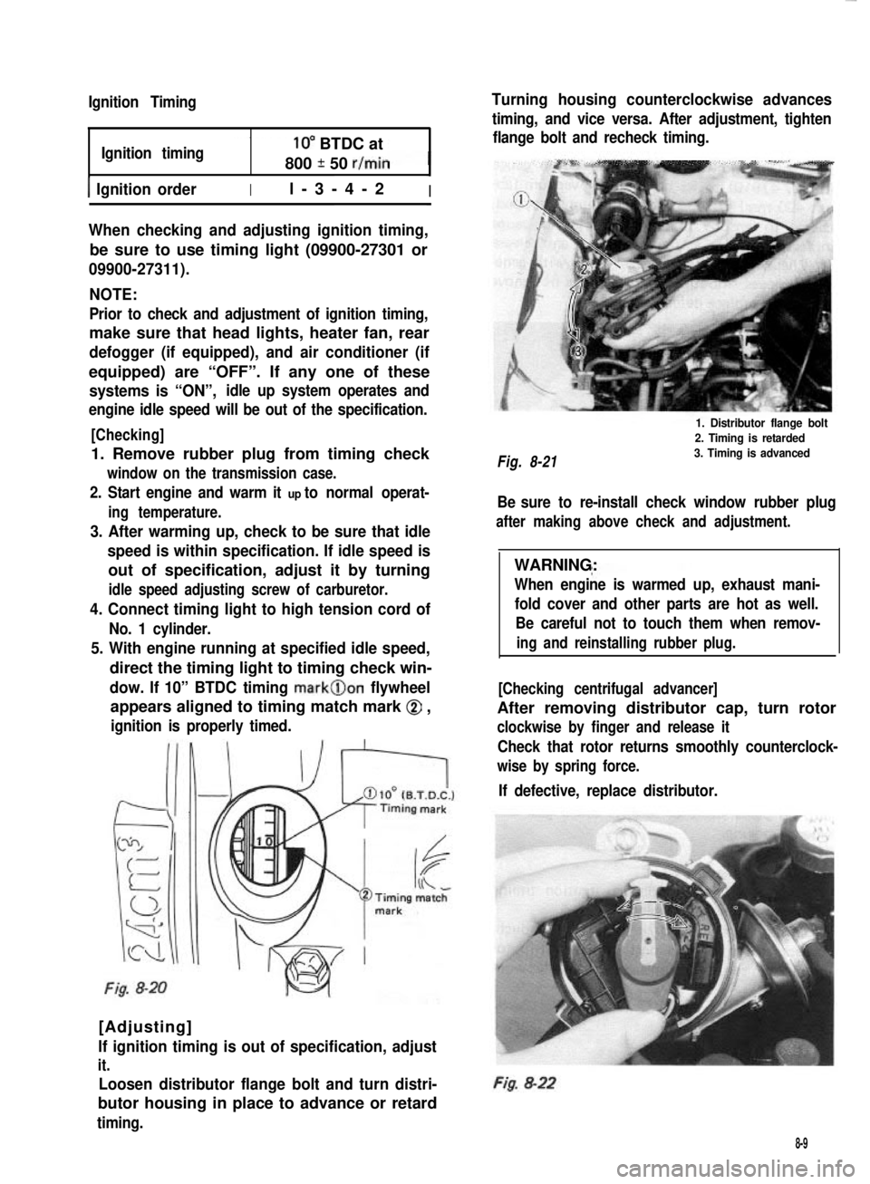
Ignition Timing
Ignition timing10” BTDC at
800 * 50 r/min
1 Ignition orderIl-3-4-2I
When checking and adjusting ignition timing,
be sure to use timing light (09900-27301 or
09900-27311).
NOTE:
Prior to check and adjustment of ignition timing,
make sure that head lights, heater fan, rear
defogger (if equipped), and air conditioner (if
equipped) are “OFF”. If any one of these
systems is “ON”,idle up system operates and
engine idle speed will be out of the specification.
[Checking]
1. Remove rubber plug from timing check
window on the transmission case.
2. Start engine and warm it up to normal operat-
ing temperature.
3. After warming up, check to be sure that idle
speed is within specification. If idle speed is
out of specification, adjust it by turning
idle speed adjusting screw of carburetor.
4. Connect timing light to high tension cord of
No. 1 cylinder.
5. With engine running at specified idle speed,
direct the timing light to timing check win-
dow. If 10” BTDC timing mark@on flywheel
appears aligned to timing match mark @ ,
ignition is properly timed.
Fig. 8-20
[Adjusting]
lf ignition timing is out of specification, adjust
it.
Loosen distributor flange bolt and turn distri-
butor housing in place to advance or retard
timing.
Turning housing counterclockwise advances
timing, and vice versa. After adjustment, tighten
flange bolt and recheck timing.
Fig. 8-21
1. Distributor flange bolt
2. Timing is retarded
3. Timing is advanced
Be sure to re-install check window rubber plug
after making above check and adjustment.
WARNING:
When engine is warmed up, exhaust mani-
fold cover and other parts are hot as well.
Be careful not to touch them when remov-
ing and reinstalling rubber plug.
[Checking centrifugal advancer]
After removing distributor cap, turn rotor
clockwise by finger and release it
Check that rotor returns smoothly counterclock-
wise by spring force.
If defective, replace distributor.
Fig. 8-22
8-9
Page 221 of 962
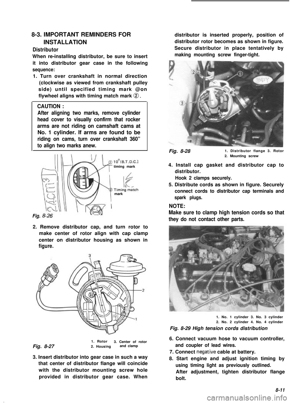
8-3. IMPORTANT REMINDERS FOR
INSTALLATIONDistributor
When re-installing distributor, be sure to insertit into distributor gear case in the following
sequence:
1. Turn over crankshaft in normal direction (clockwise as viewed from crankshaft pulley
side) until specified timing mark @on flywheel aligns with timing match mark
0.
CAUTION :
After aligning two marks, remove cylinder
head cover to visually confirm that rocker
arms are not riding on camshaft cams at
No. 1 cylinder. If arms are found to be
riding on cams, turn over crankshaft 360”
to align two marks anew.
lO’(B.T.D.C.1timing mark
mark
Fig.
2. Remove distributor cap, and turn rotor to make center of rotor align with cap clamp
center on distributor housing as shown in
figure.
1. Rotor
Fig. 8-27 3. Center of rotor
2. Housing and clamp
3. Insert distributor into gear case in such a way that center of distributor flange will coincide
with the distributor mounting screw holeprovided in distributor gear case. When distributor is inserted properly, position of
distributor rotor becomes as shown in figure.
Secure distributor in place tentatively by
making mounting screw finger-tight.
Fig. 8-28 1. Distributor flange 3. Rotor
2. Mounting screw
4. Install cap gasket and distributor cap to
distributor. Hook 2 clamps securely.
5. Distribute cords as shown in figure. Securely
connect cords to distributor cap terminals and
spark plugs.
NOTE:
Make sure to clamp high tension cords so that
they do not contact other parts.
1. No. 1 cylinder 3. No. 3 cylinder
2. No. 2 cylinder 4. No. 4 cylinder
Fig. 8-29 High tension cords distribution
6. Connect vacuum hose to vacuum controller,
and coupler of lead wires.
7. Connect negative cable at battery.
8. Start engine and adjust ignition timing by
using timing light as previously outlined.
After adjustment, tighten distributor flange
bolt.
8-11
Page 223 of 962
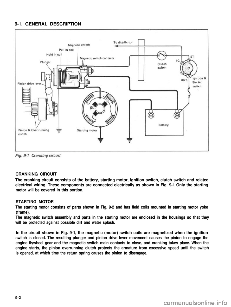
9-1. GENERAL DESCRIPTION
To distributorMagnetic switch
Pull in coil
Hold in coil
I I
Magnetic switch contacts
Plungerhclutch. . . ..i+rh
Pin
h n
Pinion 84 Over running
clutchStarting motor
Fig. 9 1 Cranking circuit
CRANKING CIRCUIT
The cranking circuit consists of the battery, starting motor, ignition switch, clutch switch and related
electrical wiring. These components are connected electrically as shown in Fig. 9-l. Only the starting
motor will be covered in this portion.
STARTING MOTOR
The starting motor consists of parts shown in Fig. 9-2 and has field coils mounted in starting motor yoke
(frame).
The magnetic switch assembly and parts in the starting motor are enclosed in the housings so that they
will be protected against possible dirt and water splash.
In the circuit shown in Fig. 9-1, the magnetic (motor) switch coils are magnetized when the ignition
switch is closed. The resulting plunger and pinion drive lever movement causes the pinion to engage the
engine flywheel gear and the magnetic switch main contacts to close, and cranking takes place. When the
engine starts, the pinion overrunning clutch protects the armature from excessive speed until the switch
is opened, at which time the return spring causes the pinion to disengage.
9-2
Page 247 of 962
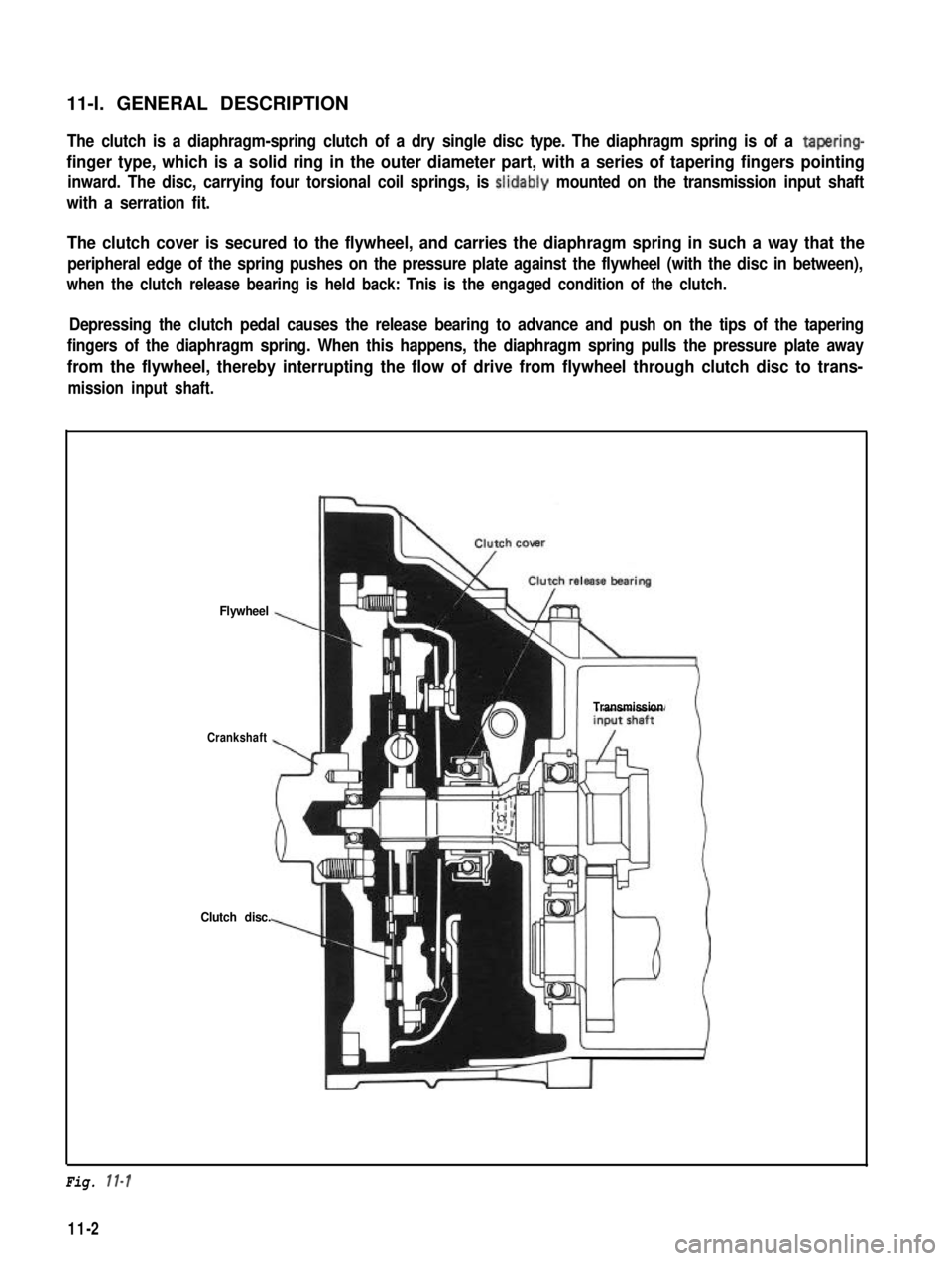
11-l. GENERAL DESCRIPTIONThe clutch is a diaphragm-spring clutch of a dry single disc type. The diaphragm spring is of a tapering-
finger type, which is a solid ring in the outer diameter part, with a series of tapering fingers pointing
inward. The disc, carrying four torsional coil springs, is slidably mounted on the transmission input shaft
with a serration fit.
The clutch cover is secured to the flywheel, and carries the diaphragm spring in such a way that the
peripheral edge of the spring pushes on the pressure plate against the flywheel (with the disc in between),
when the clutch release bearing is held back: Tnis is the engaged condition of the clutch.
Depressing the clutch pedal causes the release bearing to advance and push on the tips of the tapering
fingers of the diaphragm spring. When this happens, the diaphragm spring pulls the pressure plate away
from the flywheel, thereby interrupting the flow of drive from flywheel through clutch disc to trans-
mission input shaft.
Flywheel
Crankshaft
Clutch disc.
Transmission
Fig. 11-l
11-2
Page 249 of 962
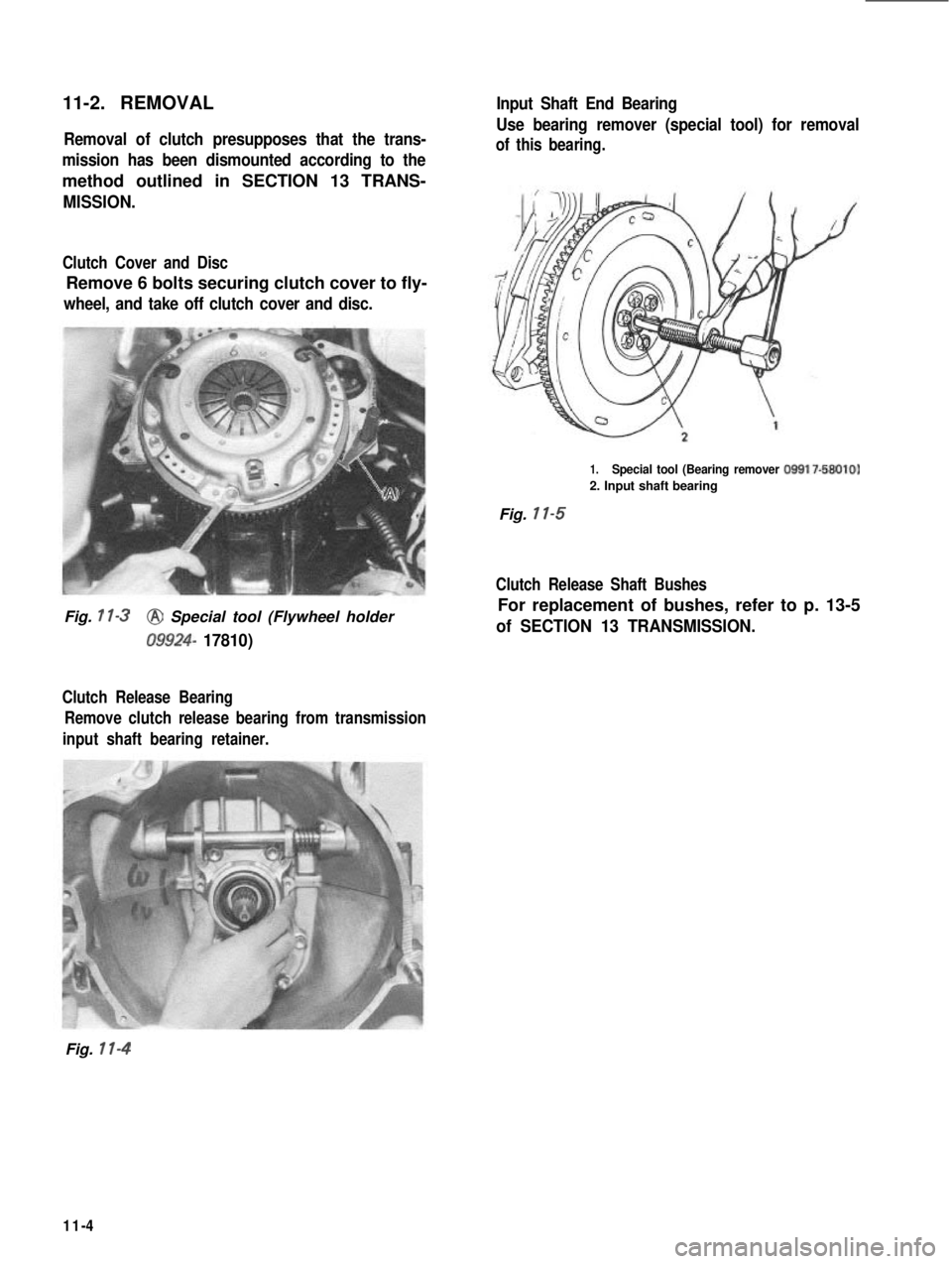
11-2. REMOVALRemoval of clutch presupposes that the trans-
mission has been dismounted according to the
method outlined in SECTION 13 TRANS-
MISSION.
Clutch Cover and Disc
Remove 6 bolts securing clutch cover to fly-
wheel, and take off clutch cover and disc.
Fig. 1 l-3@ Special tool (Flywheel holder
09924- 17810)
Clutch Release Bearing Remove clutch release bearing from transmission
input shaft bearing retainer.
Input Shaft End Bearing
Use bearing remover (special tool) for removal
of this bearing.
1.Special tool (Bearing remover 09917-58010)
2. Input shaft bearing
Fig. 11-5
Clutch Release Shaft Bushes
For replacement of bushes, refer to p. 13-5
of SECTION 13 TRANSMISSION.
Fig. 11-4
11-4