Page 54 of 962
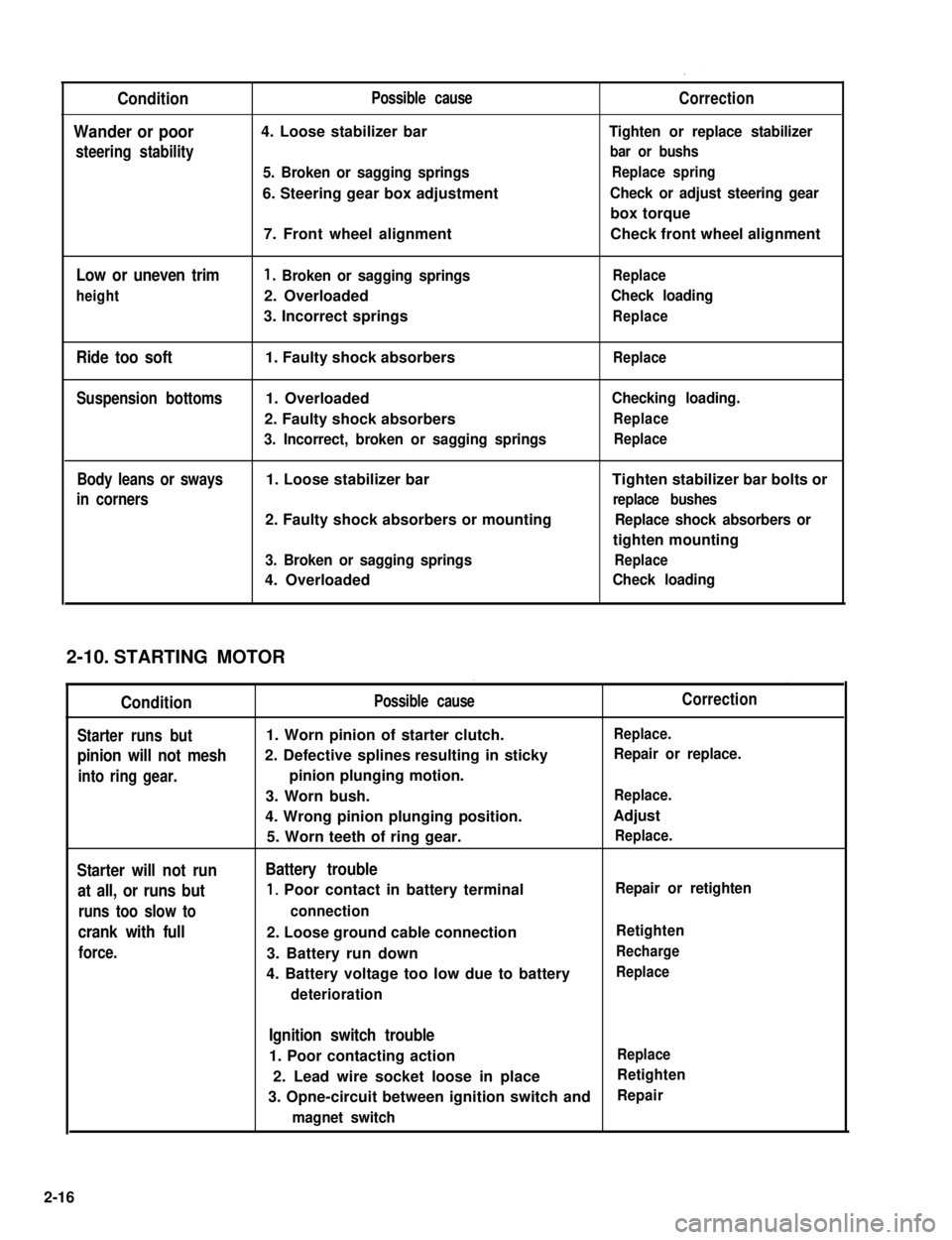
Condition
Wander or poor
steering stability
Low or uneven trim
height
Ride too soft
Suspension bottoms
Body leans or sways
in corners
Possible cause
4. Loose stabilizer bar
5. Broken or sagging springs
6. Steering gear box adjustment
7. Front wheel alignment
1. Broken or sagging springs
2. Overloaded
3. Incorrect springs
1. Faulty shock absorbers
1. Overloaded
2. Faulty shock absorbers
3. Incorrect, broken or sagging springs
1. Loose stabilizer bar
2. Faulty shock absorbers or mounting
3. Broken or sagging springs
4. Overloaded
Correction
Tighten or replace stabilizer
bar or bushs
Replace spring
Check or adjust steering gear
box torque
Check front wheel alignment
Replace
Check loading
Replace
Replace
Checking loading.
Replace
Replace
Tighten stabilizer bar bolts or
replace bushes
Replace shock absorbers or
tighten mounting
Replace
Check loading
STARTING MOTOR
Condition
Starter runs but
pinion will not mesh
into ring gear.
Starter will not run
at all, or runs but
runs too slow to
crank with full
force.
Possible cause
1. Worn pinion of starter clutch.
2. Defective splines resulting in sticky
pinion plunging motion.
3. Worn bush.
4. Wrong pinion plunging position.
5. Worn teeth of ring gear.
Battery trouble
1, Poor contact in battery terminal
connection
2. Loose ground cable connection
3. Battery run down
4. Battery voltage too low due to battery
deterioration
Correction
Replace.
Repair or replace.
Replace.
Adjust
Replace.
Repair or retighten
Retighten
Recharge
Replace
Ignition switch trouble
1. Poor contacting actionReplace
2. Lead wire socket loose in placeRetighten
3. Opne-circuit between ignition switch andRepair
magnet switch
2-10.
2-16
Page 66 of 962
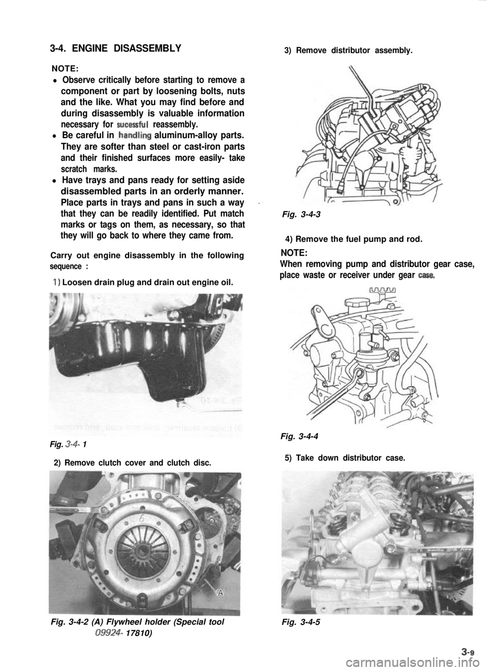
3-4. ENGINE DISASSEMBLY
NOTE:
3) Remove distributor assembly.
l Observe critically before starting to remove a
component or part by loosening bolts, nuts
and the like. What you may find before and
during disassembly is valuable information
necessary for sucessful reassembly.
l Be careful in .handling aluminum-alloy parts.
They are softer than steel or cast-iron parts
and their finished surfaces more easily- take
scratch marks.
l Have trays and pans ready for setting aside
disassembled parts in an orderly manner.
Place parts in trays and pans in such a way_.
that they can be readily identified. Put matchFig. 3-4-3
marks or tags on them, as necessary, so that
they will go back to where they came from.
4) Remove the fuel pump and rod.
Carry out engine disassembly in the following
NOTE:
sequence :When removing pump and distributor gear case,
1) Loosen drain plug and drain out engine oil.place waste or receiver under gear casa.
Fig. 3-4-4Fig. 3-4- 1
2) Remove clutch cover and clutch disc. 5) Take down distributor case.
Fig. 3-4-2 (A) Flywheel holder (Special tool09924-
17810) Fig. 3-4-5
Page 67 of 962
6) Take down alternator and water pump
pulley.
Fig. 3-4,9 (A) Flywheel holder (Special tool
09924-17810)
Fig. 3-4-6
8) Remove outside cover on timing belt.
Fig. 3-4-7
7) Remove crankshaft pulley by removing 49) Loosen tensioner bolt and stud, and remove
pulley bolts, with special tool (A) hitched tobelt from crank timing belt pulley and cam-
flywheel so that crankshaft will not turn.shaft pulley after pushing up tensioner
The crank timing belt pulley bolt at theplate fully by finger as shown in Figure
center needs not to be loosened.3-4-l 1.
1.Crankshaft pulley
Fig. 3-4-8
2. Crankshaft pulley bolt
3.Crank timing belt pulley bolt
Fig. 3-4- 10
1.Timing belt2.Tensioner plate
3.Tensioner boltFig.3-4-114.Tensioner stud
3-10
Page 68 of 962
10) Remove timing belt tensioner, tensioner
plate, and tensioner spring.
11) Remove camshaft timing belt pulley by lock-
ing camshaft (insert general rod into the cam-
shaft hole) as shown below.
13) Remove crankshaft timing belt pulley key.
14) Remove timing belt inside cover.
Fig. 3-4- 14
15) Remove water pump.
1.Wrench2.Camshaft timing belt pulley
3. Timing belt inside cover4.Generalrod
Fig.3412
12) Using flywheel holder (A) (Special tool),
remove crankshaft timing belt pulley bolt,
pulley and timing belt guide with crank-
shaft locked.
Fig. 3-4- 15
16) Remove exhaust manifold cover.
17) Take off exhaust manifold and its gasket.
Fig. 3-4-13
1.Crankshaft timing belt pulley2. Pulley bolt3. Timing belt guide
Fig. 3-4- 16
3-11
Page 71 of 962
b) Remove valve stem oil seal from valve guide,
and then valve spring seat.
NOTE:
Do not reuse oil seal once disassembled. Besure to use new oil seal when assembling.
1. Valve stem oil seal
2. Blade screw driver
Fig. 3-4-283. Valve spring seat
c) Using special tool (F), drive valve guide out from combustion chamber side to valve
spring side (Figure 3-4-29).
NOTE:
Do not reuse valve guide once disassembled.
Be sure to use new valve guide (Oversize) when
assembling.
NOTE:
Place disassembled parts except valve stem seal
and valve guide in order, so that they can be
installed in their original positions.
29) Remove flywheel, using special tool (A)
as shown.
Fig. 3-4-30 (A) Flywheel holder (Special tool
09924- 17810)
30) Remove oil level gauge guide from oil pump.
Fig. 3-4-3 1 (F)
Valve guide remover (Special tool
09916-44511)
Fig. 3-4-29
3-14
Page 87 of 962
Crankshaft Main (Journal) Bearings
General informations:
l Service main bearings are available in standard-
size and 0.25 mm (0.0098 in) undersize, and
each of them has 5 kinds of bearings differ-
ing in tolerance.
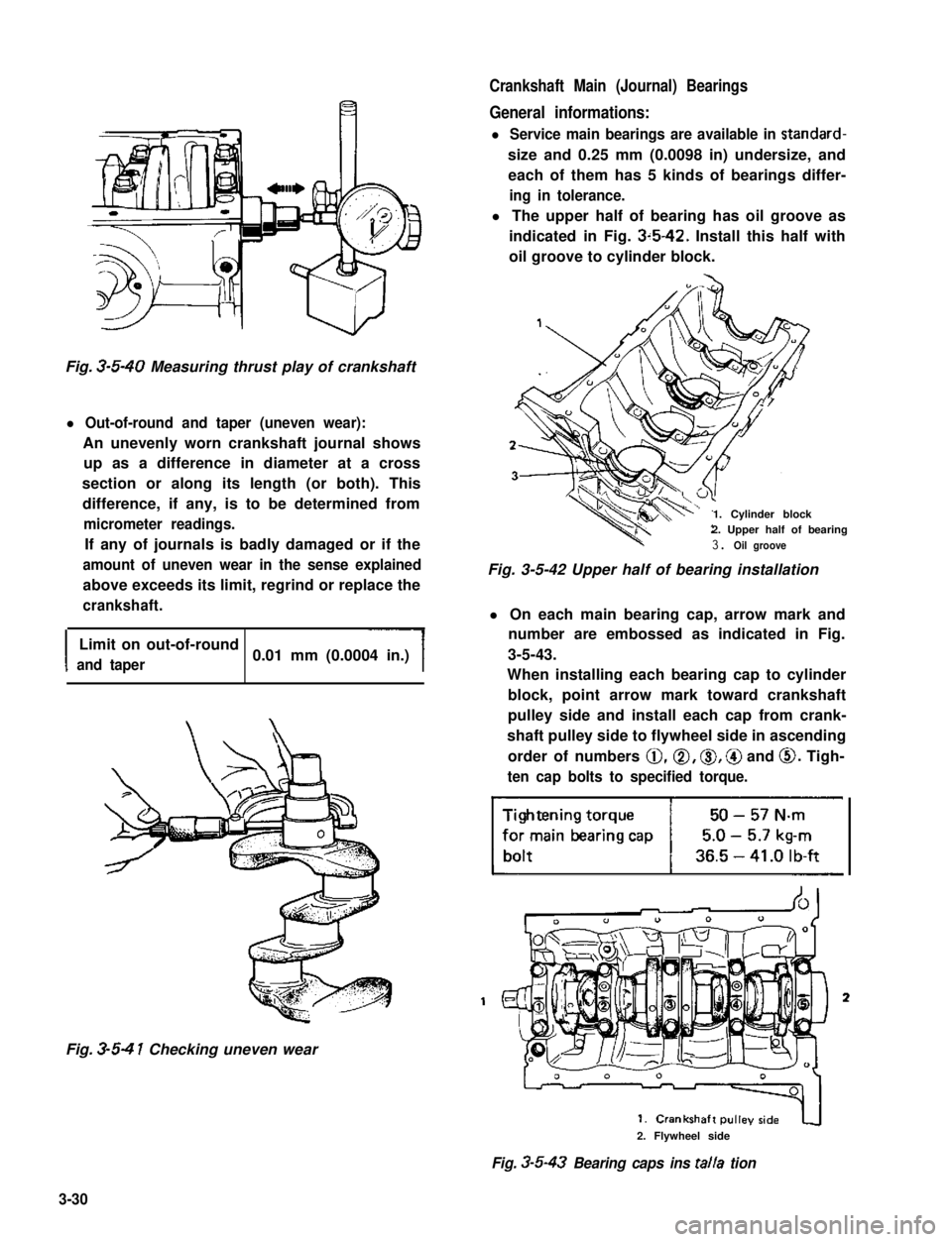
l The upper half of bearing has oil groove as
indicated in Fig. 3~5-42. Install this half with
oil groove to cylinder block.
Fig. 3-5-40 Measuring thrust play of crankshaft
l Out-of-round and taper (uneven wear):
An unevenly worn crankshaft journal shows
up as a difference in diameter at a cross
section or along its length (or both). This
difference, if any, is to be determined from
micrometer readings.
If any of journals is badly damaged or if the
amount of uneven wear in the sense explained
above exceeds its limit, regrind or replace the
crankshaft.
I
Limit on out-of-round
and taper0.01 mm (0.0004 in.)
Fig. 3-5-4 1 Checking uneven wear
1. Cylinder block2. Upper half of bearing
3. Oil groove
Fig. 3-5-42 Upper half of bearing installation
l On each main bearing cap, arrow mark and
number are embossed as indicated in Fig.
3-5-43.
When installing each bearing cap to cylinder
block, point arrow mark toward crankshaft
pulley side and install each cap from crank-
shaft pulley side to flywheel side in ascending
order of numbers @,a, 0, @ and 0. Tigh-
ten cap bolts to specified torque.
3
2. Flywheel side
Fig. 3-5-43 Bearing caps ins talla tion
3-30
Page 91 of 962
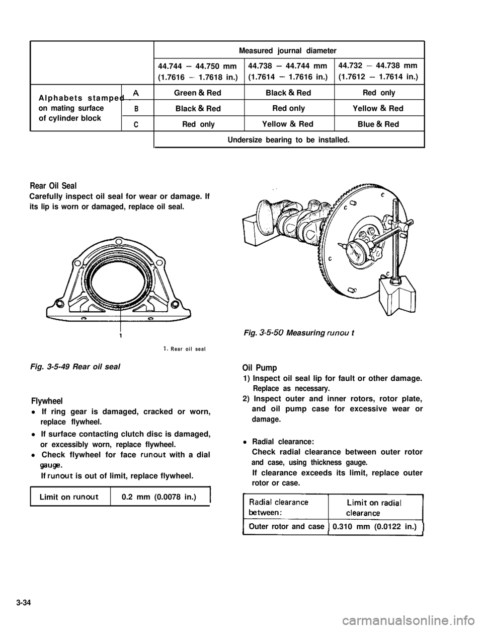
Measured journal diameter
44.744 - 44.750 mm44.738 - 44.744 mm44.732 - 44.738 mm
(1.7616 - 1.7618 in.)(1.7614 - 1.7616 in.)(1.7612 - 1.7614 in.)
Alphabets stamped I AGreen & RedBlack & RedRed only
on mating surfaceBBlack & RedRed onlyYellow & Red
of cylinder blockCRed onlyYellow & RedBlue & Red
Undersize bearing to be installed.
Rear Oil Seal
Carefully inspect oil seal for wear or damage. If
its lip is worn or damaged, replace oil seal.
1. Rear oil seal
Fig. 3-5-49 Rear oil sealOil Pump
Flywheel
l If ring gear is damaged, cracked or worn,
replace flywheel.
l If surface contacting clutch disc is damaged,
or excessibly worn, replace flywheel.
l Check flywheel for face runout with a dial
wge.
If runout is out of limit, replace flywheel.
Limit on runout0.2 mm (0.0078 in.)
Fig. 3-5-50 Measuring runou t
1) Inspect oil seal lip for fault or other damage.
Replace as necessary.
2) Inspect outer and inner rotors, rotor plate,
and oil pump case for excessive wear or
damage.
l Radial clearance:
Check radial clearance between outer rotor
and case, using thickness gauge.
If clearance exceeds its limit, replace outer
rotor or case.
Outer rotor and case0.310 mm (0.0122 in.)
3-34
Page 98 of 962
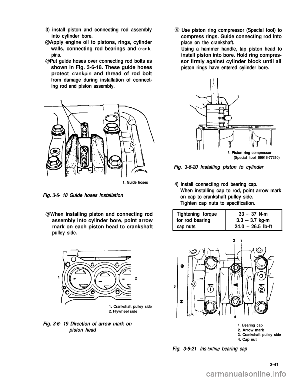
3) install piston and connecting rod assembly
into cylinder bore.
@Apply engine oil to pistons, rings, cylinder
walls, connecting rod bearings and crank-
pins.
@Put guide hoses over connecting rod bolts as
shown in Fig. 3-6-18. These guide hoses
protect crankpin and thread of rod bolt
from damage during installation of connect-
ing rod and piston assembly.
1. Guide hoses
Fig. 3-6- 18 Guide hoses installation
@When installing piston and connecting rod
assembly into cylinder bore, point arrow
mark on each piston head to crankshaft
pulley side.
1. Crankshaft pulley side
2. Flywheel side
Fig. 3-6- 19 Direction of arrow mark on
piston head
@ Use piston ring compressor (Special tool) to
compress rings. Guide connecting rod into
place on the crankshaft.
Using a hammer handle, tap piston head to
install piston into bore. Hold ring compres-
sor firmly against cylinder block until all
piston rings have entered cylinder bore.
1. Piston ring compressor
(Special tool 09916-77310)
Fig. 3-6-20 Installing piston to cylinder
4) Install connecting rod bearing cap.
When installing cap to rod, point arrow mark
on cap to crankshaft pulley side.
Tighten cap nuts to specification.
Tightening torque33-37 N-m
for rod bearing3.3-3.7 kg-m
cap nuts24.0-26.5 lb-ft
1. Bearing cap
2. Arrow mark3. Crankshaft pulley side
4. Cap nut
Fig. 3-6-21Ins tailing bearing cap
3-41