Page 363 of 962
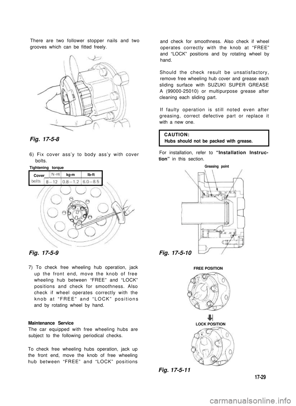
There are two follower stopper nails and two
grooves which can be fitted freely.
Fig. 17-5-8
6) Fix cover ass’y to body ass’y with cover
bolts.
Tightening torque
[ Cover [ N.m 1kg-mlb-ft
Fig. 17-5-9
7) To check free wheeling hub operation, jack
up the front end, move the knob of free
wheeling hub between “FREE” and “LOCK”
positions and check for smoothness. Also
check if wheel operates correctly with the
knob at “FREE” and “LOCK” positions
and by rotating wheel by hand.
Maintenance Service
The car equipped with free wheeling hubs are
subject to the following periodical checks.
To check free wheeling hubs operation, jack up
the front end, move the knob of free wheeling
hub between “FREE” and “LOCK” positions
and check for smoothness. Also check if wheel
operates correctly with the knob at “FREE”
and “LOCK” positions and by rotating wheel by
hand.
Should the check result be unsatisfactory,
remove free wheeling hub cover and grease each
sliding surface with SUZUKI SUPER GREASE
A (99000-25010) or multipurpose grease after
cleaning each sliding part.
If faulty operation is still noted even after
greasing, correct defective part or replace it
with a new one.
CAUTION:
Hubs should not be packed with grease.
For installation, refer to “Installation Instruc-
tion” in this section.
Greasing point
17-5-
FREE POSITION
+LOCK POSITION
Fig. 17-5-11
17-29
Fig. 17-5-10
Page 364 of 962
SECTION 18
STEERING SYSTEM
CONTENTS
18-1.GENERAL DESCRIPTION............................... 18-4
18-2.SPECIFICATIONS AND DATA............................18-4
STEERING GEAR BOX CONSTRUCTION AND OPERATION...18-5
18-4.REMOVAL...........................................18-6
18-5.INSPECTION OF COMPONENTS..........................
CHECKING STEERING COLUMN FOR ACCIDENT DAMAGE.
18-7.IMPORTANT STEPS IN REINSTALLATION..................
18-8.WHEEL ALIGNMENT..................................
18-9.MAINTENANCE SERVICES.............................
18-10. RECOMMENDED TORQUE SPECIFICATIONS..............
NOTE:
All steering system fasteners are important parts in that they could affect the performance
of vital parts and systems, and/or could result in major repair expense. They must be
replaced with one of the same part number or with an equivalent part if replacement
becomes necessary. Do not use a replacement part of lesser quality or substitute design.
Torque values must be used as specified during reassembly to assure proper retention of
this part.
18-1
18-3.
18-9
18-12
18-11
18-16
18-18
18-22
18-6.
Page 372 of 962
18-5. INSPECTION OF COMPONENTS
Steering Gear Box
[Oil level]
Oil surface should be up to the level as shown
in below figures. If not, add prescribed gear oil,
SAE 90.
Right hand steering vehicle
Fig. 18-17
Left hand steering vehicle
I
35mm(1.4 in.)
Fig. 18-18
[Adjustment of worm shaft starting torque]
The steering gear box is provided with adjust-
ing bolt @ which gives preload to sector shaft.
Fig. 18-19 (1)Adjusting bolt
Make an adjustment according to the following
procedure.
1) Check worm shaft to ensure that it is free
from thrust play.
2) Position pitman arm in parallel with worm
shaft as shown below.
(With pitman arm in this position, front
wheel is in straightforward state.)
Worm shaft
Fig. 18-20
Pitman arm
18-9
Page 377 of 962
Steering Column
Steering wheel slip ring
Apply SUZUKI SUPER GREASE A
(99000-25010) all around slip ring
IIbefore fining it. , 1
Steering column seal
\I
Steering column bolt
tightening torqueI
When installing the steering column,
1.
make sure to fit seal rubber in the
rubber
1J
Steering column nut
tightening torque
11 - 17N.m
1.1 - 1.7 kg-m
(8.0 - 12.0 lb-ft)
Fig. 18-30
position as illustrated
18-14
Page 379 of 962
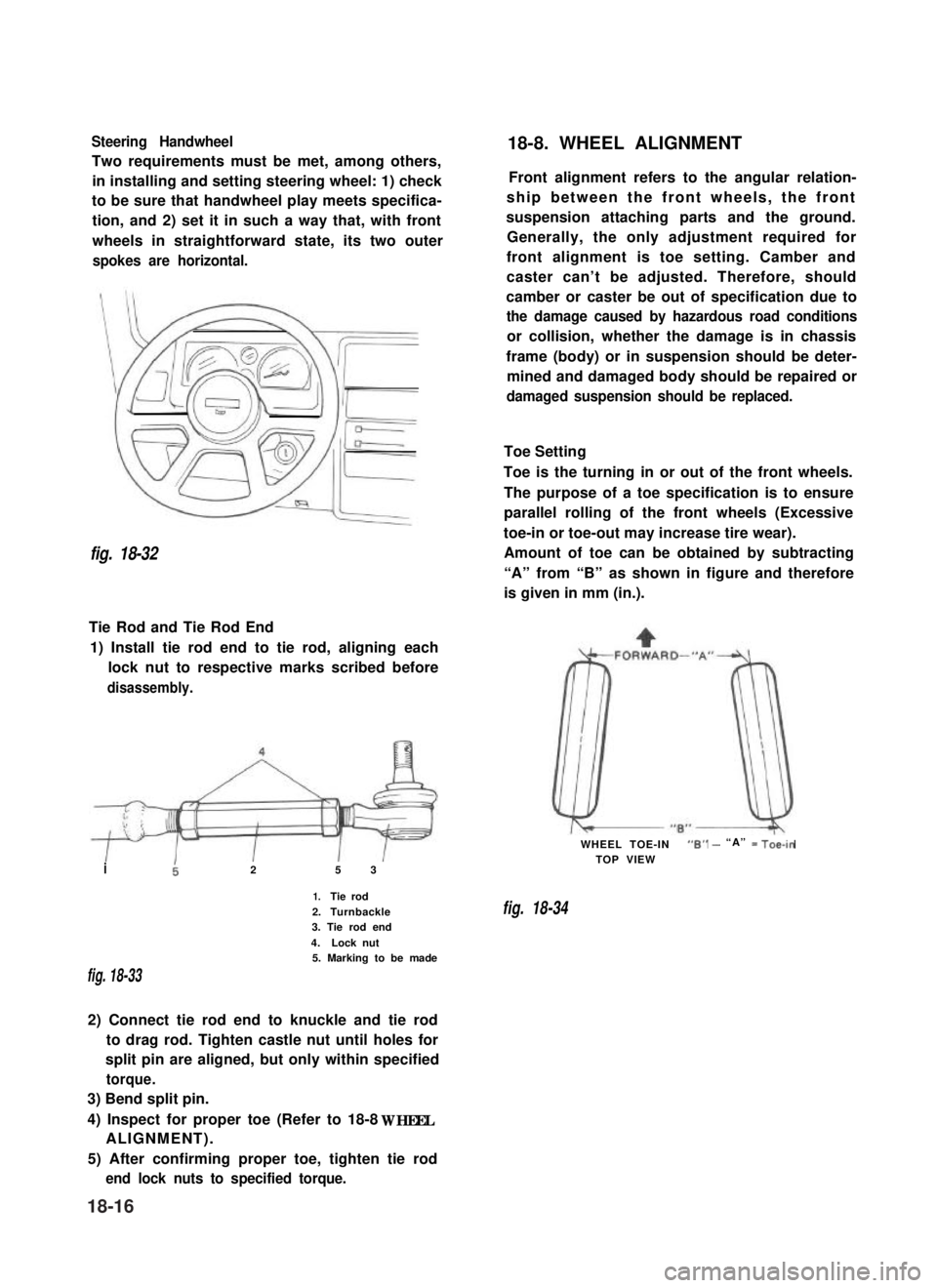
Steering Handwheel
Two requirements must be met, among others,
in installing and setting steering wheel: 1) check
to be sure that handwheel play meets specifica-
tion, and 2) set it in such a way that, with front
wheels in straightforward state, its two outer
spokes are horizontal.
fig. 18-32
Tie Rod and Tie Rod End
1) Install tie rod end to tie rod, aligning each
lock nut to respective marks scribed before
disassembly.
i25 3
1.Tie rod
2.Turnbackle3. Tie rod end
4.Lock nut5. Marking to be made
fig. 18-33
2) Connect tie rod end to knuckle and tie rod
to drag rod. Tighten castle nut until holes for
split pin are aligned, but only within specified
torque.
3) Bend split pin.
4) Inspect for proper toe (Refer to 18-8 WHEEL
ALIGNMENT).
5) After confirming proper toe, tighten tie rod
end lock nuts to specified torque.
18-8. WHEEL ALIGNMENT
Front alignment refers to the angular relation-
ship between the front wheels, the front
suspension attaching parts and the ground.
Generally, the only adjustment required for
front alignment is toe setting. Camber and
caster can’t be adjusted. Therefore, should
camber or caster be out of specification due to
the damage caused by hazardous road conditions
or collision, whether the damage is in chassis
frame (body) or in suspension should be deter-
mined and damaged body should be repaired or
damaged suspension should be replaced.
Toe Setting
Toe is the turning in or out of the front wheels.
The purpose of a toe specification is to ensure
parallel rolling of the front wheels (Excessive
toe-in or toe-out may increase tire wear).
Amount of toe can be obtained by subtracting
“A” from “B” as shown in figure and therefore
is given in mm (in.).
WHEEL TOE-IN“6” - “A” = Toe-in
TOP VIEW
fig. 18-34
18-16
Page 380 of 962
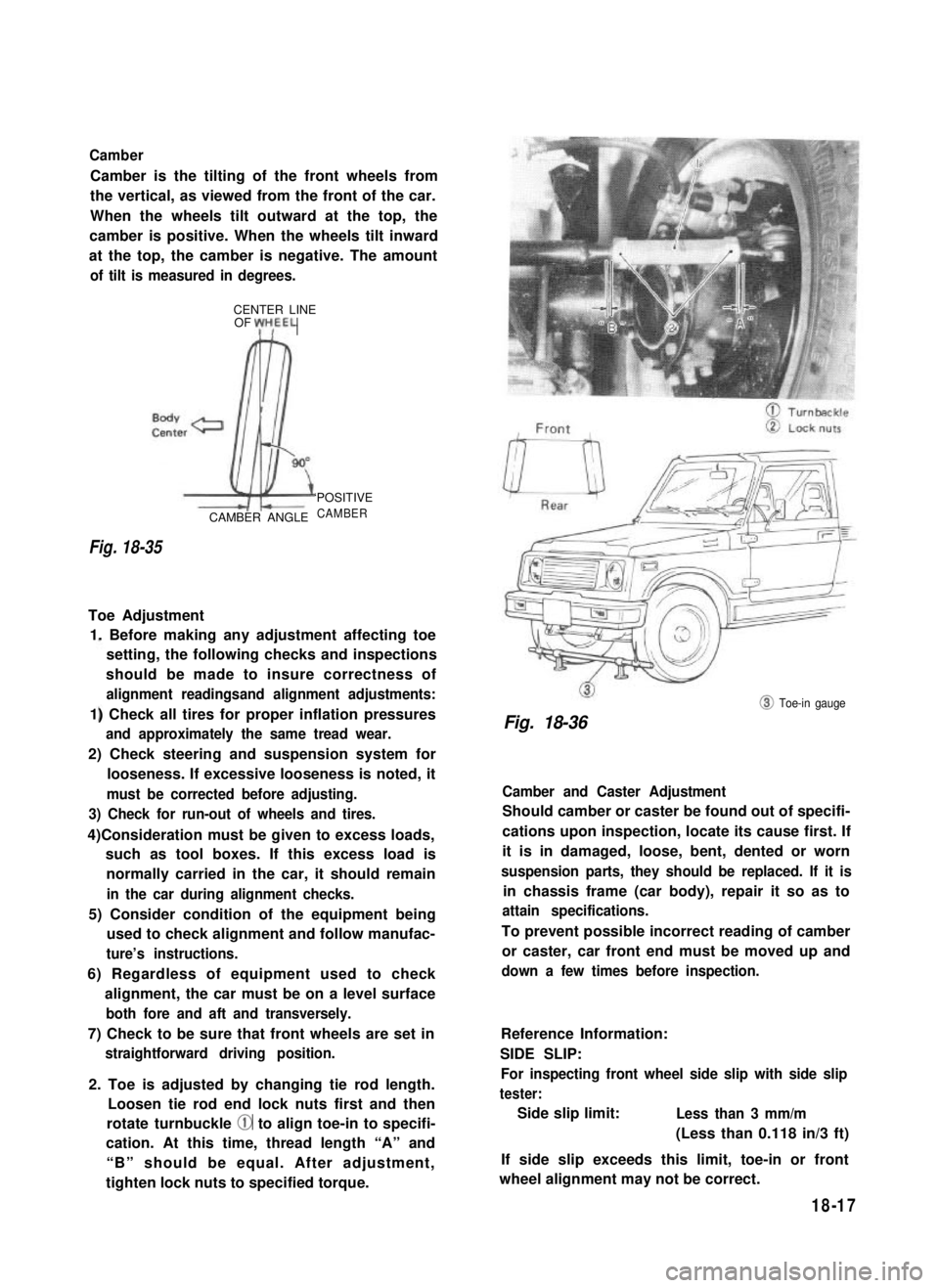
Camber
Camber is the tilting of the front wheels from
the vertical, as viewed from the front of the car.
When the wheels tilt outward at the top, the
camber is positive. When the wheels tilt inward
at the top, the camber is negative. The amount
of tilt is measured in degrees.
CENTER LINEOF yH,EEL
Fig. 18-35
CAMBER ANGLE
‘POSITIVE
CAMBER
Toe Adjustment
1. Before making any adjustment affecting toe
setting, the following checks and inspections
should be made to insure correctness of
alignment readingsand alignment adjustments:
1) Check all tires for proper inflation pressures
and approximately the same tread wear.
2) Check steering and suspension system for
looseness. If excessive looseness is noted, it
must be corrected before adjusting.
3) Check for run-out of wheels and tires.
4)Consideration must be given to excess loads,
such as tool boxes. If this excess load is
normally carried in the car, it should remain
in the car during alignment checks.
5) Consider condition of the equipment being
used to check alignment and follow manufac-
ture’s instructions.
6) Regardless of equipment used to check
alignment, the car must be on a level surface
both fore and aft and transversely.
7) Check to be sure that front wheels are set in
straightforward driving position.
2. Toe is adjusted by changing tie rod length.
Loosen tie rod end lock nuts first and then
rotate turnbuckle @ to align toe-in to specifi-
cation. At this time, thread length “A” and
“B” should be equal. After adjustment,
tighten lock nuts to specified torque.
@ Toe-in gauge
Fig. 18-36
Camber and Caster Adjustment
Should camber or caster be found out of specifi-
cations upon inspection, locate its cause first. If
it is in damaged, loose, bent, dented or worn
suspension parts, they should be replaced. If it is
in chassis frame (car body), repair it so as to
attain specifications.
To prevent possible incorrect reading of camber
or caster, car front end must be moved up and
down a few times before inspection.
Reference Information:
SIDE SLIP:
For inspecting front wheel side slip with side slip
tester:
Side slip limit:Less than 3 mm/m
(Less than 0.118 in/3 ft)
If side slip exceeds this limit, toe-in or front
wheel alignment may not be correct.
18-17
Page 381 of 962
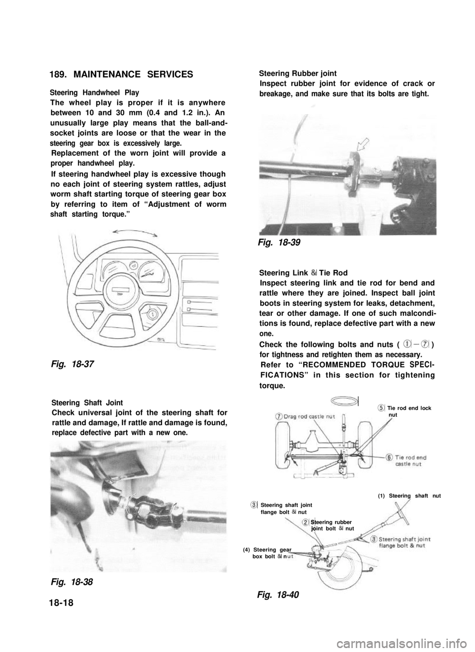
189. MAINTENANCE SERVICES
Steering Handwheel Play
The wheel play is proper if it is anywhere
between 10 and 30 mm (0.4 and 1.2 in.). An
unusually large play means that the ball-and-
socket joints are loose or that the wear in the
steering gear box is excessively large.
Replacement of the worn joint will provide a
proper handwheel play.
If steering handwheel play is excessive though
no each joint of steering system rattles, adjust
worm shaft starting torque of steering gear box
by referring to item of “Adjustment of worm
shaft starting torque.”
Fig. 18-37
Steering Shaft Joint
Check universal joint of the steering shaft for
rattle and damage, If rattle and damage is found,
replace defective part with a new one.
0
Steering Rubber joint
Inspect rubber joint for evidence of crack or
breakage, and make sure that its bolts are tight.
Fig. 18-39
Steering Link & Tie Rod
Inspect steering link and tie rod for bend and
rattle where they are joined. Inspect ball joint
boots in steering system for leaks, detachment,
tear or other damage. If one of such malcondi-
tions is found, replace defective part with a new
one.
Check the following bolts and nuts ( @ - 0 )
for tightness and retighten them as necessary.
Refer to “RECOMMENDED TORQUE SPECI-
FICATIONS” in this section for tightening
torque.
a@ Tie rod end locknut
(1) Steering shaft nut
Steering shaft jointflange bolt 84 nut
\,
@ Steering rubberjoint bolt & nut
(4) Steering gearbox bolt & n
Fig. 18-38
Fig. 18-40
18-18
Page 382 of 962
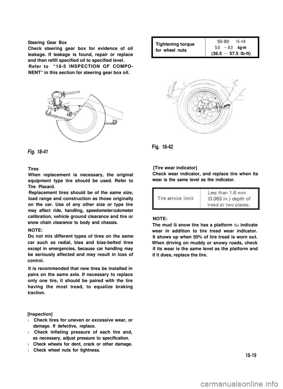
Steering Gear Box
Check steering gear box for evidence of oil
leakage. If leakage is found, repair or replace
and then refill specified oil to specified level.
Refer to“18-5 INSPECTION OF COMPO-
NENT” in this section for steering gear box oil.
Tightening torque
for wheel nuts
50-80 N.m
5.0 - 8.0 kg-m
(36.5 - 57.5 lb-ft)
Fig. 18-42
Fig. 18-41
Tires[Tire wear indicator]
When replacement is necessary, the original
equipment type tire should be used. Refer to
Tire Placard.
Check wear indicator, and replace tire when its
wear is the same level as the indicator.
Replacement tires should be of the same size,
load range and construction as those originally
on the car. Use of any other size or type tire
may affect ride, handling, speedometer/odometer
calibration, vehicle ground clearance and tire or
snow chain clearance to body and chassis.
NOTE:
NOTE:
Do not mix different types of tires on the same
car such as radial, bias and bias-belted tires
except in emergencies, because car handling may
be seriously affected and may result in loss of
control.
The mud & snow tire has a platform ttr indicate
wear in addition to tire tread wear indicator.
It shows up when 50% of tire tread is worn out.
When driving on muddy or snowy roads, check
if its wear is the same level as the platform and
if it does, replace the tire.
It is recommended that new tires be installed in
pairs on the same axle. If necessary to replace
only one tire, it should be paired with the tire
having the most tread, to equalize braking
traction.
[Inspection]
l Check tires for uneven or excessive wear, or
damage. If defective, replace.
l Check inflating pressure of each tire and,
as necessary, adjust pressure to specification.
l Check wheels for dent, crack or other damage.
l Check wheel nuts for tightness.
18-19