Page 333 of 962
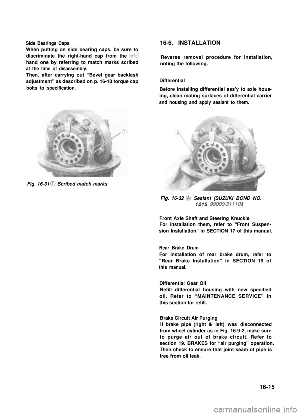
Side Bearings Caps
When putting on side bearing caps, be sure to
discriminate the right-hand cap from the left-
hand one by referring to match marks scribed
at the time of disassembly.
Then, after carrying out “Bevel gear backlash
adjustment” as described on p. 16-10 torque cap
bolts to specification.
16-6. INSTALLATION
Reverse removal procedure for installation,
noting the following.
Differential
Before installing differential ass’y to axle hous-
ing, clean mating surfaces of differential carrier
and housing and apply sealant to them.
Fig. 16-31 0 Scribed match marks
Fig. 16-32 @ Sealant (SUZUKI BOND NO.
1215 99000-31110)
Front Axle Shaft and Steering Knuckle
For installation them, refer to “Front Suspen-
sion Installation” in SECTION 17 of this manual.
Rear Brake Drum
For installation of rear brake drum, refer to
“Rear Brake Installation” in SECTION 19 of
this manual.
Differential Gear Oil
Refill differential housing with new specified
oil. Refer to “MAINTENANCE SERVICE” in
this section for refill.
Brake Circuit Air Purging
If brake pipe (right & left) was disconnected
from wheel cylinder as in Fig. 16-9-2, make sure
to purge air out of brake circuit. Refer to
section 19. BRAKES for “air purging" operation.
Then check to ensure that joint seam of pipe is
free from oil leak.
16-15
Page 335 of 962
SECTION 17
SUSPENSION
CONTENTS
17-1. FRONT SUSPENSION. . . . . . . . . . . . . . . . . . . . . . . . . . . . . . . . . . . . . . 17-2
17-2. REAR SUSPENSION . . . . . . . . . . . . . . . . . . . . . . . . . . . . . . . . . . . . . . 17-15
17-3. MAINTENANCE SERVICES.. . . . . . . . . . . . . . . . . . . . . . . . . . . . . . . 17-20
17-4. RECOMMENDED TORQUE SPECIFICATIONS.. . . . . . . . . . . . . . . . 17-26
17-5. FRONT FREE WHEELING HUB (OPTIONAL) . . . . . . . . . . . . . . . . . 17-27
NOTE:
l All suspension fasteners are an important attaching part in that it could affect the
performance of vital parts and systems, and/or could result in major repair expense.
They must be replaced with one of the same part number or with an equivalent part if
replacement becomes necessary. Do not use a replacement part of lesser quality or
substitute design. Torque values must be used as specified during reassembly to assure
proper retention of this part.
l Never attempt to heat, quench or straighten any suspension part. Replace it with a new
part, or damage to the part may result.
l The leaf spring number or shape shown in this manual may differ from the car being
actually serviced, depending on specification.
17-1
Page 355 of 962
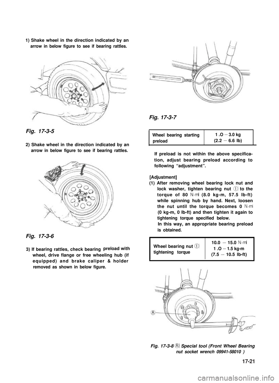
1) Shake wheel in the direction indicated by an
arrow in below figure to see if bearing rattles.
Fig. 17-3-5
2) Shake wheel in the direction indicated by an
arrow in below figure to see if bearing rattles.
Fig. 17-3-6
3) If bearing rattles, check bearingpreload with
wheel, drive flange or free wheeling hub (if
equipped) and brake caliper & holder
removed as shown in below figure.
Fig. 17-3-7
Wheel bearing starting1 .O - 3.0 kg
preload(2.2 - 6.6 lb)
If preload is not within the above specifica-
tion, adjust bearing preload according to
following “adjustment”.
[Adjustment]
(1) After removing wheel bearing lock nut and
lock washer, tighten bearing nut @ to the
torque of 80 N-m (8.0 kg-m, 57.5 lb-ft)
while spinning hub by hand. Next, loosen
the nut until the torque becomes 0 N.m
(0 kg-m, 0 lb-ft) and then tighten it again to
tightening torque specified below.
In this way, an appropriate bearing preload
is obtained.
Wheel bearing nut @
tightening torque
10.0 - 15.0 N-m
1 .O - 1.5 kg-m
(7.5 - 10.5 lb-ft)
Fig. 17-3-8 @ Special tool (Front Wheel Bearing
nut socket wrench 09941-58010 )
17-21
Page 356 of 962
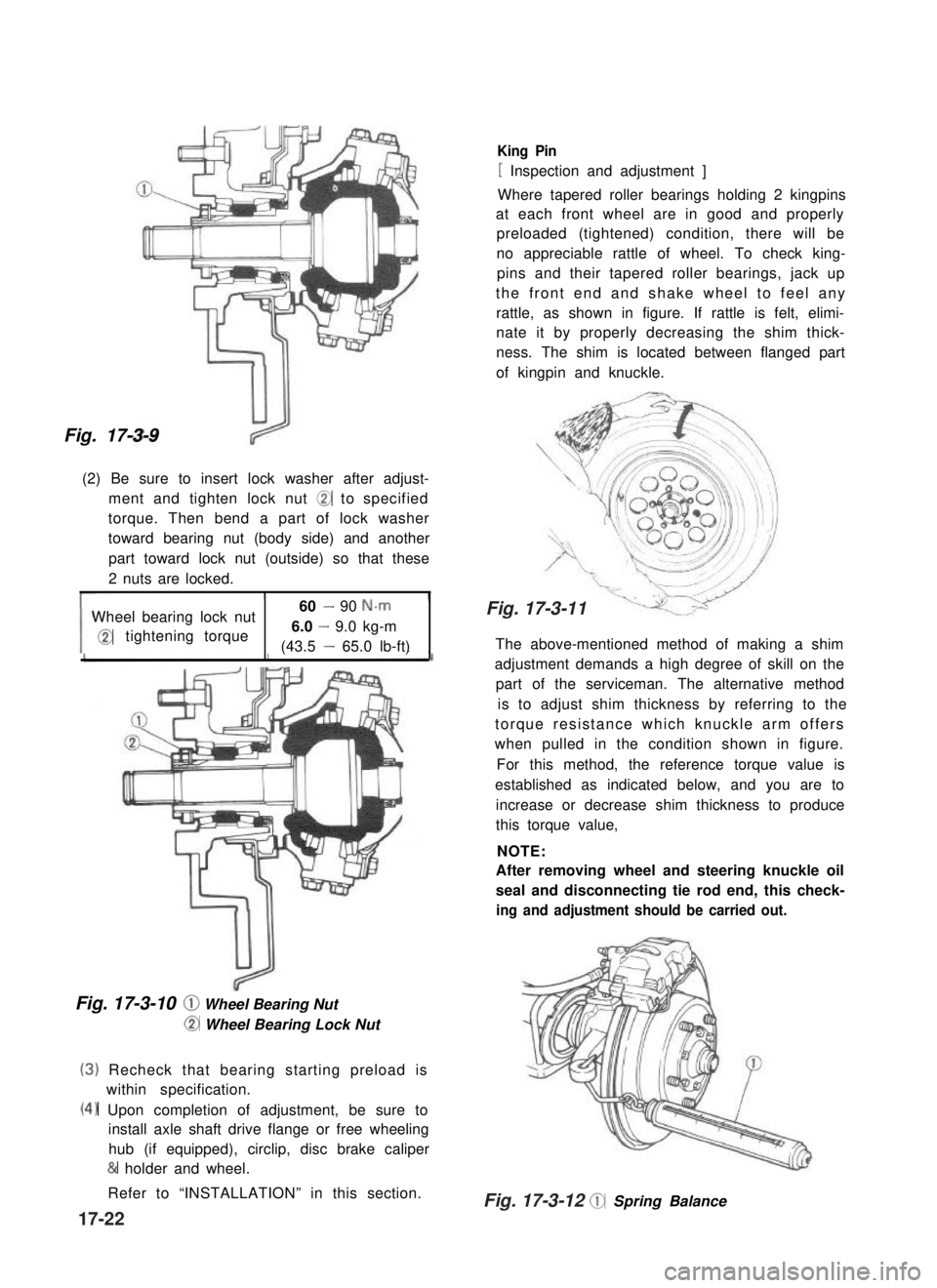
Fig. 17-3-9
(2) Be sure to insert lock washer after adjust-
ment and tighten lock nut @ to specified
torque. Then bend a part of lock washer
toward bearing nut (body side) and another
part toward lock nut (outside) so that these
2 nuts are locked.
Wheel bearing lock nut60 - 90 N-m
@tightening torque6.0 - 9.0 kg-m
(43.5 - 65.0 lb-ft)
Fig. 17-3-10 @ Wheel Bearing Nut
@ Wheel Bearing Lock Nut
(3)
(4)
Recheck that bearing starting preload is
within specification.
Upon completion of adjustment, be sure to
install axle shaft drive flange or free wheeling
hub (if equipped), circlip, disc brake caliper
& holder and wheel.
Refer to “INSTALLATION” in this section.
King Pin
[ Inspection and adjustment ]
Where tapered roller bearings holding 2 kingpins
at each front wheel are in good and properly
preloaded (tightened) condition, there will be
no appreciable rattle of wheel. To check king-
pins and their tapered roller bearings, jack up
the front end and shake wheel to feel any
rattle, as shown in figure. If rattle is felt, elimi-
nate it by properly decreasing the shim thick-
ness. The shim is located between flanged part
of kingpin and knuckle.
The above-mentioned method of making a shim
adjustment demands a high degree of skill on the
part of the serviceman. The alternative method
is to adjust shim thickness by referring to the
torque resistance which knuckle arm offers
when pulled in the condition shown in figure.
For this method, the reference torque value is
established as indicated below, and you are to
increase or decrease shim thickness to produce
this torque value,
NOTE:
After removing wheel and steering knuckle oil
seal and disconnecting tie rod end, this check-
ing and adjustment shouId be carried out.
@ Spring Balance
17-22
Fig. 17-3-12
Fig. 17-3-11
Page 357 of 962
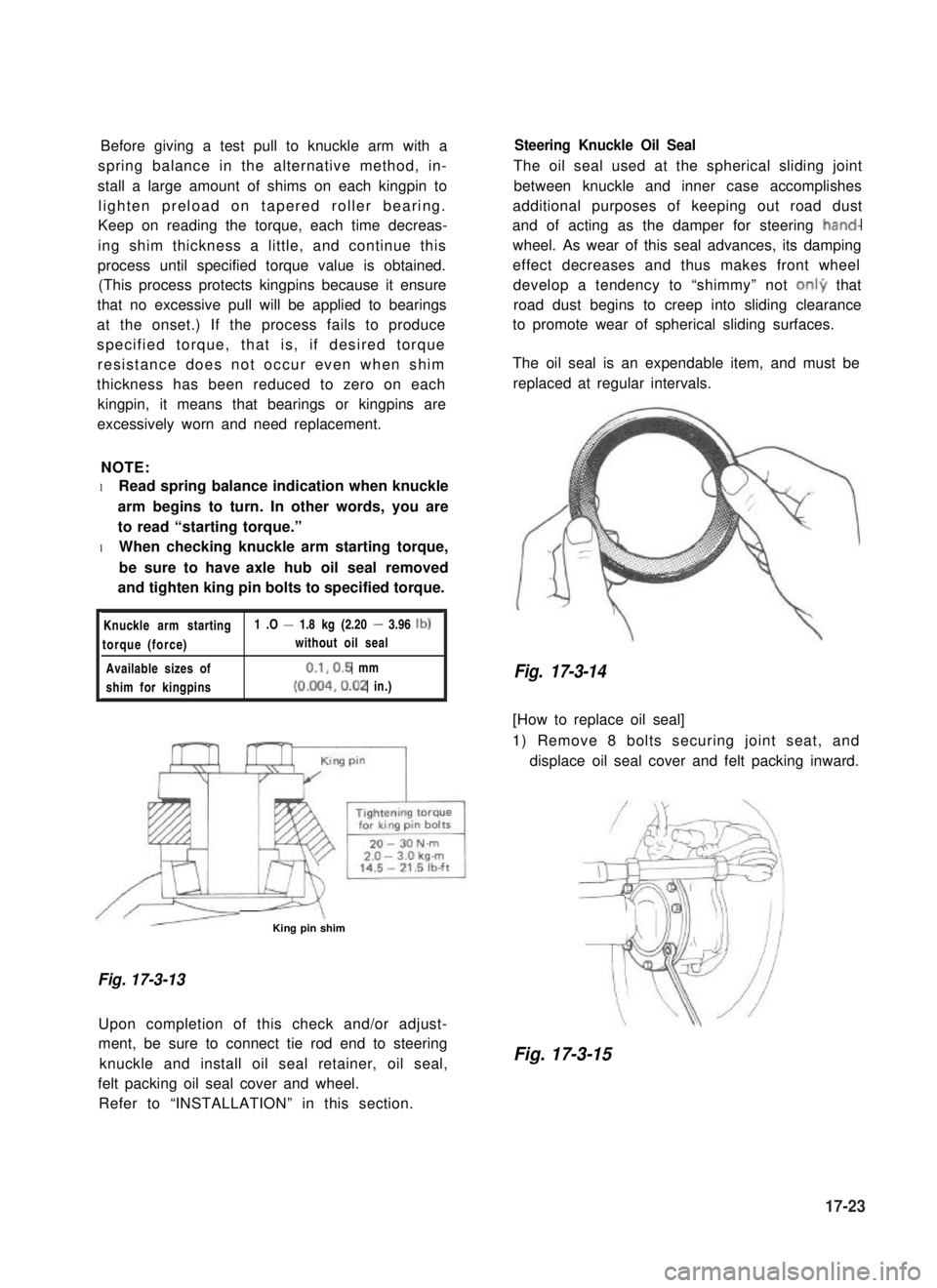
Before giving a test pull to knuckle arm with a
spring balance in the alternative method, in-
stall a large amount of shims on each kingpin to
lighten preload on tapered roller bearing.
Keep on reading the torque, each time decreas-
ing shim thickness a little, and continue this
process until specified torque value is obtained.
(This process protects kingpins because it ensure
that no excessive pull will be applied to bearings
at the onset.) If the process fails to produce
specified torque, that is, if desired torque
resistance does not occur even when shim
thickness has been reduced to zero on each
kingpin, it means that bearings or kingpins are
excessively worn and need replacement.
NOTE:
l Read spring balance indication when knuckle
arm begins to turn. In other words, you are
to read “starting torque.”
l When checking knuckle arm starting torque,
be sure to have axle hub oil seal removed
and tighten king pin bolts to specified torque.
Knuckle arm starting1 .O - 1.8 kg (2.20 - 3.96 lb)
torque (force)without oil seal
Available sizes of0.1,0.5 mm
shim for kingpins(0.004,0.02 in.)
/r--QzL- -\King pin shim
Fig. 17-3-13
Upon completion of this check and/or adjust-
ment, be sure to connect tie rod end to steering
knuckle and install oil seal retainer, oil seal,
felt packing oil seal cover and wheel.
Refer to “INSTALLATION” in this section.
Steering Knuckle Oil Seal
The oil seal used at the spherical sliding joint
between knuckle and inner case accomplishes
additional purposes of keeping out road dust
and of acting as the damper for steering hand-
wheel. As wear of this seal advances, its damping
effect decreases and thus makes front wheel
develop a tendency to “shimmy” not onI9 that
road dust begins to creep into sliding clearance
to promote wear of spherical sliding surfaces.
The oil seal is an expendable item, and must be
replaced at regular intervals.
Fig. 17-3-14
[How to replace oil seal]
1) Remove 8 bolts securing joint seat, and
displace oil seal cover and felt packing inward.
Fig. 17-3-15
17-23
Page 358 of 962
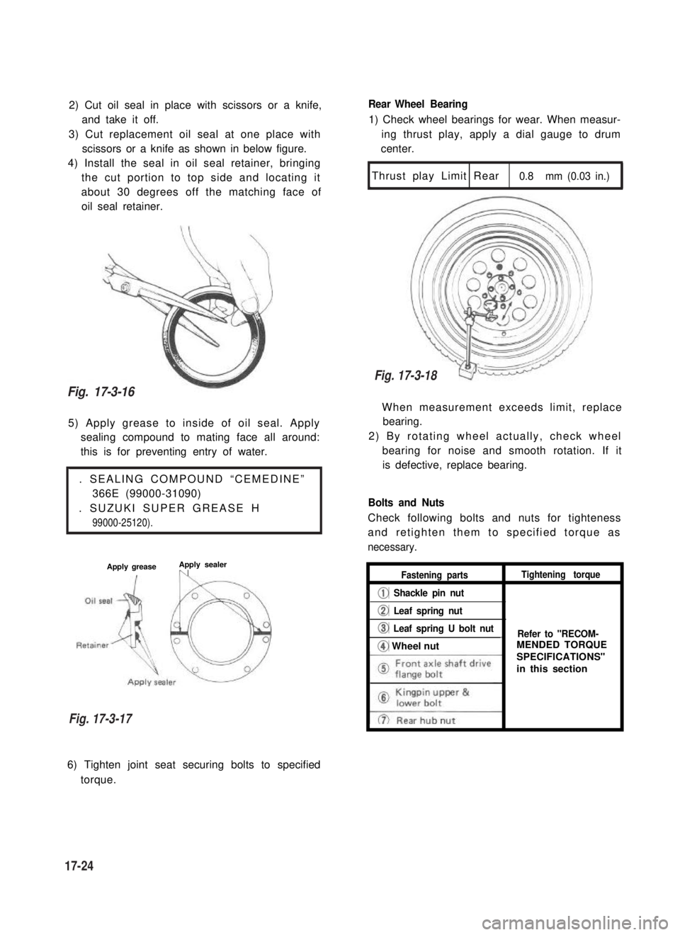
2) Cut oil seal in place with scissors or a knife,
and take it off.
3) Cut replacement oil seal at one place with
scissors or a knife as shown in below figure.
4) Install the seal in oil seal retainer, bringing
the cut portion to top side and locating it
about 30 degrees off the matching face of
oil seal retainer.
5) Apply grease to inside of oil seal. Apply
sealing compound to mating face all around:
this is for preventing entry of water.
. SEALING COMPOUND “CEMEDINE”
366E (99000-31090)
. SUZUKI SUPER GREASE H
99000-25120).
Apply greaseApply sealer,n
Rear Wheel Bearing
1) Check wheel bearings for wear. When measur-
ing thrust play, apply a dial gauge to drum
center.
Thrust play Limit Rear0.8 mm (0.03 in.)
1
When measurement exceeds limit, replace
bearing.
2) By rotating wheel actually, check wheel
bearing for noise and smooth rotation. If it
is defective, replace bearing.
Bolts and Nuts
Check following bolts and nuts for tighteness
and retighten them to specified torque as
necessary.
Fastening partsTightening torque
@ Shackle pin nut
@ Leaf spring nut
@ Leaf spring U bolt nut_Refer to "RECOM-
@ Wheel nut
6) Tighten joint seat securing bolts to specified
torque.
Fig. 17-3-16
Fig. 17-3-17
17-24
Fig. 17-3-18
MENDED TORQUE
SPECIFICATIONS"
in this section
Page 360 of 962
17-4. RECOMMENDED TORQUE SPECIFICATIONS
Fastening parts
Front wheel bearing lock nut
Differential oildrainplug18-251.8-2.513.5-18.0
Differential oilfiller& levelplug35- 503.5-5.025.5-36.0
Rear hub nut50 -805.0-8.036.5-57.5
17-26
Page 362 of 962
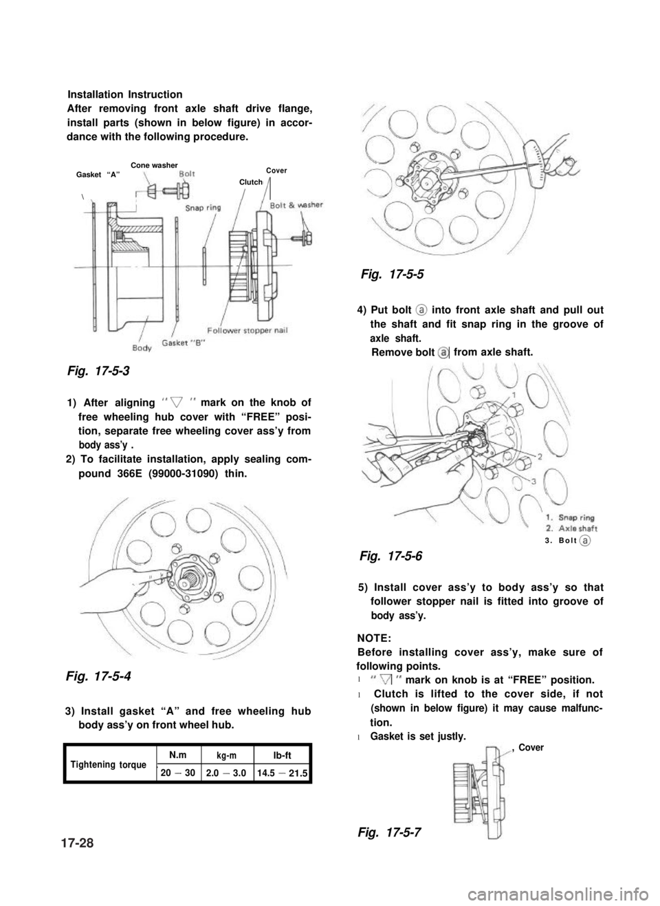
Installation Instruction
After removing front axle shaft drive flange,
install parts (shown in below figure) in accor-
dance with the following procedure.
Cone washerGasket “A”Cover
\
Clutch
II
Fig. 17-5-3
1) After aligning ” v” mark on the knob of
free wheeling hub cover with “FREE” posi-
tion, separate free wheeling cover ass’y from
body ass’y .
2) To facilitate installation, apply sealing com-
pound 366E (99000-31090) thin.
Fig. 17-5-4
3) Install gasket “A” and free wheeling hub
body ass’y on front wheel hub.
I
N.mkg-mlb-ftTighteningtorque.20-302.0-3.014.5-21.5
Fig. 17-5-5
4) Put bolt @ into front axle shaft and pull out
the shaft and fit snap ring in the groove of
axle shaft.
Remove bolt @from axle shaft.
3. Bolt (a)
Fig. 17-5-6
5) Install cover ass’y to body ass’y so that
follower stopper nail is fitted into groove of
body ass’y.
NOTE:
Before installing cover ass’y, make sure of
following points.
l “V” mark on knob is at “FREE” position.
l Clutch is lifted to the cover side, if not
(shown in below figure) it may cause malfunc-
tion.
l Gasket is set justly.
, Cover
Fig. 17-5-717-28
@