Page 98 of 962
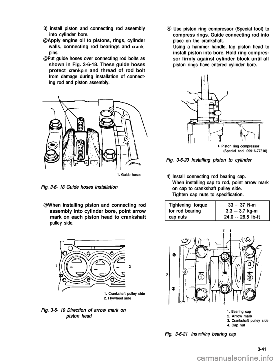
3) install piston and connecting rod assembly
into cylinder bore.
@Apply engine oil to pistons, rings, cylinder
walls, connecting rod bearings and crank-
pins.
@Put guide hoses over connecting rod bolts as
shown in Fig. 3-6-18. These guide hoses
protect crankpin and thread of rod bolt
from damage during installation of connect-
ing rod and piston assembly.
1. Guide hoses
Fig. 3-6- 18 Guide hoses installation
@When installing piston and connecting rod
assembly into cylinder bore, point arrow
mark on each piston head to crankshaft
pulley side.
1. Crankshaft pulley side
2. Flywheel side
Fig. 3-6- 19 Direction of arrow mark on
piston head
@ Use piston ring compressor (Special tool) to
compress rings. Guide connecting rod into
place on the crankshaft.
Using a hammer handle, tap piston head to
install piston into bore. Hold ring compres-
sor firmly against cylinder block until all
piston rings have entered cylinder bore.
1. Piston ring compressor
(Special tool 09916-77310)
Fig. 3-6-20 Installing piston to cylinder
4) Install connecting rod bearing cap.
When installing cap to rod, point arrow mark
on cap to crankshaft pulley side.
Tighten cap nuts to specification.
Tightening torque33-37 N-m
for rod bearing3.3-3.7 kg-m
cap nuts24.0-26.5 lb-ft
1. Bearing cap
2. Arrow mark3. Crankshaft pulley side
4. Cap nut
Fig. 3-6-21Ins tailing bearing cap
3-41
Page 99 of 962
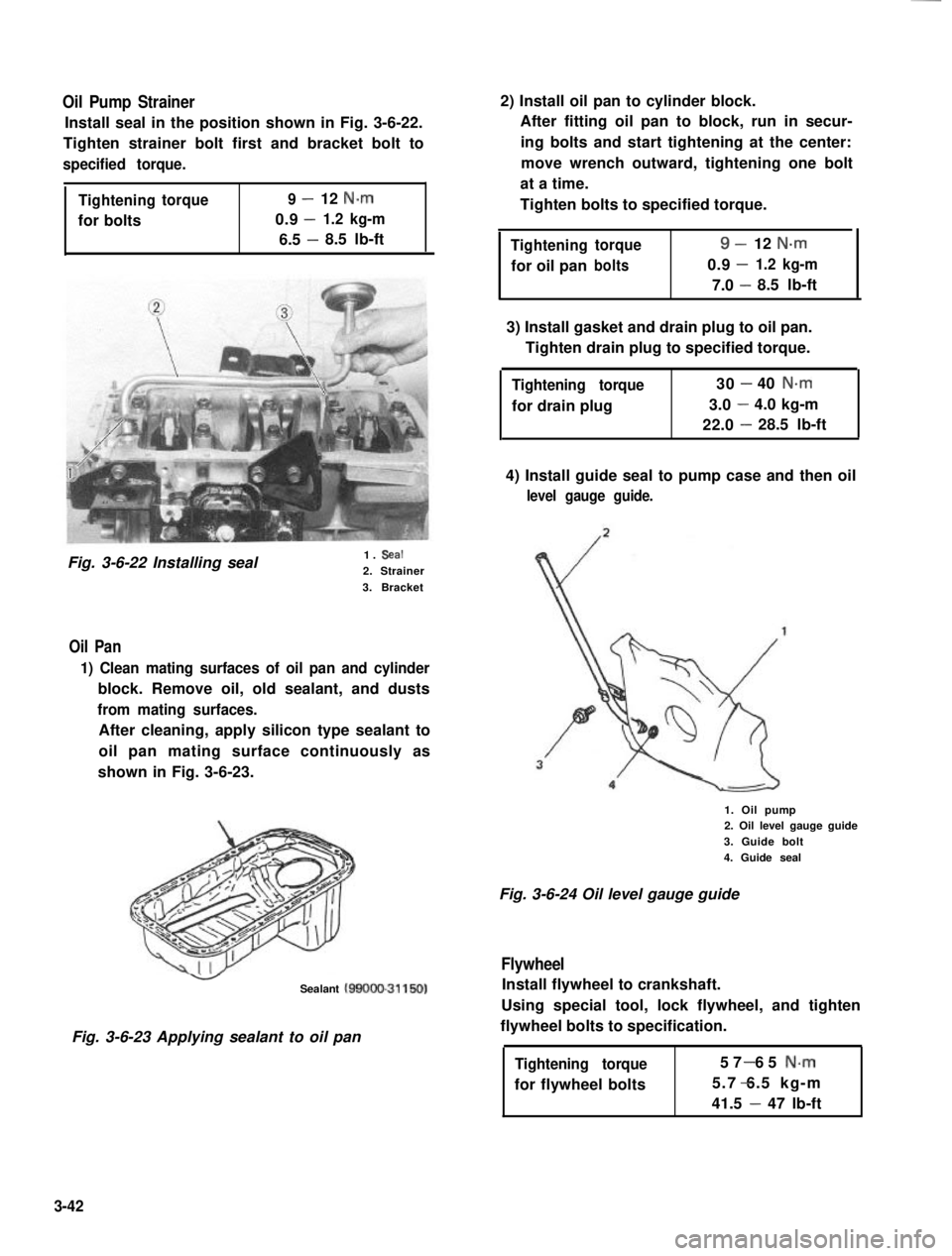
Oil Pump Strainer
Install seal in the position shown in Fig. 3-6-22.
Tighten strainer bolt first and bracket bolt to
specified torque.
Tighteningtorque9-12 N.m
0.9-for bolts1.2 kg-m
6.5 -8.5 lb-ft
Fig. 3-6-22 Installing seal1. Seal
2. Strainer
3. Bracket
Oil Pan
1) Clean mating surfaces of oil pan and cylinder
block. Remove oil, old sealant, and dusts
from mating surfaces.
After cleaning, apply silicon type sealant to
oil pan mating surface continuously as
shown in Fig. 3-6-23.
Sealant MOOO-31150)
Fig. 3-6-23 Applying sealant to oil pan
2) Install oil pan to cylinder block.
After fitting oil pan to block, run in secur-
ing bolts and start tightening at the center:
move wrench outward, tightening one bolt
at a time.
Tighten bolts to specified torque.
Tighteningtorque9-12 N-m
-for oil panbolts0.91.2 kg-m
7.0 -8.5 lb-ft
3) Install gasket and drain plug to oil pan.
Tighten drain plug to specified torque.
Tightening torque
for drain plug
30-40 N.m
3.0-4.0 kg-m
22.0-28.5 lb-ft
4) Install guide seal to pump case and then oil
level gauge guide.
1. Oil pump2. Oil level gauge guide
3. Guide bolt
4. Guide seal
Fig. 3-6-24 Oil level gauge guide
Flywheel
Install flywheel to crankshaft.
Using special tool, lock flywheel, and tighten
flywheel bolts to specification.
Tightening torque
for flywheel bolts
57 65 N-m-
5.7 6.5 kg-m-
41.5 - 47 lb-ft
3-42
Page 102 of 962
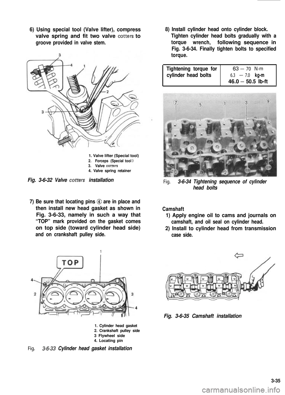
6) Using special tool (Valve lifter), compress
valve spring and fit two valve totters to
groove provided in valve stem.
1. Valve lifter (Special tool)
2.Forceps (Specialtool13.Valve totters4. Valve spring retainer
Fig. 3-6-32 Valve totters installation
7) Be sure that locating pins @ are in place and
then install new head gasket as shown in
Fig. 3-6-33, namely in such a way that
“TOP” mark provided on the gasket comes
on top side (toward cylinder head side)
and on crankshaft pulley side.
1
4
4
1. Cylinder head gasket2. Crankshaft pulley side
3 Flywheel side4. Locating pin
Fig. 3-6-33 Cylinder head gasket installation
8) Install cylinder head onto cylinder block.
Tighten cylinder head bolts gradually with a
torquewrench,following sequence in
Fig. 3-6-34. Finally tighten bolts to specified
torque.
Tightening torque for63-70 N-m
cylinder head bolts6.3-7.0 kg-m
46.0 -50.5 lb-ft
Fig. 3-6-34 Tightening sequence of cylinder
head bolts
Camshaft
1) Apply engine oil to cams and journals on
camshaft, and oil seal on cylinder head.
2) Install to cylinder head from transmission
case side.
Fig. 3-6-35 Camshaft installation
3-35
Page 105 of 962
Timing Belt Inside Cover, Belt Pulleys,
Tensioner, Timing Belt and Outside Cover
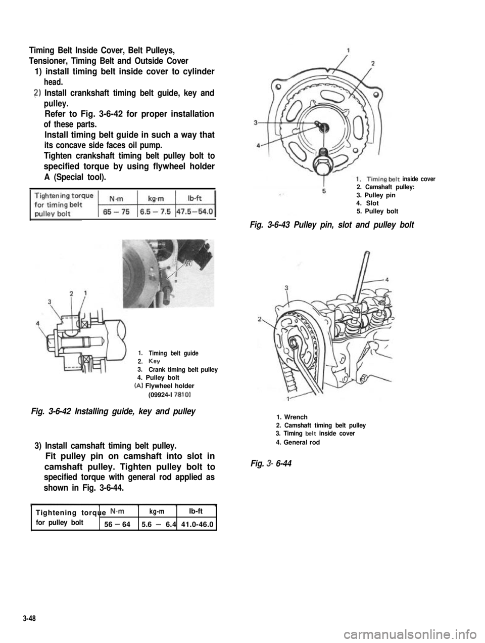
1) install timing belt inside cover to cylinder
head.
2) Install crankshaft timing belt guide, key and
pulley.
Refer to Fig. 3-6-42 for proper installation
of these parts.
Install timing belt guide in such a way that
its concave side faces oil pump.
Tighten crankshaft timing belt pulley bolt to
specified torque by using flywheel holder
A (Special tool).
1.
2.3.
Timing belt guide
KeyCrank timing belt pulley4. Pulley bolt
(A) Flywheel holder
(09924-I 7810)
Fig. 3-6-42 Installing guide, key and pulley
3) Install camshaft timing belt pulley.
Fit pulley pin on camshaft into slot in
camshaft pulley. Tighten pulley bolt to
specified torque with general rod applied as
shown in Fig. 3-6-44.
inside cover2. Camshaft pulley:
3. Pulley pin4. Slot5. Pulley bolt
Fig. 3-6-43 Pulley pin, slot and pulley bolt
1. Wrench
2. Camshaft timing belt pulley3. Timing belt inside cover
4. General rod
Fig. 3- 6-44
Tightening torque N-mkg-mlb-ft
for pulley bolt56 - 645.6 - 6.4 41.0-46.0
3-48
Page 107 of 962
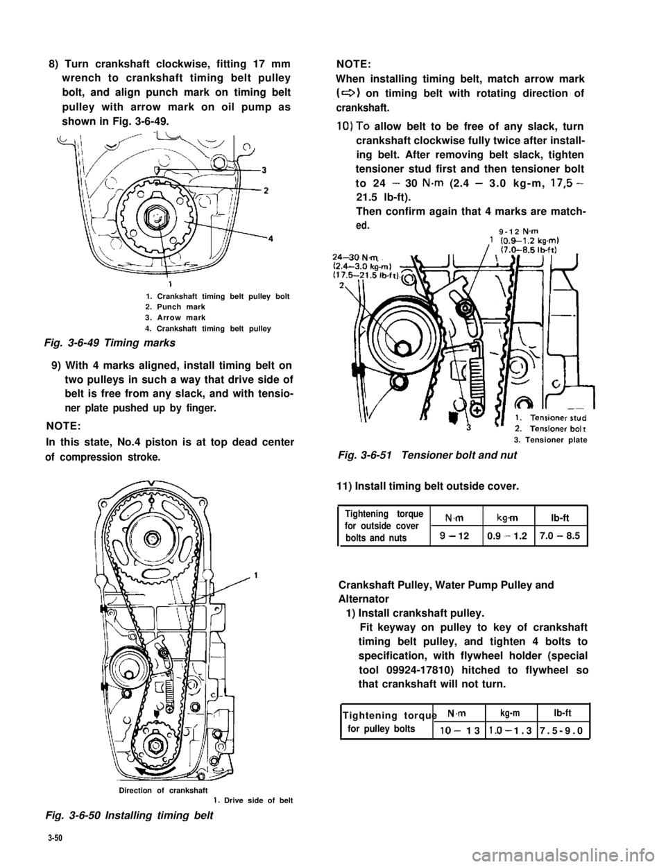
8) Turn crankshaft clockwise, fitting 17 mm
wrench to crankshaft timing belt pulley
bolt, and align punch mark on timing belt
pulley with arrow mark on oil pump as
shown in Fig. 3-6-49.
1. Crankshaft timing belt pulley bolt2. Punch mark3. Arrow mark
4. Crankshaft timing belt pulley
Fig. 3-6-49 Timing marks
9) With 4 marks aligned, install timing belt on
two pulleys in such a way that drive side of
belt is free from any slack, and with tensio-
ner plate pushed up by finger.
NOTE:
In this state, No.4 piston is at top dead center
of compression stroke.
NOTE:
When installing timing belt, match arrow mark
(+I on timing belt with rotating direction of
crankshaft.
10)To allow belt to be free of any slack, turn
crankshaft clockwise fully twice after install-
ing belt. After removing belt slack, tighten
tensioner stud first and then tensioner bolt
to 24 - 30 N.m (2.4 - 3.0 kg-m, 17,5 -
21.5 lb-ft).
Then confirm again that 4 marks are match-
ed.9-12 N-m
3. Tensioner plate
Fig. 3-6-51Tensioner bolt and nut
11) Install timing belt outside cover.
Tightening torque
for outside coverN.mkmlb-ft
bolts and nuts9- 120.9 - 1.27.0 - 8.5
Crankshaft Pulley, Water Pump Pulley and
Alternator
1) Install crankshaft pulley.
Fit keyway on pulley to key of crankshaft
timing belt pulley, and tighten 4 bolts to
specification, with flywheel holder (special
tool 09924-17810) hitched to flywheel so
that crankshaft will not turn.
Tightening torque N.mkg-mlb-ft
for pulley boltslo- 13 1.3 7.5-9.0*
Direction of crankshaft1. Drive side of belt
Fig. 3-6-50 Installing timing belt
3-50
Page 111 of 962
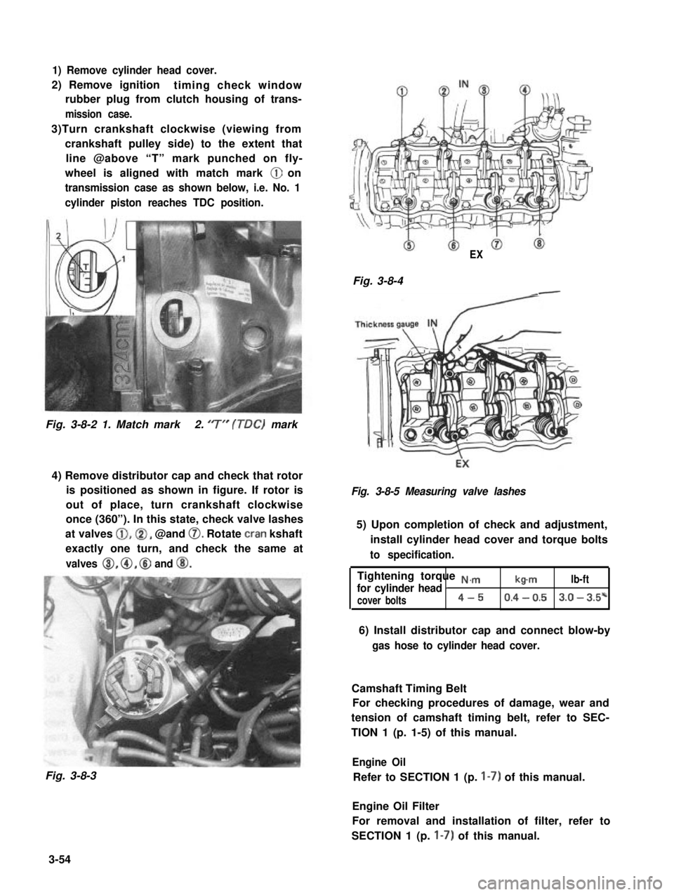
1) Remove cylinder head cover.
2) Remove ignitiontiming check window
rubber plug from clutch housing of trans-
mission case.
3)Turn crankshaft clockwise (viewing from
crankshaft pulley side) to the extent that
line @above “T” mark punched on fly-
wheel is aligned with match mark @ on
transmission case as shown below, i.e. No. 1
cylinder piston reaches TDC position.
Fig. 3-8-2 1. Match mark2. ‘7” (TDC) mark
4) Remove distributor cap and check that rotor
is positioned as shown in figure. If rotor is
out of place, turn crankshaft clockwise
once (360”). In this state, check valve lashes
at valves @,@I, @and 0. Rotate cran kshaft
exactly one turn, and check the same at
valves 8, @, @ and @I.
Fig. 3-8-3
EX
Fig. 3-8-4-
Fig. 3-8-5 Measuring valve lashes
5) Upon completion of check and adjustment,
install cylinder head cover and torque bolts
to specification.
Tightening torque N.,.,.,
for cylinder head Ib-mlb-ft
cover bolts4-50.4 - 0.53.0 - 3.5*
6) Install distributor cap and connect blow-by
gas hose to cylinder head cover.
Camshaft Timing Belt
For checking procedures of damage, wear and
tension of camshaft timing belt, refer to SEC-
TION 1 (p. 1-5) of this manual.
Engine Oil
Refer to SECTION 1 (p. I-7) of this manual.
Engine Oil Filter
For removal and installation of filter, refer to
SECTION 1 (p. I-7) of this manual.
3-54
Page 115 of 962
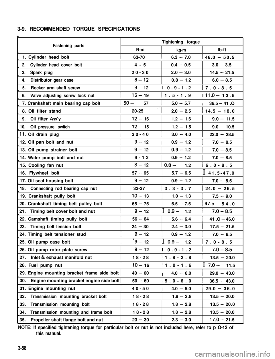
3-9. RECOMMENDED TORQUE SPECIFICATIONS
Fastening partsN-m
Tightening torque
kg-mlb-ft
1. Cylinder head bolt1 63-7016.3 - 7.01 46.0 - 50.5
2.Cylinder head cover bolt4-50.4-0.53.0-3.5
3.Spark plug20-302.0-3.014.5-21.5
4.Distributor gear case8-120.8-1.26.0-8.5
5.Rocker arm shaft screwI9- 12I 0.9-1.21 7.0-8.5
6.Valve adjusting screw lock nut
7. Crankshaft main bearing cap bolt
8. Oil filter stand
I15- 191 1.5-1.9I ll.O- 13.5
1 50- 5715.0 - 5.7136.5 - 41 .O
I20-25 -. 12.0 - 2.51 14.5 - 18.0
9.Oilfilter Ass’y12-161.2-1.69.0-11.5
10.Oilpressure switch12-151.2-1.59.0-10.5
11. Oil drain plugI30-40I3.0 - 4.0122.0 - 28.5
12. Oil pan bolt and nutI9- 12I0.9 - 1.2I7.0 - 8.5
13. Oil pump strainer bolt
14. Water pump bolt and nut
I9- 12I0.9 - 1.2I7.0 - 8.5
I9-12I0.9 - 1.2I7.0 - 8.5
15. Cooling fan nutI8- 121 0.8- 1.21 6.0-8.5
16. Flywheel boltI57 - 65I5.7 - 6.5I 41.5-47.0
17. Oil seal housing boltI9- 12I0.9 - 1.2I7.0 - 8.5
18.Connecting rod bearing cap nut1 33-37( 3.3-3.71 24.0 - 26.5
19. Crankshaft pully boltIlo- 13I1.0 - 1.3I7.5 - 9.0
20. Crankshaft timing belt pulley bolt
21.Timing belt cover bolt and nut
I65 - 75I6.5 - 7.51 47.5- 54.0
I9- 12I 0.9- 1.21 7-O-8.5
22. Camshaft timing pully boltI56 - 6415.6 - 6.4141 .O - 46.0III
23.Timingbelttensionbolt24-302.4-3.0117.5-21.5
24. Timing belt tensioner studI9- 12I0.9 - 1.2I7.0 - 8.5
25. Oil pump case boltI‘9- 12I 0.9- 1.21 7.0-8.5
26. Oil pump rotor plate screwI9- 12I 0.9-1.21 7-O-8.5
27.Inlet & exhaust manifold nutI18-281 1.8-2.8I13.5 - 20.0
28. Fuel pump nutIlo- 161 1.0-1.6I 7.0- 11.5
29. Engine mounting bracket frame side bolt 140 - 60I ~~~4.0 - 6.0129.0 - 43.0
30.Engine mounting bracket engine side bolt I50 - 601 5.0-6.0136.5 - 43.0
31. Engine mounting nutI40-50I4.0 - 5.01 29.0 - 36.0I1I
32.Transmissionmountingbracketbolt18-281.8-2.8113.5-20.0
33.Transmission mounting bolt18-281.8-2.813.5 -20.0
34.Transmission mounting and framebolt18-281.8-2.813.5 -20.0
35.Propeller shaft flange bolt and nut23 - 302.3-3.017.0-21.5
NOTE: If specified tightening torque for particular bolt or nut is not included here, refer to p O-12 of
this manual.
3-58
Page 255 of 962
2) For right-hand side steering vehicle.
Air cleaner outlethoseAircleaner
Radiator outlet
Air cleaner outlet hose
Clutch cable
Cla&p
Viewed from arrow “A”
40 - 60 N.m4.0 - 6.0 kg-m
I
Viewedfrom arrow“6”
Radiator
Fig. 11-23
Warmair hoseViewed from arrow “C”
11-6. RECOMMENDED TORQUE SPECIFICATION
Be sure to torque each nut or bolt, if loosened, to specification given below.
If specified tightening torque for particular bolt or nut is not included here, refer to p. O-12 of this manual.
Fastening PartsTightening torque
, N.mkg-mlb-ft
1.Flywheelbolts57-655.7-6.541.5-47.0
2.Clutchcover bolts18-281.B-2.613.5-20.0
3.Clutchrelease armboltandnutlo- 161.O-1.67.5-11.5.
11-10