Page 386 of 962

SECTION 19
BRAKES
CONTENTS
19-1. GENERAL DESCRIPTION................................. 19-2
19-2. FRONT DISC BRAKE..................................... 19-14
19-3. REAR DRUM BRAKE..................................... 19-20
19-4. MASTER CYLINDER..................................... 19-27
19-5. BRAKE BOOSTER....................................... 19-30
19-6. PARKING BRAKE........................................ 19-38
19-7. BRAKE PIPES AND HOSES . . . . . . . . . . . . . . . . . . . . . . . . . . . . . . . 19-39
19-8. MAINTENANCE SERVICE . . . . . . . . . . . . . . . . . . . . . . . . . . . . . . . . 19-42
19-9. TORQUE SPECIFICATION.. . . . . . . . . . . . . . . . . . . . . . . . . . . . . . . 19-49
NOTE:
All brake fasteners are important attaching parts in that they could affect the performance
of vital parts and systems, and/or could result in major repair expense. They must be
replaced with one of same part number or with an equivalent part if replacement becomes
necessary. Do not use a replacement part of lesser quality or substitute design. Torque
values must be used as specified during reassembly to assure proper retention of all parts.
There is to be no welding as it may result in extensive damage and weakening of the
metal.
WARNING:
When servicing wheel brake parts, do not create dust by grinding, sanding brake linings,
or by cleaning wheel brake parts with a dry brush or with compressed air. Many wheel
brake parts contain asbestos fibers which can become airborned if dust is created dur-
ing servicing. Breathing dust containing asbestos fibers may cause serious bodily harm.
A water dampened cloth or water based solution should be used to remove any dust
on brake parts. Equipment is commercially available to perform this washing function.
These wet methods will prevent asbestos fibers from becoming airborne.
19-1
Page 389 of 962
![SUZUKI GRAND VITARA 1987 Service Repair Manual MASTER CYLINDER ASSEMBLY
[GENERAL DESCRIPTION]
The master cylinder has two pistons and three piston cups. Its hydraulic pressure is produced in the
primary (“a” in the below figure) and secondary SUZUKI GRAND VITARA 1987 Service Repair Manual MASTER CYLINDER ASSEMBLY
[GENERAL DESCRIPTION]
The master cylinder has two pistons and three piston cups. Its hydraulic pressure is produced in the
primary (“a” in the below figure) and secondary](/manual-img/20/57437/w960_57437-388.png)
MASTER CYLINDER ASSEMBLY
[GENERAL DESCRIPTION]
The master cylinder has two pistons and three piston cups. Its hydraulic pressure is produced in the
primary (“a” in the below figure) and secondary (“b”) chambers. The hydraulic pressure produced in the
primary chamber (“a”) acts on the front wheel brakes (right & left).
Also, the hydraulic pressure produced in the secondary chamber (“b”) acts on the rear wheel brakes
(right & left).
NOTE:
Replace all components included in repair kits to service this master cylinder. Lubricate rubber parts with
clean, fresh brake fluid to ease assembly. Do not use lubricated shop air on brake parts as damage to rubber
components may result. If any hydraulic component is removed or brake line disconnected, bleed the
brake system. The torque values specified are for dry, unlubricated fasteners.
1.Piston stopper circllp
2.Piston stopper
3.Piston stopper sealing
4.Primary piston
5.Piston cup
6.Secondary piston pressure cup
7.Piston cup
8Secondary piston
9.Return spring secondary seat
10.Secondary piston return spring
11.Secondary piston stopper bolt
12.Master cylinder body
A :Primary piston
BSecondary piston
Fig. 19-3
[Master cylinder OPERATION]
Normal operation
Depressing the brake pedal forces the primary piston“A” to move to the left in the below figure and
consequently the hydraulic pressure is produced in the chamber “a”.
By means of this pressure and the return spring force, the secondary piston “B” is also pushed to the left
and thus the hydraulic pressure is produced in the chamber “b”.
Fig. 19-3-1
19-4
Page 393 of 962
![SUZUKI GRAND VITARA 1987 Service Repair Manual DRUM BRAKE ASSEMBLY (Rear Wheel Brake)
[GENERAL DESCRIPTION]
The drum brake assembly has a self shoe clearance adjusting system so that drum-to-shoe clearance is
maintained appropriate at all times. F SUZUKI GRAND VITARA 1987 Service Repair Manual DRUM BRAKE ASSEMBLY (Rear Wheel Brake)
[GENERAL DESCRIPTION]
The drum brake assembly has a self shoe clearance adjusting system so that drum-to-shoe clearance is
maintained appropriate at all times. F](/manual-img/20/57437/w960_57437-392.png)
DRUM BRAKE ASSEMBLY (Rear Wheel Brake)
[GENERAL DESCRIPTION]
The drum brake assembly has a self shoe clearance adjusting system so that drum-to-shoe clearance is
maintained appropriate at all times. For details, refer to OPERATION in the next page.
NOTE:
Replace all components included in repair kits used to service this drum brake. Lubricate parts as specified.
WARNING:
When servicing wheel brake parts, do not create dust by grinding or sanding brake linings or by clean-
ing wheel brake parts with a dry brush or with compressed air. (A water dampened cloth should be
used.) Many wheel brake parts contain asbestos fibers which can become airborne if dust is created
during servicing Breathing dust containing asbestos fibers may cause serious bodily harm. If any
hydraulic component is removed or brake line disconnected, bleed the brake system. The torque
values specified are for dry, unlubricated fasteners.
1. Brake back plate
2. Brake shoe
3. Shoe return spring (A)4. Brake strut rod
5. Shoe return spring (B)
6. Rod spring7. Shoe hold down spring
8. Shoe hold down pin
9. Wheel cylinder10. Stopper plateiI7
Fig. 19-8
19-8
Page 404 of 962

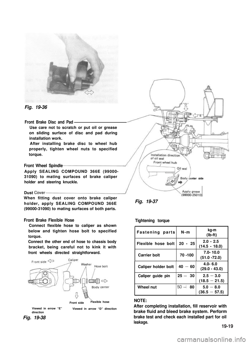
Fig. 19-36
Front Brake Disc and Pad
Use care not to scratch or put oil or grease
on sliding surface of disc and pad during
installation work.
After installing brake disc to wheel hub
properly, tighten wheel nuts to specified
torque.
Front Wheel Spindle
Apply SEALING COMPOUND 366E (99000-
31090) to mating surfaces of brake caliper
holder and steering knuckle.nter side
Dust Cover/
When fitting dust cover onto brake caliper
holder, apply SEALING COMPOUND 366E
(99000-31090) to mating surfaces of both parts.
Front Brake Flexible Hose
Connect flexible hose to caliper as shown
below and tighten hose bolt to specified
torque.
Connect the other end of hose to chassis body
bracket, being careful not to kink it with
front wheels directed straightforward.
\Front sideFlexible hose
Viewed in errow “E”Viewed in arrow “D” directiondirection
Fig. 19-38
V(gg!&
Fig. 19-37
Tightening torque
Fastening parts N-mkg-m
(lb-ft)
Flexible hose bolt 20 - 252.0 - 2.5
(14.5 -18.0)
Carrier bolt 70 -100
Caliper holder bolt 40 -60
Caliper guide pin25 -302.5-3.0
(18.5-21.5)
Wheel nut50-805.0-8.0
(36.5-57.5)
NOTE:
After completing installation, fill reservoir with
brake fluid and bleed brake system. Perform
brake test and check each installed part for oil
leakage.
(51.0 -72.0)
7.0- 10.0
4.0- 6.0
(29.0 - 43.0)
19-19
Page 409 of 962
6) Remove brake drum and check fan-shaped
ratchet position.
If it has shifted off its previous position in step
2) when it was pushed down, it proves proper
operation of shoe adjusting system.
PRECAUTIONS ON INSTALLATION
Wheel Cylinder
1) Tighten wheel cylinder to brake back plate to
specified torque.
2)Tighten flare nut of brake pipe to specified
torque.
3) Install breather plug cap.
8-12N.m14-18N.m-(0.8 - 1.2 kg-m)(I .41.8 kg-m)4,(6.0 - 8.5 lb-ft)(10.5-13.0 lb-ft)
1. Brake back plate3. Brake pipe
2. Brake pipe flare nut4. Wheel cylinder bolts
Fig. 19-50
Brake Shoes
1) Assemble parts as shown in the reverse order
of removal.
If not, replace strut assembly.
Fig. 19-49-4
NOTE:
For brake drum installation, refer to steps 1)
through 8) of brake drum installation in this
section (p. 19-25).
Fig. 19-50-1
NOTE:
When installing shoes, use care not to cause
damage to wheel cylinder boots.
19-24
Page 411 of 962
4) Before installing brake drum, to maximize
brake shoe-todrum clearance, put screw
driver between rod and ratchet and push
down ratchet as shown in figure.
\
2. Ratchet
3. Driver
Below figure shows ratchet positionwhere brake shoe-to-drum clearanceis maximum.
Fig. 19-54
5) Install brake drum after making sure that
inside of brake drum and brake shoes are free
from dirt and oil.
6) Torque wheel nuts and brake drum nuts to
specification.
NOTE:
If brake backing plate was removed from wheel
cylinder or brake pipe was disconnected from
wheel cylinder. Bleed air from brake system.
(For bleeding operation, refer to p. 19-46.)
7) Upon completion of all jobs, depress brake
pedal with about 30 kg (66 Ibs) load four or
five times so as to obtain proper drum-to-
shoe clearance.
8) Check to ensure that brake drum is free from
dragging and proper braking is obtained. Then
remove car from hoist and perform brake test
(foot brake and parking brake).
Fig. 19-55
19-26
Page 431 of 962

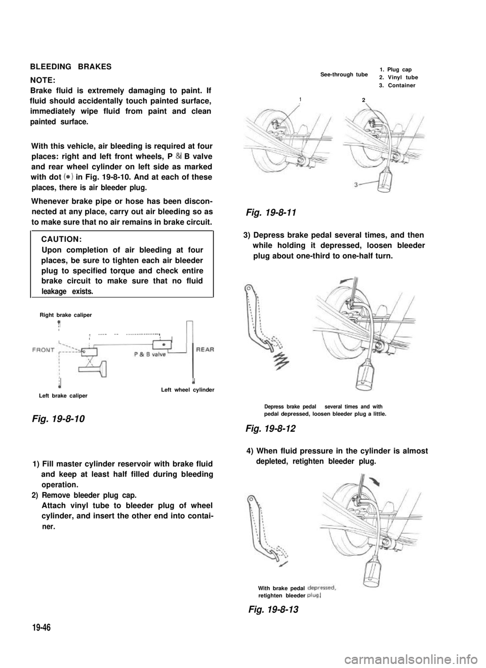
BLEEDING BRAKES
NOTE:
Brake fluid is extremely damaging to paint. If
fluid should accidentally touch painted surface,
immediately wipe fluid from paint and clean
painted surface.
With this vehicle, air bleeding is required at four
places: right and left front wheels, P & B valve
and rear wheel cylinder on left side as marked
with dot (0) in Fig. 19-8-10. And at each of these
places, there is air bleeder plug.
Whenever brake pipe or hose has been discon-
nected at any place, carry out air bleeding so as
to make sure that no air remains in brake circuit.
CAUTION:
Upon completion of air bleeding at four
places, be sure to tighten each air bleeder
plug to specified torque and check entire
brake circuit to make sure that no fluid
leakage exists.
Right brake caliper
?Ir ____ -- ---------------,IIAn
i
Left brake caliper
1Left wheel cylinder
Fig. 19-8-10
1) Fill master cylinder reservoir with brake fluid
and keep at least half filled during bleeding
operation.
2) Remove bleeder plug cap.
Attach vinyl tube to bleeder plug of wheel
cylinder, and insert the other end into contai-
ner.
See-through tube1. Plug cap2. Vinyl tube
2
3. Container
1
Fig. 19-8-11
3) Depress brake pedal several times, and then
while holding it depressed, loosen bleeder
plug about one-third to one-half turn.
Depress brake pedal several times and withpedal depressed, loosen bleeder plug a little.
Fig. 19-8-12
4) When fluid pressure in the cylinder is almost
depleted, retighten bleeder plug.
With brake pedalretighten bleederplug.
Fig. 19-8-13
19-46