Page 1323 of 2389
PREPARATION FOR DISASSEMBLY
1. (M/T)
REMOVE CLUTCH COVER AND DISC
2. (M/T)
REMOVE FLYWHEEL
3. (A/T)
REMOVE DRIVE PLATE
4 REMOVE REAR END PLATE
Remove the bolt and end plate.
5. INSTALL ENGINE TO ENGINE STAND FOR
DISASSEMBLY
6. REMOVE DISTRIBUTOR (See page IG±18)
7. REMOVE TIMING BELT AND PULLEYS
(See page EM±34)
8. REMOVE CYLINDER HEADS (See page EM±76)
9. REMOVE WATER PUMP (See page CO±9)
10. REMOVE OIL PAN AND OIL PUMP
(See page LU±17)
11. REMOVE OIL FILTER (See page LU±7)
12. REMOVE KNOCK SENSOR
Using SST, remove the knock sensor.
SST 09816±30010
13. REMOVE WATER BY±PASS PIPE
Remove the two bolts, two nuts and by±pass pipe.
14. REMOVE NO.2 IDLER PULLEY BRACKET
Remove the three bolts and mounting bracket.
± ENGINE MECHANICALCylinder Block (2VZ±FE)EM±146
Page 1324 of 2389
2. CHECK CONNECTING ROD THRUST CLEARANCE
Using a dial indicator, measure the thrust clearance while
moving the connecting rod back and forth.
Standard thrust clearance: 0.150 ± 0.330 mm
(0.0059 ± 0.0130 in.)
Maximum thrust clearance: 0.38 mm (0.0150 in.)
If the thrust clearance is greater than maximum, replace the
connecting rod assembly. If necessary, replace the crank-
shaft.
3. REMOVE CONNECTING ROD CAPS AND CHECK OIL
CLEARANCE
(a) Using a punch or numbering stamp, place the rnatchmarks
on the connecting rod and cap to ensure correct reas-
sembly.
(c) Using a plastic±faced hammer, lightly tap the connect-
ing rod bolts and lift off the connecting rod cap.
HINT: Keep the lower bearing inserted with the connect-
ing cap.
DISASSEMBLY OF CYLINDER BLOCK
(See page EM±139)
1. REMOVE REAR OIL SEAL RETAINER
Remove the six bolts and retainer.
(b) Using SST, remove the connecting rod cap nuts.
SST 09011±38121
± ENGINE MECHANICALCylinder Block (2VZ±FE)EM±147
Page 1325 of 2389
(i) Remove the connecting rod cap.
(j) Measure the Plastigage at widest point.
Standard oil clearance:
STD 0.028 ± 0.065 mm
(0.0011 ± 0.0026 in.)
U/S 0.25 0.027 ± 0.080 mm
(0.0011 ± 0.0031 in.)
Maximum oil clearance: 0.08 mm (0.0031 in.)
If the oil clearance is greater than maximum, replace
the bearings. If necessary, grind or replace the crank-
shaft. (e) Clean the crank pin and bearing.
(f) Check the crank pin and bearing for pitting and scratches.
If the crank pin or bearing is damaged, replace the bearing.
If necessary, grind or replace the crankshaft.
(h) Install the connecting rod cap.
(See step 6 on page EM±165)
Torque: 1st 250 kg±cm (18 ft±ib, 25 N±m)
2nd turns 90°
NOTICE: Do not turn the crankshaft
(d) Cover the connecting rod bolts with a short piece of
hose to protect the crankshaft from damage.
(g) Lay a strip of Plastigage across the crank pin.
± ENGINE MECHANICALCylinder Block (2VZ±FE)EM±148
Page 1326 of 2389

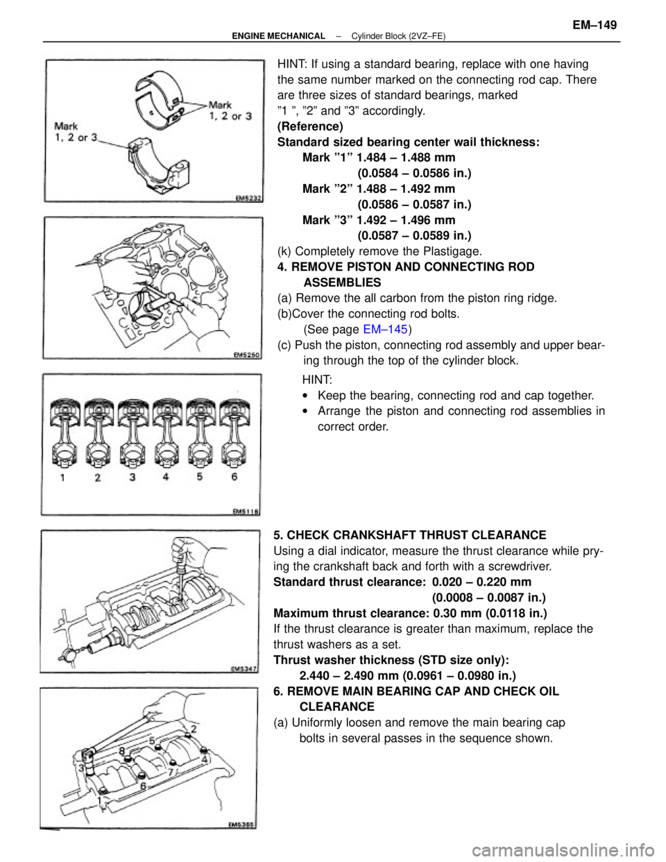
HINT: If using a standard bearing, replace with one having
the same number marked on the connecting rod cap. There
are three sizes of standard bearings, marked
º1 º, º2º and º3º accordingly.
(Reference)
Standard sized bearing center wail thickness:
Mark º1º 1.484 ± 1.488 mm
(0.0584 ± 0.0586 in.)
Mark º2º 1.488 ± 1.492 mm
(0.0586 ± 0.0587 in.)
Mark º3º 1.492 ± 1.496 mm
(0.0587 ± 0.0589 in.)
(k) Completely remove the Plastigage.
4. REMOVE PISTON AND CONNECTING ROD
ASSEMBLIES
(a) Remove the all carbon from the piston ring ridge.
(b)Cover the connecting rod bolts.
(See page EM±145)
(c) Push the piston, connecting rod assembly and upper bear-
ing through the top of the cylinder block.
5. CHECK CRANKSHAFT THRUST CLEARANCE
Using a dial indicator, measure the thrust clearance while pry-
ing the crankshaft back and forth with a screwdriver.
Standard thrust clearance: 0.020 ± 0.220 mm
(0.0008 ± 0.0087 in.)
Maximum thrust clearance: 0.30 mm (0.0118 in.)
If the thrust clearance is greater than maximum, replace the
thrust washers as a set.
Thrust washer thickness (STD size only):
2.440 ± 2.490 mm (0.0961 ± 0.0980 in.)
6. REMOVE MAIN BEARING CAP AND CHECK OIL
CLEARANCE
(a) Uniformly loosen and remove the main bearing cap
bolts in several passes in the sequence shown.HINT:
wKeep the bearing, connecting rod and cap together.
wArrange the piston and connecting rod assemblies in
correct order.
± ENGINE MECHANICALCylinder Block (2VZ±FE)EM±149
Page 1327 of 2389

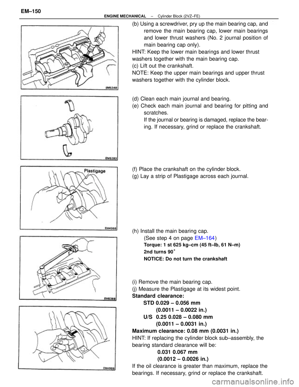
(i) Remove the main bearing cap.
(j) Measure the Plastigage at its widest point.
Standard clearance:
STD 0.029 ± 0.056 mm
(0.0011 ± 0.0022 in.)
U/S 0.25 0.028 ± 0.080 mm
(0.0011 ± 0.0031 in.)
Maximum clearance: 0.08 mm (0.0031 in.)
HINT: If replacing the cylinder block sub±assembly, the
bearing standard clearance will be:
0.031 0.067 mm
(0.0012 ± 0.0026 in.)
If the oil clearance is greater than maximum, replace the
bearings. If necessary, grind or replace the crankshaft. (b) Using a screwdriver, pry up the main bearing cap, and
remove the main bearing cap, lower main bearings
and lower thrust washers (No. 2 journal position of
main bearing cap only).
HINT: Keep the lower main bearings and lower thrust
washers together with the main bearing cap.
(c) Lift out the crankshaft.
NOTE: Keep the upper main bearings and upper thrust
washers together with the cylinder block.
(d) Clean each main journal and bearing.
(e) Check each main journal and bearing for pitting and
scratches.
If the journal or bearing is damaged, replace the bear-
ing. If necessary, grind or replace the crankshaft.
(h) Install the main bearing cap.
(See step 4 on page EM±164)
Torque: 1 st 625 kg±cm (45 ft±Ib, 61 N±m)
2nd turns 90°
NOTICE: Do not turn the crankshaft
(f) Place the crankshaft on the cylinder block.
(g) Lay a strip of Plastigage across each journal.
± ENGINE MECHANICALCylinder Block (2VZ±FE)EM±150
Page 1330 of 2389
DISASSEMBLY OF PISTON AND
CONNECTING ROD ASSEMBLIES
1. CHECK FIT BETWEEN PISTON AND PISTON PIN
Try to move the piston back and forth on the piston pin.
If any movement is felt, replace the piston and pin as a set.6. REMOVE CYLINDER RIDGE
If the wear is less than 0.2 mm (0.008 in.), use a ridge ream-
er to machine the piston ring ridge at the top of the cylinder.
2. REMOVE PISTON RINGS
(a) Using a piston ring expander, remove the two compres-
sion rings.
(b) Remove the two side rails and oil ring expander by
hand.
HINT: Arrange the rings in correct order only.
± ENGINE MECHANICALCylinder Block (2VZ±FE)EM±153
Page 1332 of 2389

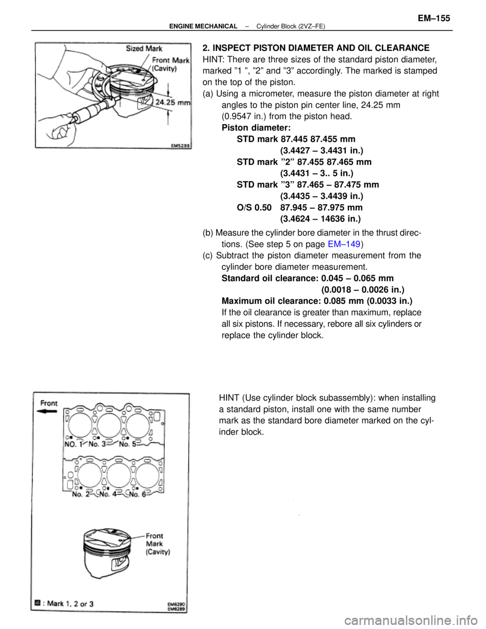
2. INSPECT PISTON DIAMETER AND OIL CLEARANCE
HINT: There are three sizes of the standard piston diameter,
marked º1 º, º2º and º3º accordingly. The marked is stamped
on the top of the piston.
(a) Using a micrometer, measure the piston diameter at right
angles to the piston pin center line, 24.25 mm
(0.9547 in.) from the piston head.
Piston diameter:
STD mark 87.445 87.455 mm
(3.4427 ± 3.4431 in.)
STD mark º2º 87.455 87.465 mm
(3.4431 ± 3.. 5 in.)
STD mark º3º 87.465 ± 87.475 mm
(3.4435 ± 3.4439 in.)
O/S 0.50 87.945 ± 87.975 mm
(3.4624 ± 14636 in.)
(b) Measure the cylinder bore diameter in the thrust direc-
tions. (See step 5 on page EM±149)
(c) Subtract the piston diameter measurement from the
cylinder bore diameter measurement.
Standard oil clearance: 0.045 ± 0.065 mm
(0.0018 ± 0.0026 in.)
Maximum oil clearance: 0.085 mm (0.0033 in.)
If the oil clearance is greater than maximum, replace
all six pistons. If necessary, rebore all six cylinders or
replace the cylinder block.
HINT (Use cylinder block subassembly): when installing
a standard piston, install one with the same number
mark as the standard bore diameter marked on the cyl-
inder block.
± ENGINE MECHANICALCylinder Block (2VZ±FE)EM±155
Page 1333 of 2389

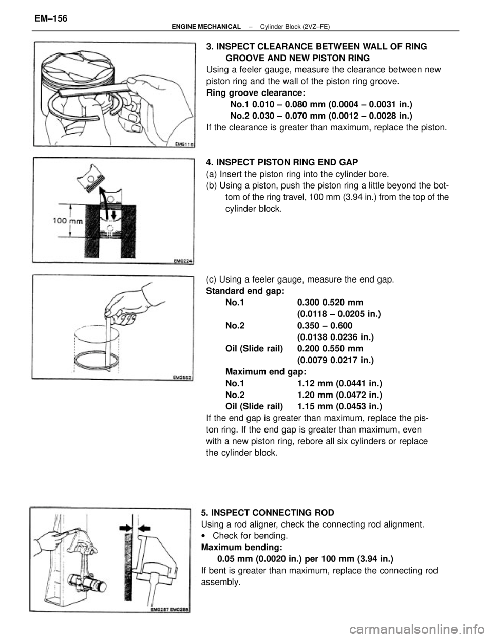
(c) Using a feeler gauge, measure the end gap.
Standard end gap:
No.1 0.300 0.520 mm
(0.0118 ± 0.0205 in.)
No.2 0.350 ± 0.600
(0.0138 0.0236 in.)
Oil (Slide rail) 0.200 0.550 mm
(0.0079 0.0217 in.)
Maximum end gap:
No.1 1.12 mm (0.0441 in.)
No.2 1.20 mm (0.0472 in.)
Oil (Slide rail) 1.15 mm (0.0453 in.)
If the end gap is greater than maximum, replace the pis-
ton ring. If the end gap is greater than maximum, even
with a new piston ring, rebore all six cylinders or replace
the cylinder block.3. INSPECT CLEARANCE BETWEEN WALL OF RING
GROOVE AND NEW PISTON RING
Using a feeler gauge, measure the clearance between new
piston ring and the wall of the piston ring groove.
Ring groove clearance:
No.1 0.010 ± 0.080 mm (0.0004 ± 0.0031 in.)
No.2 0.030 ± 0.070 mm (0.0012 ± 0.0028 in.)
If the clearance is greater than maximum, replace the piston.
5. INSPECT CONNECTING ROD
Using a rod aligner, check the connecting rod alignment.
wCheck for bending.
Maximum bending:
0.05 mm (0.0020 in.) per 100 mm (3.94 in.)
If bent is greater than maximum, replace the connecting rod
assembly.4. INSPECT PISTON RING END GAP
(a) Insert the piston ring into the cylinder bore.
(b) Using a piston, push the piston ring a little beyond the bot-
tom of the ring travel, 100 mm (3.94 in.) from the top of the
cylinder block.
± ENGINE MECHANICALCylinder Block (2VZ±FE)EM±156