Page 1306 of 2389

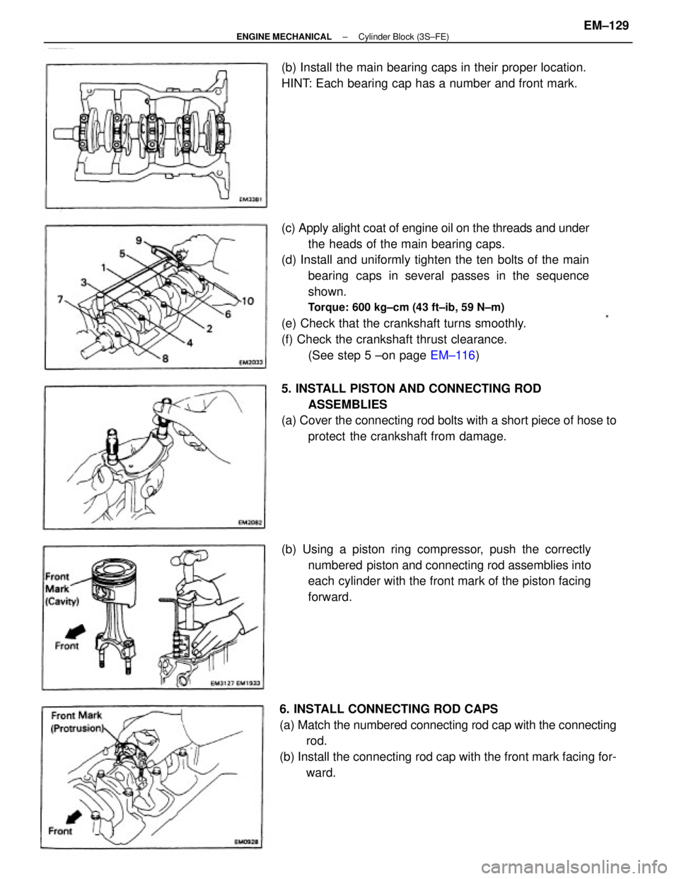
(c) Apply alight coat of engine oil on the threads and under
the heads of the main bearing caps.
(d) Install and uniformly tighten the ten bolts of the main
bearing caps in several passes in the sequence
shown.
Torque: 600 kg±cm (43 ft±ib, 59 N±m)
(e) Check that the crankshaft turns smoothly.
(f) Check the crankshaft thrust clearance.
(See step 5 ±on page EM±116)
6. INSTALL CONNECTING ROD CAPS
(a) Match the numbered connecting rod cap with the connecting
rod.
(b) Install the connecting rod cap with the front mark facing for-
ward. (b) Using a piston ring compressor, push the correctly
numbered piston and connecting rod assemblies into
each cylinder with the front mark of the piston facing
forward. 5. INSTALL PISTON AND CONNECTING ROD
ASSEMBLIES
(a) Cover the connecting rod bolts with a short piece of hose to
protect the crankshaft from damage. (b) Install the main bearing caps in their proper location.
HINT: Each bearing cap has a number and front mark.
± ENGINE MECHANICALCylinder Block (3S±FE)EM±129
Page 1307 of 2389
(c) Apply a light of engine oil on the threads and under the
nuts of the connecting rod cap.
(d) Install and alternately tighten the nuts of the connect-
ing rod cap in several passes.
Torque: 500 kg±cm (36 ft±Ib, 49 N±m)
(e) Check that the crankshaft turns smoothly.
M Check the connecting rod thrust clearance.
(See step 2 on page EM±114)
7. INSTALL REAR OIL SEAL RETAINER
Install a new gasket and the retainer with the six bolts.
Torque: 95 kg±cm (82 in.±Ib, 9.3 N±m)
± ENGINE MECHANICALCylinder Block (3S±FE)EM±130
Page 1308 of 2389
POST ASSEMBLY
1. INSTALL OIL PUMP AND OIL PAN
(See page LU±14)
2. INSTALL WATER PUMP (See page CO±7)
3. INSTALL CYLINDER HEAD (See page EM±67)
4. INSTALL PULLEYS AND TIMING BELT
(See page EM±29)
5. INSTALL ALTERNATOR (See page CH±14)
6. INSTALL DISTRIBUTOR (See page IG±16)
7. REMOVE ENGINE STAND
8. INSTALL REAR END PLATE
Torque: 95 kg±cm (82 ft±Ib, 9.3 N±m)
9. (M/T)
INSTALL FLYWHEEL
(a) Apply adhesive to two or three threads of the mount bolt
end.
Adhesive: Part No.08833±00070, THREE BOND 1324
or equivalent
10. (A/T)
INSTALL DRIVE PLATE
(See procedure step 9)
Torque: 850 kg±cm (61 ft±Ib, 83 N±m)
11. (M/T)
INSTALL CLUTCH DISC AND COVER (b) Install the flywheel on the crankshaft.
(c) Install and uniformly tighten the mount bolts in several
passes in the sequence shown.
Torque: 900 kg±cm (65 ft±Ib. 88 N±m)
± ENGINE MECHANICALCylinder Block (3S±FE)EM±131
Page 1311 of 2389

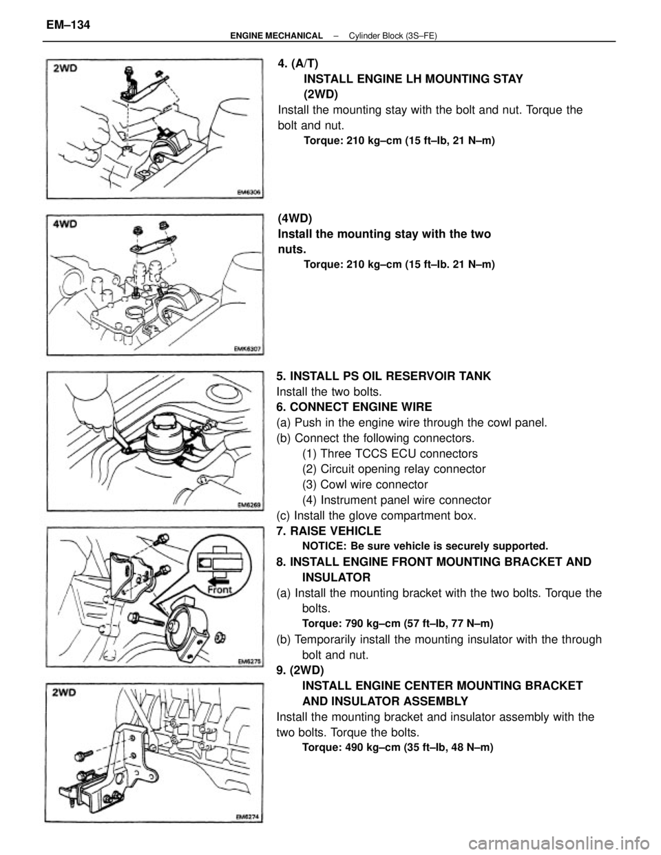
5. INSTALL PS OIL RESERVOIR TANK
Install the two bolts.
6. CONNECT ENGINE WIRE
(a) Push in the engine wire through the cowl panel.
(b) Connect the following connectors.
(1) Three TCCS ECU connectors
(2) Circuit opening relay connector
(3) Cowl wire connector
(4) Instrument panel wire connector
(c) Install the glove compartment box.
7. RAISE VEHICLE
NOTICE: Be sure vehicle is securely supported.
8. INSTALL ENGINE FRONT MOUNTING BRACKET AND
INSULATOR
(a) Install the mounting bracket with the two bolts. Torque the
bolts.
Torque: 790 kg±cm (57 ft±Ib, 77 N±m)
(b) Temporarily install the mounting insulator with the through
bolt and nut.
9. (2WD)
INSTALL ENGINE CENTER MOUNTING BRACKET
AND INSULATOR ASSEMBLY
Install the mounting bracket and insulator assembly with the
two bolts. Torque the bolts.
Torque: 490 kg±cm (35 ft±Ib, 48 N±m)
4. (A/T)
INSTALL ENGINE LH MOUNTING STAY
(2WD)
Install the mounting stay with the bolt and nut. Torque the
bolt and nut.
Torque: 210 kg±cm (15 ft±Ib, 21 N±m)
(4WD)
Install the mounting stay with the two
nuts.
Torque: 210 kg±cm (15 ft±Ib. 21 N±m)
± ENGINE MECHANICALCylinder Block (3S±FE)EM±134
Page 1315 of 2389

32. INSTALL BATTERY
33. FILL WITH ENGINE COOLANT (See page CO±5)
Capacity (w/ Heater):
M/T 6.4 liters (6.8 US qts, 5.6 Imp. qts)
A/T (2WD) 6.3 liters (6.7 US qts, 5.5 Imp. qts)
A/T (4WD) 6.8 liters (7.2 US qts, 6.0 Imp. qts)
34. FILL WITH ENGINE OIL (See page LU±8)
Capacity:
Drain and refill
w/ Oil filter change
3.9 liters (4.1 US qts, 3.4 Imp. qts)
w/o Oil filter change
3.7 liters (3.9 US qts, 3.3 Imp. qts)
Dry fill 4.3 liters (4.5 US qts, 3.8 Imp. qts)
35. START ENGINE AND CHECK FOR LEAKS
36. PERFORM ENGINE ADJUSTMENT
(a) Adjust the alternator drive belt.
(See page CH±3)
Drive belt tension:
w/ A/C New belt 175 + 5 lb
Used belt 130 + 10 lb
w/o A/C New belt 125 + 25 lb
Used belt 95 + 20 lb
(b) Adjust the PS drive belt.
Drive belt tension: New belt 125 + 25 lb
Used belt 80 + 20 lb
(c) Adjust the ignition timing.
(See steps 7 to 10 on pages IG±16 and 17)
Ignition timing:
10° BTDC @ idle
(w/ Terminals TE 1 and E1 connected)
(d) Adjust the valve. clearance. (See page EM±11)
Valve clearance:
Intake 0.19 ± 0.29 mm (0.007 ± 0.011 in.)
Exhaust 0.28 ± 0.38 mm (0.011 ± 0.015 in.)
37. INSTALL HOOD
38. PERFORM ROAD TEST
Check for abnormal noise, shock, slippage, correct shift
points and smooth operation.
39. RECHECK ENGINE COOLANT AND ENGINE OIL
LEVELS
± ENGINE MECHANICALCylinder Block (3S±FE)EM±138
Page 1317 of 2389

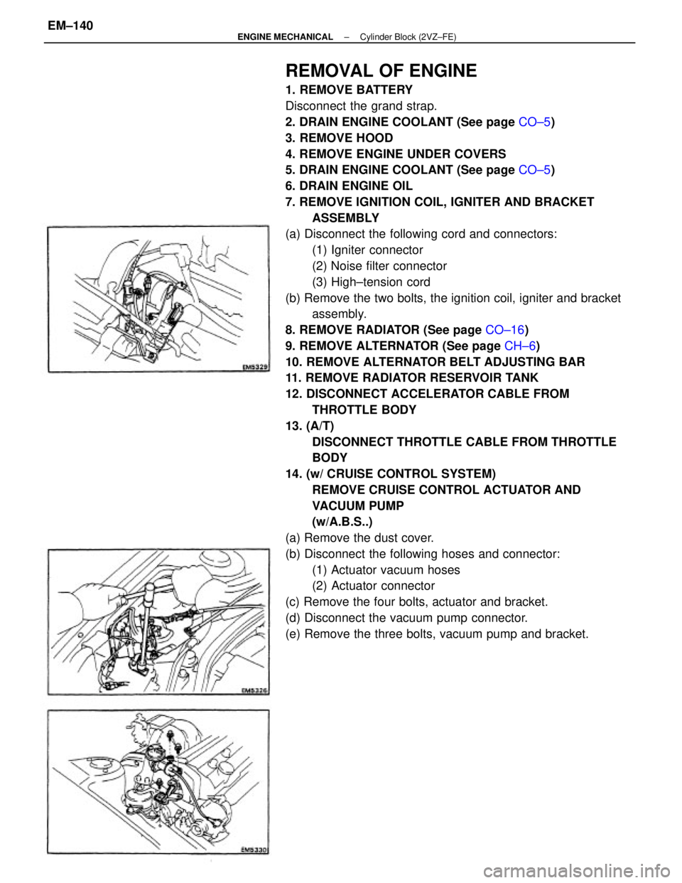
REMOVAL OF ENGINE
1. REMOVE BATTERY
Disconnect the grand strap.
2. DRAIN ENGINE COOLANT (See page CO±5)
3. REMOVE HOOD
4. REMOVE ENGINE UNDER COVERS
5. DRAIN ENGINE COOLANT (See page CO±5)
6. DRAIN ENGINE OIL
7. REMOVE IGNITION COIL, IGNITER AND BRACKET
ASSEMBLY
(a) Disconnect the following cord and connectors:
(1) Igniter connector
(2) Noise filter connector
(3) High±tension cord
(b) Remove the two bolts, the ignition coil, igniter and bracket
assembly.
8. REMOVE RADIATOR (See page CO±16)
9. REMOVE ALTERNATOR (See page CH±6)
10. REMOVE ALTERNATOR BELT ADJUSTING BAR
11. REMOVE RADIATOR RESERVOIR TANK
12. DISCONNECT ACCELERATOR CABLE FROM
THROTTLE BODY
13. (A/T)
DISCONNECT THROTTLE CABLE FROM THROTTLE
BODY
14. (w/ CRUISE CONTROL SYSTEM)
REMOVE CRUISE CONTROL ACTUATOR AND
VACUUM PUMP
(w/A.B.S..)
(a) Remove the dust cover.
(b) Disconnect the following hoses and connector:
(1) Actuator vacuum hoses
(2) Actuator connector
(c) Remove the four bolts, actuator and bracket.
(d) Disconnect the vacuum pump connector.
(e) Remove the three bolts, vacuum pump and bracket.
± ENGINE MECHANICALCylinder Block (2VZ±FE)EM±140
Page 1321 of 2389
35. REMOVE PS OIL RESERVOIR TANK WITHOUT
DISCONNECTING HOSES
Remove the two bolts and reservoir tank. Disconnect the
ground strap.
36. REMOVE ENGINE RH MOUNTING STAYS
(a) Remove the three bolts and No. 1 mounting stay.
(b) Remove the bolt, nut and No. 2 mounting stay.
38. REMOVE ENGINE AND TRANSAXLE ASSEMBLY
FROM VEHICLE
(a) Attach the engine hoist chain to the engine hangers.37. REMOVE ENGINE LH MOUNTING STAY
(M/T)
Remove the bolt, two nuts and mounting stay.
(A/T)
Remove the three nuts and mounting
stay.
± ENGINE MECHANICALCylinder Block (2VZ±FE)EM±144
Page 1322 of 2389
(f) Lift the engine out of the vehicle slowly and carefully.
NOTICE: Be careful not to hit the PS gear housing or
neutral start switch.
(g) Make sure the engine is clear of all wiring, hoses and
cables.
(h) Place the engine. and transaxle assembly onto the
stand. (d) Remove the through bolt, nut, four bolts and LH
mounting insulator.
(e) Remove the three bolts and LH mounting bracket. (b) (w/ A.B.S.)
Remove the clamp bolts of the PS oil cooler pipes.
(c) Remove the bolt, four nuts and RH mounting insulator.
39. (A/T)
REMOVE STARTER
40. SEPARATE ENGINE AND TRANSAXLE
± ENGINE MECHANICALCylinder Block (2VZ±FE)EM±145